RAMFAN ATEX User manual

San Diego |Luxembourg |Dubai | Ningbo | Singapore
FlowPath™Control
ATEX/IECEX
POWER EXTENSION CABLE
Instruction Manual

2
READ MANUAL BEFORE STARTING FOR THE FIRST TIME!
Thank you for purchasing the ATEX / IECEX POWER EXTENSION CABLE manufactured in the
USA by Euramco Group, Inc.
For more than 30 years Euramco Group has been on the cutting edge of industrial, re, and
marine ventilation products. Each of our blower/exhausters, smoke ejectors, PPV & LSV fans
and accessories represent the nest technologies available. Every product is constructed to
demanding and exact specications for quality, performance, and reliability.
When human life depends on having a fan that can deliver clean, safe air, you have only one
choice you can trust RAMFAN.
Explore our website and online catalog at www.euramco.com and discover how RAMFAN
can make a dierence in the eld.
All product information in the publication is based on the most current information available
at the time of printing. Euramco Group, Inc. reserves the right to make changes at anytime
without notice.

3
CONTENTS
General Description ................................................................................................................. 4
Part Number Denition ......................................................................................................... 5-6
Installation Instructions & Care ...................................................................................... 9-10
Cautions ................................................................................................................................. 11
Accessories ............................................................................................................................. 11
Warranty ................................................................................................................................. 12
How to Maintain Cables ........................................................................................................... 12
Declaration of Conformity .............................................................................................. 13-14

4
General Description
The Power Extension Cables described here are intended for use in Explosive Atmospheres
in accordance within the limitation of the ratings. It is the user's responsibility to determine
the suitability of the equipment for the intended purpose.
ATEX / IECEx Power Extension Cables are designed to temporarily extend the reach between
an AC power source and an electrical device, such as portable fans, area lighting, etc., for
use in hazardous locations.
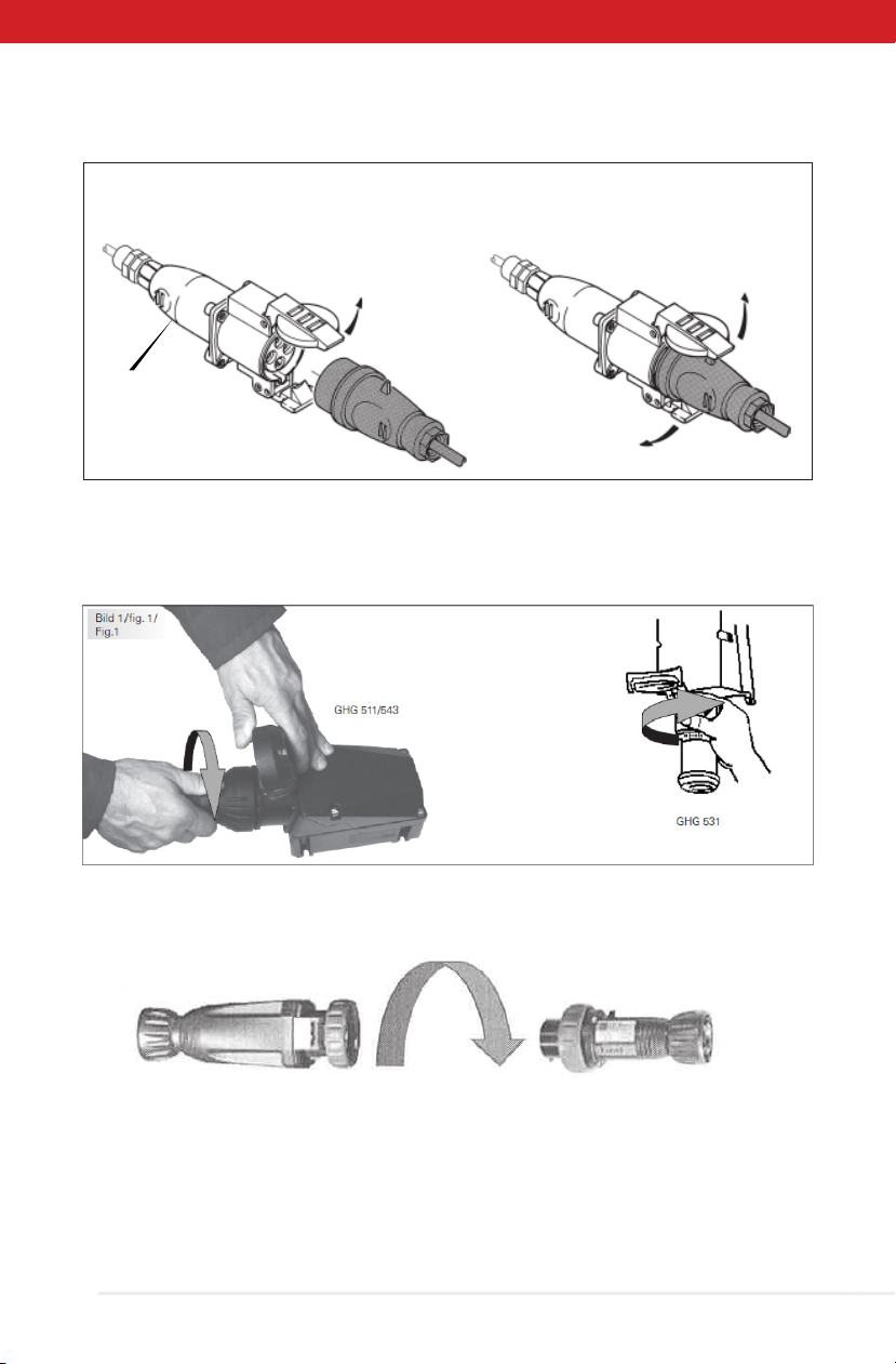
The power cables are built with three critical parts; Cable, Plug, and Couplers. Cables were
selected based on the need for extra heavy-duty applications. Plugs and couplers were
selected based on the most commonly used European connectors for hazardous locations.
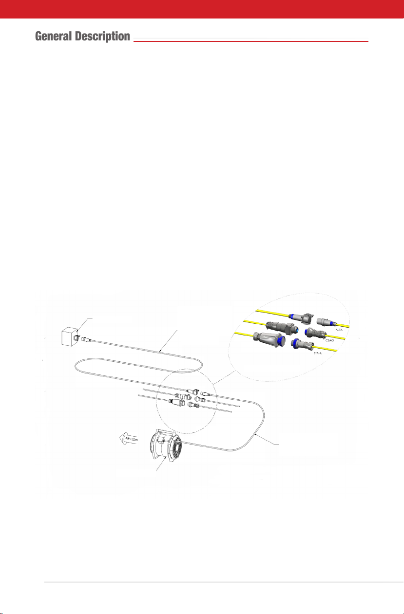
The drawing below depicts the ATEX / IECEx Power cable application, used to extend the
reach of a portable ATEX fan with H07RN-F cable and with three of the most popular brands
of A.T.X, CEAG, and R. Stahl, connectors.
The ATEX/IECEx Power Extension Cables are available for 110VAC or 240VAC power
requirements.
The Power Extension Cables have been certied to meet the ATEX Directive 2014/34/EU
certication for Ex de G D Ex de IIB, Zone 1, 2, 21, & 22.
25 POWER CORD,
H07RN-F FACTORY
INSTALLED
ATEX PLUG & COUPLER
PORTABLE FAN
POWER SOURCE
ATEX EXTENSION
POWER CORD.
3C, 1.5mm2, H07RN-F,
3C, 2.5mm2,H07RN-F,
OR 3C, 4mm2,H07RN-F

5
Part Number Table
PART NUMBER TABLE
(200-250VAC POWER CABLES)
H7 XX XXX2 XX
-
CABLE TYPE
XX -
H7 H07RN-F
WIRE SIZE
XX GAUGE
15 1.5 mm2
25 2.5 mm2
40 4.0 mm2
CONNECTION TYPE
XXX2 - -
ATX2 APPLETON 240V
STA2 STAHL 240V
CEA2 CEAG 240V
CABLE LENGTH (METERS)
XX -
01 1 m
02 2 m
↓ ↓
99 99 m
PART NUMBER TABLE
(FOR 110-130VAC POWER CABLES)
H7 XX XXX1 XX
-
CABLE TYPE
XX -
H7 H07RN-F
WIRE SIZE
XX GAUGE
15 1.5 mm2
25 2.5 mm2
40 4.0 mm2
CONNECTION TYPE
XXX1 - -
ATX1 APPLETON 110V
STA1 STAHL 110V
CEA1 CEAG 110V
CABLE LENGTH (METERS)
XX -
01 1 m
02 2 m
↓ ↓
99 99 m

6
• Determine operating voltage 110 or 230VAC.
• Determine conductor based on application. NOTE: 2.5 mm2 conductor size is most
common but can be supplied with 1.5 or 4 mm2 conductors.
• Determine brand and operating voltage for plug & couplers required to mate properly
with power source and electrical devices.
• Determine overall power extension cable length required for application. Use tables
here in as a guide to verify length needed will be appropriate. Verify power extension
cable length does not exceed the maximum length, based on the amount of current
required to run the electrical device.
Note: The power extension cables are designed to handle a maximum current of
16 amps. Use charts enclosed as a guide to verify cable lengths are acceptable.
Note: Maximum power extension cable lengths for AC synchronous motor
applications with a run current less or equal to 16 amps, must be determined by
the locked rotor current / motor start current of the motor.
• Select plug & coupler type.
Part Number Table

ATEX / IECEx POWER EXTENSION CABLES
H07RN-F 2.5mm2 CABLE
Maximum Cable Length Based on a Resistive AC Load Current
January 20,2020
MOTOR SPECIFICATIONS
VSOURCE
(volts, AC)
ILOAD CURRENT
(amps, AC)
VAC MIN
(volts, AC)
ATEX POWER EXTENSION CABLE, MAX. LENGTH & VOLTAGE DROP
H07RN-F
(Cable Size)
RCABLE-PWR-EXT
Ω /1000 ft
LCABLE-PWR-EXT
(length, meters)
VCABLE-DROP
(volts, AC)
110 VAC
110 VAC
110 VAC
110 VAC
110 VAC
110 VAC
110 VAC
110 VAC
110 VAC
110 VAC
110 VAC
110 VAC
110 VAC
110 VAC
110 VAC
110 VAC
1.0 AAC
2.0 AAC
3.0 AAC
4.0 AAC
5.0 AAC
6.0 AAC
7.0 AAC
8.0 AAC
9.0 AAC
10.0 AAC
11.0 AAC
12.0 AAC
13.0 AAC
14.0 AAC
15.0 AAC
16.0 AAC
93.5 VAC
93.5 VAC
93.5 VAC
93.5 VAC
93.5 VAC
93.5 VAC
93.5 VAC
93.5 VAC
93.5 VAC
93.5 VAC
93.5 VAC
93.5 VAC
93.5 VAC
93.5 VAC
93.5 VAC
93.5 VAC
230 VAC
230 VAC
230 VAC
230 VAC
230 VAC
230 VAC
230 VAC
230 VAC
230 VAC
230 VAC
230 VAC
230 VAC
230 VAC
230 VAC
230 VAC
230 VAC
1.0 AAC
2.0 AAC
3.0 AAC
4.0AAC
5.0 AAC
6.0 AAC
7.0 AAC
8.0 AAC
9.0 AAC
10.0 AAC
11.0 AAC
12.0 AAC
13.0 AAC
14.0 AAC
15.0 AAC
16.0 AAC
195.5 VAC
195.5 VAC
195.5 VAC
195.5 VAC
195.5 VAC
195.5 VAC
195.5 VAC
195.5 VAC
195.5 VAC
195.5 VAC
195.5 VAC
195.5 VAC
195.5 VAC
195.5 VAC
195.5 VAC
195.5 VAC
2.5 mm2
2.5 mm2
2.5 mm2
2.5 mm2
2.5 mm2
2.5 mm2
2.5 mm2
2.5 mm2
2.5 mm2
2.5 mm2
2.5 mm2
2.5 mm2
2.5 mm2
2.5 mm2
2.5 mm2
2.5 mm2
2.15 Ω/1000FT
2.15 Ω/1000FT
2.15 Ω/1000FT
2.15 Ω/1000FT
2.15 Ω/1000FT
2.15 Ω/1000FT
2.15 Ω/1000FT
2.15 Ω/1000FT
2.15 Ω/1000FT
2.15 Ω/1000FT
2.15 Ω/1000FT
2.15 Ω/1000FT
2.15 Ω/1000FT
2.15 Ω/1000FT
2.15 Ω/1000FT
2.15 Ω/1000FT
1170 m
585 m
390 m
292 m
234 m
195 m
167 m
146 m
130 m
117 m
106 m
97 m
90 m
84 m
78 m
73 m
2.5 mm2
2.5 mm2
2.5 mm2
2.5 mm2
2.5 mm2
2.5 mm2
2.5 mm2
2.5 mm2
2.5 mm2
2.5 mm2
2.5 mm2
2.5 mm2
2.5 mm2
2.5 mm2
2.5 mm2
2.5 mm2
2.15 Ω/1000FT
2.15 Ω/1000FT
2.15 Ω/1000FT
2.15 Ω/1000FT
2.15 Ω/1000FT
2.15 Ω/1000FT
2.15 Ω/1000FT
2.15 Ω/1000FT
2.15 Ω/1000FT
2.15 Ω/1000FT
2.15 Ω/1000FT
2.15 Ω/1000FT
2.15 Ω/1000FT
2.15 Ω/1000FT
2.15 Ω/1000FT
2.15 Ω/1000FT
16.50 VAC
16.50 VAC
16.50 VAC
16.50 VAC
16.50 VAC
16.50 VAC
16.50 VAC
16.50 VAC
16.50 VAC
16.50 VAC
16.50 VAC
16.50 VAC
16.50 VAC
16.50 VAC
16.50 VAC
16.50 VAC
2446 m
1223 m
815 m
612 m
489 m
408 m
349 m
306 m
272 m
245 m
222 m
204 m
188 m
175 m
163 m
153 m
34.50 VAC
34.50 VAC
34.50 VAC
34.50 VAC
34.50 VAC
34.50 VAC
34.50 VAC
34.50 VAC
34.50 VAC
34.50 VAC
34.50 VAC
34.50 VAC
34.50 VAC
34.50 VAC
34.50 VAC
34.50 VAC
7

ATEX / IECEx POWER EXTENSION CABLES
H07RN-F 4mm2 CABLE
Maximum Cable Length Based on a Resistive AC Load Current
MOTOR SPECIFICATIONS
VSOURCE
(volts, AC)
ILOAD CURRENT
(amps, AC)
VAC MIN
(volts, AC)
ATEX POWER EXTENSION CABLE, MAX. LENGTH & VOLTAGE DROP
Super-Trex
(Cable Size)
RCABLE-PWR-EXT
Ω /1000 ft
LCABLE-PWR-EXT
(length, meters)
VCABLE-DROP
(volts, AC)
110 VAC
110 VAC
110 VAC
110 VAC
110 VAC
110 VAC
110 VAC
110 VAC
110 VAC
110 VAC
110 VAC
110 VAC
110 VAC
110 VAC
110 VAC
1 AAC
2 AAC
3 AAC
4 AAC
5 AAC
6 AAC
7 AAC
8 AAC
9 AAC
10 AAC
11 AAC
12 AAC
13 AAC
14 AAC
15 AAC
93.5 VAC
93.5 VAC
93.5 VAC
93.5 VAC
93.5 VAC
93.5 VAC
93.5 VAC
93.5 VAC
93.5 VAC
93.5 VAC
93.5 VAC
93.5 VAC
93.5 VAC
93.5 VAC
93.5 VAC
230 VAC
230 VAC
230 VAC
230 VAC
230 VAC
230 VAC
230 VAC
230 VAC
230 VAC
230 VAC
230 VAC
230 VAC
230 VAC
230 VAC
230 VAC
1 AAC
2 AAC
3 AAC
4 AAC
5 AAC
6 AAC
7 AAC
8 AAC
9 AAC
10 AAC
11 AAC
12 AAC
13 AAC
14 AAC
15 AAC
195.5 VAC
195.5 VAC
195.5 VAC
195.5 VAC
195.5 VAC
195.5 VAC
195.5 VAC
195.5 VAC
195.5 VAC
195.5 VAC
195.5 VAC
195.5 VAC
195.5 VAC
195.5 VAC
195.5 VAC
4 mm2
4 mm2
4 mm2
4 mm2
4 mm2
4 mm2
4 mm2
4 mm2
4 mm2
4 mm2
4 mm2
4 mm2
4 mm2
4 mm2
4 mm2
1.41 Ω/1000FT
1.41 Ω/1000FT
1.41 Ω/1000FT
1.41 Ω/1000FT
1.41 Ω/1000FT
1.41 Ω/1000FT
1.41 Ω/1000FT
1.41 Ω/1000FT
1.41 Ω/1000FT
1.41 Ω/1000FT
1.41 Ω/1000FT
1.41 Ω/1000FT
1.41 Ω/1000FT
1.41 Ω/1000FT
1.41 Ω/1000FT
1783.9 m
891.9 m
594.6 m
446 m
356.8 m
297.3 m
254.8 m
223 m
198.2 m
178.4 m
162.2 m
148.7 m
137.2 m
127.4 m
118.9 m
2.5 mm2
2.5 mm2
2.5 mm2
2.5 mm2
2.5 mm2
2.5 mm2
2.5 mm2
2.5 mm2
2.5 mm2
2.5 mm2
2.5 mm2
2.5 mm2
2.5 mm2
2.5 mm2
2.5 mm2
16.5 VAC
16.5 VAC
16.5 VAC
16.5 VAC
16.5 VAC
16.5 VAC
16.5 VAC
16.5 VAC
16.5 VAC
16.5 VAC
16.5 VAC
16.5 VAC
16.5 VAC
16.5 VAC
16.5 VAC
3729.9 m
1864.9 m
1243.3 m
932.5 m
746 m
621.6 m
532.8 m
466.2 m
414.4 m
373 m
339.1 m
310.8 m
286.9 m
266.4 m
248.7 m
34.5 VAC
34.5 VAC
34.5 VAC
34.5 VAC
34.5 VAC
34.5 VAC
34.5 VAC
34.5 VAC
34.5 VAC
34.5 VAC
34.5 VAC
34.5 VAC
34.5 VAC
34.5 VAC
34.5 VAC
1.41 Ω/1000FT
1.41 Ω/1000FT
1.41 Ω/1000FT
1.41 Ω/1000FT
1.41 Ω/1000FT
1.41 Ω/1000FT
1.41 Ω/1000FT
1.41 Ω/1000FT
1.41 Ω/1000FT
1.41 Ω/1000FT
1.41 Ω/1000FT
1.41 Ω/1000FT
1.41 Ω/1000FT
1.41 Ω/1000FT
1.41 Ω/1000FT
8

9
1. Completely uncoil power extension cable as to be used between AC power source and
electrical device.
Inspect cable and connectors for damage or wear that could render the cable unsafe for
hazardous locations.
Route cable to avoid contact with heavy machinery that could possible damage cable or
possible be a trip hazard for workers. Cables must be integrated into a system in a way to
support accessibility for regular maintenance.
2. Connect plug end of the power extension cable to the AC power source.
3. Verify AC power source is providing an electrical ground connection.
4. Verify electrical device is turned OFF before attaching power extension cable.
5. Connect coupler end of cable to the electrical device.
Note: For ATX connectors lift dust covers and insert plug into coupler until coupler dust
cap latches snaps into position on plug. To break connection between coupler and plug lift
dust cap to pull connectors apart.
Note: For CEAG connectors lift dust cover, insert plug into coupler, and rotate clockwise, to
lock plug into coupler and to close power switch within the coupler. To break connection
between coupler and plug lift dust cap and rotate plug counter-clockwise to pull connectors
apart.
Note: For R.STAHL connectors insert plug into coupler and rotate outer ring clockwise to
secure plug to coupler.
See illustrations.
Installation Instruction and Care

10
CEAG Connector Installation and Removal
Euramco Safety has a number of optional anti-static/conductive airow duct accessories
designed explicitly for use with our Hazardous Location Fans to support various end user
applications as identied in the list below.
3/4
• Montage sur panneau ou enveloppe non protégée
• Mounting on a panel or on a not protected enclosurre
• Montage auf Tafel oder nicht geschütztes Gehäuse
• Montagem sobre painel ou caixa sem proteção
•Монтаж на щиток или на незащищенный корпус
• Extraction de la fiche
• removal of the plug
• Auseinanderrsetzen
• Remoção do plugue
•Извлечение штепселя
• Assemblage
• Insertion of the plug
• Zusammenbau
• Montagem
•Сборка
• Joint d’étanchéité
• Wheatherproof seal
• Dichtung
• Junta de vedação
•Изолирующая прокладка
16A : 1 - PG16
32A
1 - PG21 (3P + T)
1 - PG29 (3P + N + T)
• Panneau 3 mm maxi
• Panel, 3 mm th. max.
• Tafel : 3 mm max.
• Painel 3 mm máximo
•Макс. толщина двери шкафа 3мм.
• Respecter les affectations (R1, S2, T3, N et )
pour les raccordements des conducteurs
• Comply with the pin configuration (R1, S2, T3, N
and ) for the connection of the wires
• Die Merkzeichen einhalten (R1, S2, T3, N und ) für die
Leitungsansclüsse
• Respeitar as configurações do pino (R1, S2, T3 e T )
para a conexão dos fios condutores
•Соблюдайте обозначения (R1, S2, T3, N и)
для подключения проводов
A.T.X. Connector Installation and Removal
R. STAHL Connector Installation and Removal
Disconnect power before disassembly or cleaning. Never immerse or directly spray cable
and connectors with liquids. Clean cables with commercially available biodegradable clean-
ing solutions. Do not use solvents containing hydrocarbons (i.e. MEK, Acetone).
There are no user serviceable parts. Contact factory for replacement part applicability.
Do not change make or model number the power extension cables for any reason!
STAHL
Insertion & Removal

11
Cautions
The ATEX / IECEx Power Extension Cables are intended for use in Explosive Atmospheres in
accordance with ATEX Directive 2014/34/EU. It is the user's responsibility to determine the
suitability of the power extension cables for the intended purpose.
CAUTION! THESE POWER EXTENSION CABLES ARE NOT INTENDED FOR USE IN MINES
SUSCEPTIBLE TO FIREDAMP.
Do not operate if there is any physical damage to cord, plug or receptacle.
Fatal electrical shock may result if power extension cables are not grounded in compliance
with electrical code.
Keep away from children.
ATEX / IECEx Extension Cable Rating: Ex de G D Ex IIB, Zone 1, 2, 21, & 22
Euramco Safety hereby declares that the equipment listed in this manual conforms to the
relevant Essential Health and Safety Requirements of the European Machinery Directive
and standards listed below.
Standards to which conformity is declared: See Declaration of Conformity (last page).
The ATEX / IECEx Power Extension Cables complies with International Standards
EN 60079-0:2012+A11:2013, EN 60079-1:2014, EN 60079-7:2015, & EN60079-31:2014.
Category, Group and Zone Classications
According to ATEX Directive (2014/34/EU)
The power cables are built with three critical parts; Cable, Plug, and Couplers. The H07RN-R
and SOOW cables were selected based on the need for extra heavy-duty applications. Plugs
and couplers were selected based on the most commonly used European connectors for
hazardous locations.
The Power Extension Cables have been certied to meet the ATEX Directive 2014/34/EU
certication for Ex de G D Ex de IIB, Zone 1, 2, 21, & 22.
Accessories
None

12
Warranty
The ATEX / IECEx Power Extension Cables are warranted for one year form date of original
purchase, to be free of defects in material and workmanship. Misuse and normal tear and
wear are not covered under the warranty.
RAMFAN products are warranted against manufacture defect. Failure to properly maintain
power extension cables will invalidate warranty coverage. Please visit www.euramco.com
for warranty details.
How to maintain cable Maintenance
• Consult the relevant national regulations to determine the type and extent of
inspections.
• Adapt inspection intervals to the operating conditions.
At a minimum, check the following points during maintenance work on their device:
• Firm t of the conductors.
• Damage on the enclosure; seals or surface.
• Dirt on the sleeves.
• Compliance with the permissible temperatures (according to IEC/EN 60079).
• Whether the device is used in accordance with its intended use.
Cleaning
• To avoid electrostatic charging, the devices located in potentially explosive areas may
only be cleaned using a damp cloth.
• When cleaning with a damp cloth, use water or mild, non-abrasive, non-scratching
cleaning agents.
• Do not use aggressive detergents or solvents.
• Prevent water and cleaning agents from penetrating the socket contacts.
Disposal
• Observe national and local regulations and statutory regulation regarding disposal.
• Separate materials when sending it for recycling.
• Ensure environmentally friendly disposal of all components according to the statutory
regulations.
How to Maintain Cable

13
Declaration of Conformity
2746 Via Orange Way, Spring Valley, CA 91978 USA | T: +1 (619) 670-9590 |theteam@euramcosafety.com |•www.euramcosafety.com
May 3, 2019
ATEX / IECEx POWER EXTENSION CABLES
List of Applicable Harmonized Standards
UL Project Number 4788784924
STANDARDS TITLES
2014/34/EU ATEX Directive
2006/42-EC Machinery Directive
2014/30/EU Electromagnetic Compatibility Directive
2014/35/EU Low Voltage Directive
EN 60079-0:2012+A11:2013 Explosive Atmospheres. General Requirements
EN 60079-1:2014 Explosive Atmospheres – Part 1: Equipment Protection by Flameproof
Enclosures
EN 60079-7:2015 Explosive Atmospheres – Part 7: Equipment Protection by Increased
Safety “e”
EN 60079-31:2014 Amendment 1 – Explosive Atmospheres – Part 7: Equipment Protection
by Increased Safety “e”

Declaration of Conformity
Euramco Group | 2746 Via Orange Way, Spring Valley CA 91978 USA | Ph: +1-619-670-9590 | www.Euramco.com
Page 1 of 1
DECLARATION OF CONFORMITY
ATEX Certified Portable Fans
This Declaration of Conformity is issued for ATEX certified, flame proof, increased safety, portable fans,
intended for use in potentially explosive atmospheres, manufactured by Euramco Safety, Inc. as referenced
herein.
Issue Date: December 10, 2019
Manufacturer: Euramco Safety, Inc.
2746 Via Orange Way
Spring Valley, CA 91978 USA
Equipment Descriptions: UB20xx 8" / 20 cm ATEX Blower Exhauster
EFi75xx 12" / 30 cm ATEX Blower Exhauster
EFi120xx 16" / 40 cm ATEX Blower Exhauster
EFi150xx 16" / 40 cm ATEX Blower Exhauster
Hazardous Location Rating: II 2 G Ex db eb IIB T6 Gb
T6, non-mining gases up to 85˚C
Notified Body: UL International DEMKO A/S, Notified Body Number 0539
Borupvang 5A
2750 Ballerup, Denmark
Certification Number: DEMKO 09 ATEX 0926969X Rev. 3
Notification Number: 10 ATEX Q137286 Rev. 2
Standards to which
Certificate Applies: EN 60079-0:2018
EN 60079-1:2014
EN 60079-7:2015+A1:2018
EN 14986:2017
Self-Declared Compliance
Directives: 2006/42/EC –Machinery Directive
2014/35/EU –Low Voltage Directive
2014/30/EU –EMC Directive
2011/65/EU –RoHS –Reduction of Hazardous Substances Directive
Euramco Safety, Inc. hereby declares that equipment described above conforms with the protection
requirements of ATEX Council Directive 2014/34/EU on the approximation of the laws of the Member States
Concerning Equipment and Protection Systems Intended for use in Potentially Explosive Atmospheres.
Wayne Allen
President and CEO
14

15

020420
SINGAPORE
1 Fullerton Road
#02-01 One Fullerton
Singapore 049213
Tel : +65-9773 33 35
CHINA
A11, No. 1 Jinxi Road
Qingshuipu, Zhenhai, Zhejiang
Ningbo, China 315221
Phone: +86-574-87979390
Fax: +86-574-87979391
MIDDLE EAST – UAE
Jebel Ali FTZ, Dubai
Phone: +1 (619) 670-9590 x114
Fax: +1 (619) 670-7345
LUXEMBOURG
1 Rue Edmond Reuter,
5326 Contern, Luxembourg
Phone: +352-621377200
Fax: +352-26008056
USA
2746 Via Orange Way
Spring Valley, CA 91978 USA
Toll Free: (800) 472-6326
Phone: +1 (619) 670-9590
Fax: +1 (619) 670-7345
SM-ECXCABLES Rev A
This manual suits for next models
1
Table of contents
Other RAMFAN Cables And Connectors manuals
Popular Cables And Connectors manuals by other brands

Converters.TV
Converters.TV 1 by 8 HDMI to CAT6 Splitter Operation manual

NTI
NTI VOPEX-C5VA/C5V-x(C) Installation and operation manual

BDV
BDV DVI DL-DA Splitter Installation & operation guide

Monacor
Monacor HDMQS-1044K instruction manual

Fujitsu
Fujitsu UTY-XWZX installation manual

Aukey
Aukey CB-AL04 user manual