Rami TEL 300 User manual

FRANCAIS 2Rami - TEL 300/TEL 300S

Rami - TEL 300/TEL 300S 3FRANCAIS
SOMMAIRE
4
4
4
5
6
7
8
10
10
11
SUMMARY
[English...................................................................................
[Caractéristiques....................................................................
[Informations...........................................................................
[ .............................................................................Synoptique
[ .............................................................................Utilisation..
[ .............................................................................Description
[ .............................................................................Face avant
[ ..........................................................................Face arrière.
[ ......................................................................Mise en oeuvre
[................................................................................Câblage

FRANCAIS 4Rami - TEL 300/TEL 300S
Le TEL 300 peut s'adapter à n'importe quel type de console disposant d'une voie spécifique (
N - 1 ), comme la COMPACT II ou la RP 2000S. L'utilisation d'un départ auxiliaire peut être une
alternative pour les consoles ne disposant pas de voie spécifique.
Le TEL 300 permet :
D'effectuer un enregistrement à l'aide de la sortie mixée qui comprend l'envoi vers le
correspondant (micro ou ligne) et le retour correspondant.
L'utilisation d'un filtre passe bande sur le départ correspondant permet de se conformer au
gabarit des réseaux tout en améliorant le taux de réjection anti local.
Toutes les entrées / sorties sont au standard symétrique sur XLR.
La mise ON AIR de l'insert peut s'effectuer soit en face avant soit en télécommande sur la
console.
Le câblage Télécom est normalisé en connecteur RJ11 (sortie du combiné sur deux RJ11 au
choix pour s’adapter aux deux standards en vigueur)
Le TEL 300 version S possède en plus la fonction de décrochage et raccrochage automatique.
[D'envoyer le signal de la table vers le correspondant.
[De mélanger les interventions du correspondant au signal de la table.
[De faire la commutation entre le poste téléphonique privé et l'insert.
[D'envoyer des ordres vers le correspondant.
[D'écouter uniquement le correspondant.
[
[Insert téléphonique classique pour jeux, débats ou conférence.
[Utilisation en cabine journaliste, pour réaliser des " papiers ". Il suffit seulement de rajouter un
microphone, un casque et une machine d'enregistrement.
[En version TEL 300S avec le décrochage automatique, pour effectuer une intervention à
distance ou se connecter sur un réseau d'ordres.
DESCRIPTION
UTILISATION
SYNOPTIQUE
+
+
+
+
FRONT
MICRO IN
REAR
MICRO IN
LINE IN
PHONE
LINE
EXT
REMOTE
RECEIVER
MIX OUT
RETURN
OUT
HEADPHONES
RFI
FILTERS
OPTION
INSERT
SWITCH
MIC
SENS
SEND
LEVEL
LEVEL
LIMITOR
BYPASS
800 HZ
LFO
SEND VUMETER
RETURN VUMETER
PEAK
LIMITOR
AUTOMATIC
ANALOG
HYBRID
MUTE
MUTE
HANG OFF
DETECTION
HYBRID
COMMAND
CALL
DETECTION
MIC
LINE
SEND
CALL
R Z
RETURN
ON / OFF
OPTION
OPTION
OPTION
OPTION

Rami - TEL 300/TEL 300S 5FRANCAIS
ANALOG HYBRID
CALIBRATION
R Z
TEST
MICRO INPUT SELECT
RETURN
SEND
INPUT LINE ADJUST
800Hz
LEVEL
PEAK
SENS
+
-
RETURN
SEND
LEVEL
+
-
VOLUME
10
0
+
+dB
+3
-3-6
-18 -12
-dB
OPHONES
TEL 300
LINE
MIC
PEAKMETER
PUSH TO INSERT
CALL INDICATOR
PUSH
23
12
4
5
6
14
13
8 9
10 11
7
15
16
1
1 ) oin
2 )
3 )
4 )
5 )
6 )
7 )
8 )
9 )
10 )
11 )
12 )
Entrée Micro sur embase XLR 3 p ts femelle. (De -56 dBu à -26 dBu ) (Alimentation
Fantôme intégrée)
Réglage de la sensibilité de l'entrée micro de face avant et face arrière. Variable de -56
dBu à -26 dBu.
Led de visualisation de la saturation de l'étage d'entrée micro.
Sélecteur du signal d'entrée : (Micro ou Ligne).
Led de visualisation de la commutation d'entrée en ligne.
Led de visualisation de la commutation d'entrée en micro.
Potentiomètre de volume du signal d'envoi ("SEND").
Potentiomètre de volume du signal de retour ("RETURN").
Mise en service du générateur interne de test 800 Hz pour le calibrage de la ligne.
Commutateur "TELEPHONE / INSERT" pour la prise de ligne et voyant d'APPEL.
Réglage de l'accord antilocal de la ligne ( R ).
Réglage de l'accord antilocal de la ligne ( Z ).
Vu-mètre de contrôle de la modulation de retour.
u-mètre de contrôle de la modulation de départ.
15 ) Potentiomètre de volume de l'écoute casque.
16 ) Embase Jack 6.35mm pour contrôle casque. (Ecoute mixée du départ et du retour).
13 )
14 ) V
FACE AVANT

FRANCAIS 6Rami - TEL 300/TEL 300S
G
HB
C
D
E
FA
REMOTES
LINE PHONE MIX
RETURN ONLY
LINE MICRO
Std A Std B
T 250mA L
230V 50/60Hz 12W
Made in Europe (Fr)
TRANSFORMERS
OUTPUTS
INPUTS
MODEL
TEL 300 S
TEL 300
TELEPHONE OUTPUTS INPUTS
PUSH PUSH
A) Entrée Micro sur embase XLR 3 pts femelle. (de -56 dbu à -26 dBu ) (Alimentation Fantôme
intégrée).
Attention : Ne pas brancher simultanément de micro en face avant et en face arrière.
B ) Entrée Ligne monophonique symétrique sur embase XLR 3pts femelle. (+6dBu)
C) Sortie monophonique symétrique ("SIGNAL CORRESPONDANT" uniquement) sur
embase XLR 3 points mâle.
D ) Sortie monophonique symétrique ("MIXAGE du départ et du retour correspondant") sur
embase XLR 3 points mâle.
E ) Embase RJ11 pour le branchement du poste téléphonique.
F ) Embase RJ11 pour la connexion avec le réseau téléphonique.
G ) Télécommande externe du TEL300 sur embase SUB-D15 femelle :
Télécommande de la prise de ligne : Placer un commutateur entre les broches 1 et 2.
Retour voyant de la prise de ligne (confirmation) : Câbler le voyant entre les broches 1
et 3.
[
[
[L' entrée ligne symétrique et la sortie symétrique "SIGNAL CORRESPONDANT" sont
maintenant accessibles sur le connecteur REMOTE (DB15).
Attention : ne pas utiliser en même temps les entrées/sorties sur XLR et celles sur la
Sub-D 15.
H ) Embase secteur
1
8
9
15
Lampe 24V/20mA
Boucle (maintenue)
Point chaud 7
Point chaud 13
GND 8
GND 14
Point froid 15
Point froid 6
LINE IN
LINE OUT
RETURN ONLY
+-
Sub-D 15 pts
mâle
FACE ARRIERE

[
[
[
[
[
[
[
[
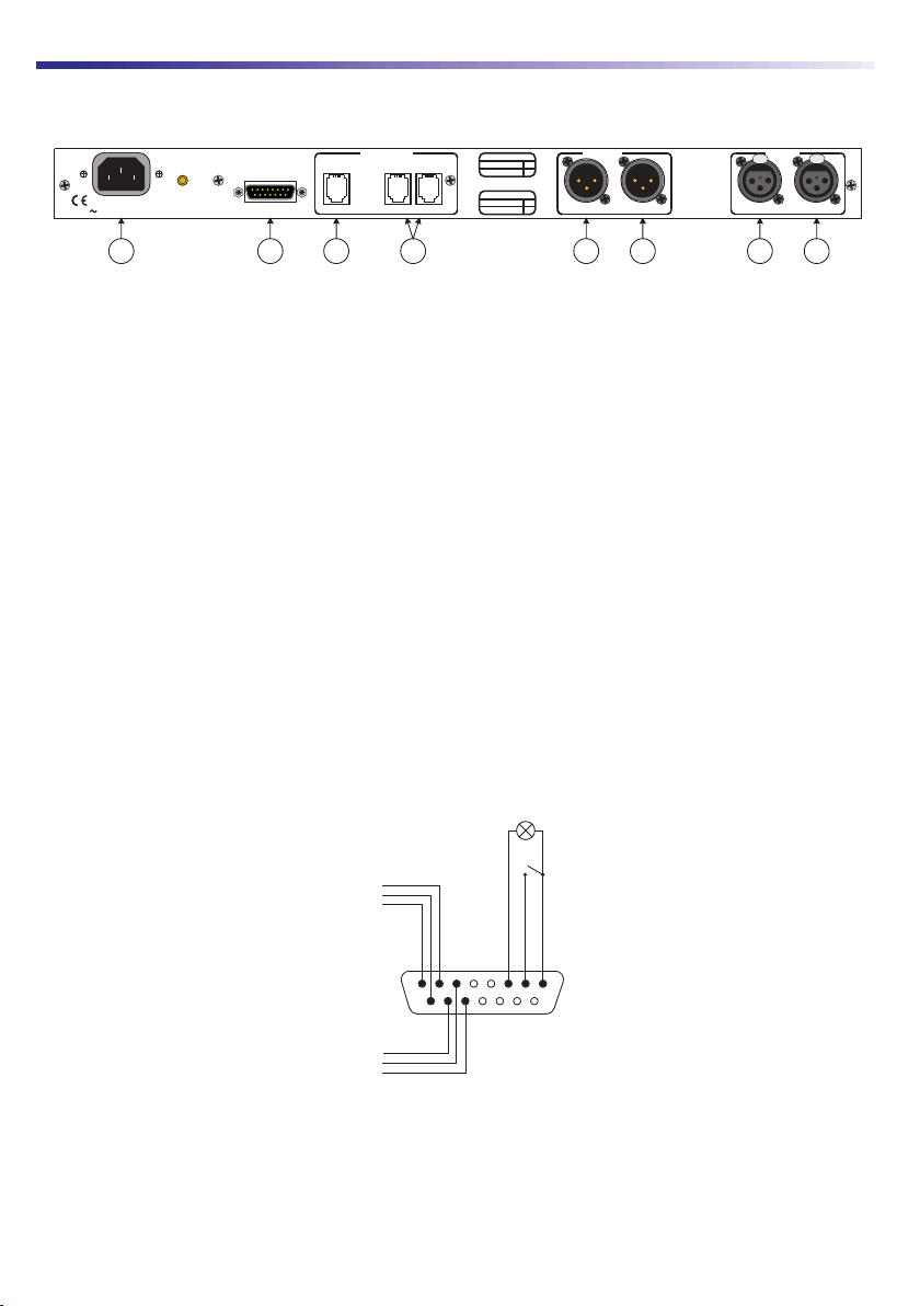
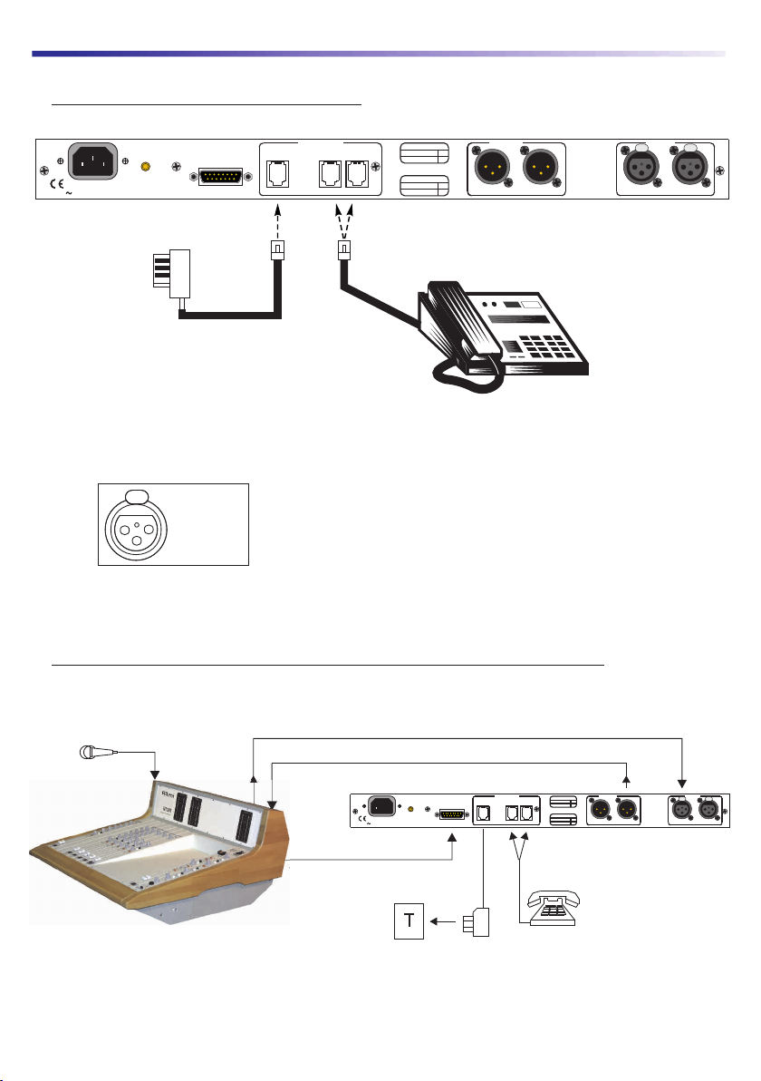
Connecter le TEL 300 conformément au câblage donné (Câblage 1 ou 2 suivant
configuration).
Appeler votre premier correspondant à l'aide du poste téléphonique (commutateur 10 au
repos).
Prendre la ligne à l'aide du commutateur 10.
Ajustement de la ligne. Cette opération est à effectuer une fois pour toute, car elle permet
d'adapter l'insert à votre standard
régional. On peut toutefois vérifier le réglage de temps en temps. Cette procédure consiste à
éliminer le plus possible du "retour correspondant", le signal envoyé vers celui-ci.
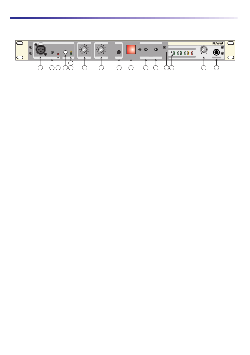
Mettre le volume 7 "départ modulation" à zéro.
Agir sur le commutateur 9"générateur test" position enfoncée (le signal est calibré et
indépendant du volume 7"départ de modulation").
Le vumètre 14 indique un niveau 0 dB.
Agir sur le volume 8"retour correspondant" de façon à visualiser un niveau 0 dB sur le
vumètre 13.
Régler alternativement les potentiomètres 11 et 12 d'ajustement de ligne, de façon à obtenir
sur le vumètre 13, le niveau le plus faible possible. On peut alors retoucher au volume 8pour
augmenter la sensibilité, et rerégler les potentiomètres 11 et 12 (Il est à noter qu'il existe une
position d'équilibre pour les potentiomètres 11 et 12 et que ceux-ci sont interactifs); une fois le
réglage optimisé, relâcher le commutateur 9"générateur test".
L'insert TEL 300 est maintenant adapté à votre ligne et peut ainsi fonctionner de façon
optimum.
[
[
UTILISATION
Passage du correspondant à l'écoute. Il est d'abord nécessaire d'envoyer le signal de la
console vers le correspondant; régler le volume 7"départ modulation" à l'aide du vumètre 14
et régler le volume 8"retour correspondant" à l'aide du vumètre 13 .
L'envoi d'ordres vers le correspondant est possible à l'aide de l'entrée micro ou line mono et
du volume 7"départ modulation vers le correspondant".
L'écoute du correspondant seul est possible à l'aide de la sortie C(contrôle pour le studio ).
L'écoute du correspondant et de l'envoi est possible à l'aide de la sortie D(enregistrement).
L'allumage du commutateur 10 signale un appel.
L'entrée B reçoit la sortie de console (sortie "SEND" de la console Compact ou RP2000).
La sortie Cse dirige vers l'exploitation.
OPTION : (TEL 300S) PRISE DE LIGNEAUTOMATIQUE
Dans le cadre d'une utilisation à distance, par exemple, le TEL300S peut prendre la ligne
automatiquement dès qu'un appel se présente, et raccroche ensuite dès la fin de cet appel.
Le commutateur 10 doit être alors en position relâchée, pour autoriser le mode automatique.
Dans ce cas seulement, le TEL300S prend la ligne au bout de 4 sonneries.
Le raccrochage peut ensuite s'effectuer de plusieurs façons possibles :
En utilisation normale, dès que la tonalité de raccrochage apparaît, le TEL 300S raccroche au
bout de 9 tonalités.
Dans le cas où l'on ne voudrait pas que la tonalité de raccrochage s'entende, il est possible de
commander à distance le raccrochage en appuyant sur les touches «*» puis «0» dans l'ordre.
En appuyant sur le commutateur 10, un opérateur peut à tout moment reprendre le contrôle
du TEL 300S, le remettant ainsi en mode normal; la position relâchée de cette touche forcera
alors le raccrochage du TEL 300S.
[
[
[
[
[
[
[
[
[
[
Rami - TEL 300/TEL 300S 7FRANCAIS
MISE EN OEUVRE

VERS LE RESEAU
TELECOM
POSTE
TELEPHONIQUE
MICRO D'ORDRE ENVOI
TEL 300
RETOUR CORRESPONDANT
TELECOMMANDE EXTERNE
REMOTES
LINE PHONE MIX
RETURN ONLY
LINE MICRO
Std A Std B
T 250mA L
230V 50/60Hz 12W
Made in Europe (Fr)
TRANSFORMERS
OUTPUTS
INPUTS
MODEL
TEL 300 S
TEL 300
TELEPHONE OUTPUTS INPUTS
PUSH PUSH
1 ) Raccordement sur la ligne téléphonique
REMOTES
LINE PHONE MIX
RETURN ONLY
LINE MICRO
Std A Std B
T 250mA L
230V 50/60Hz 12W
Made in Europe (Fr)
TRANSFORMERS
OUTPUTS
INPUTS
MODEL
TEL 300 S
TEL 300
TELEPHONE OUTPUTS INPUTS
PUSH PUSH
Attention ! suivant le type d'appareil
téléphonique utilisé, le câblage du cordon
n'est pas identique.
Le TEL 300 dispose donc de 2 standards
de connexion pour pallier à ce problème.
Connecter la ligne téléphonique
sur les points 1 et 3 du
conjoncteur. L'ordre des fils n'a
pas d'importance.
PUSH
1
2
3
1: Masse
2: Pt chaud
3: Pt froid
2 ) Exemple de câblage avec une console de radiodiffusion (Type RP 2000)
FRANCAIS 8Rami - TEL 300/TEL 300S
CABLAGE

POSTE TELEPHONIQUE
POUR LA NUMERATION
TEL 300
RETOUR VERS
STUDIO
MICRO JOURNALISTE
SORTIE MIX POUR L'ENREGISTREMENT
VERS LE RESEAU
TELECOM
MAGNETOPHONE
REMOTES
LINE PHONE MIX
RETURN ONLY
LINE MICRO
Std A Std B
T 250mA L
230V 50/60Hz 12W
Made in Europe (Fr)
TRANSFORMERS
OUTPUTS
INPUTS
MODEL
TEL 300 S
TEL 300
TELEPHONE OUTPUTS INPUTS
PUSH PUSH
3 ) Exemple de câblage pour l'enregistrement (interview) en production sans console
Rami - TEL 300/TEL 300S 9FRANCAIS
Suite
CABLAGE

FRANCAIS 10 Rami - TEL 300/TEL 300S
L'alimentation du TEL 300 / TEL 300S dispose d'un connecteur d'alimentation d'énergie (2 pôles +
terre). La terre doit être impérativement reliée au réseau d’énergie.
[Ne jamais faire fonctionner cet équipement sans le raccordement à la terre.
[Assurez-vous de la qualité de la terre avant la mise en route.
[Dans le cas d'éventuelles apparitions de bruit, de ronflement en connectant l'appareil sur une
sonorisation existante, ne jamais interrompre le connecteur terre de protection, mais utilisez des
équipements d'isolation galvanique à transformateurs.
[Ne jamais démonter l'équipement, sans avoir pris la précaution de débrancher le cordon
d’alimentation.
[Eviter l'exposition à de trop fortes températures.
[Ne jamais exposer l'alimentation et l'appareil à la pluie, la neige ou à l'humidité.
[Le TEL 300 / TEL 300S dispose d'un amplificateur pour casque, évitez les niveaux importants
ou les expositions prolongées capables d'endommager l'ouïe de façon irréversible.
Le TEL 300 / TEL 300S est conforme aux normes suivantes :
EN60065, EN55013, EN55020, EN60555-2, et EN60555-3, d'après les dispositions de la
directive73/23/EEC, 89/336/EEC et 93/68/EEC
Attention !!!
Alimentation : 230 Volts + / - 10 % 50 / 60 Hz
Dimensions :Rack 1 unité / 1 unit Rack
483 x 44 x 230 mm
Poids : 3,5 kg
Protections RFI sur toutes les entrées / sorties audio, l'entrée de télécommande, et
l'entrée secteur.
+6 dBu / 1,55 V
+6 dBu / 1,55 V
0 dBu / 0,775 V
XLR
JACK
XLR Symétrique
Symétrique
Asymétrique
Sorties Connecteur Type Impédance Niveau nominal
+26 dBu / 15,5 V
+26 dBu / 15,5 V
+20 dBu / 7,75 V
Niveau maximum
Correspondant
uniquement
47 Ohms
220 Ohms
27 Ohms
Mixage
envoi et retour
Casque
+6 dBu / 1,55 V +24 dBu / 12,28 V
+12 dBu / 3,09
-42 dBu / 6,16 mV
V
-10 dBu / 0,25 V
33 kOhms
1,2 kOhms
4.7 kOhms
Microphone
Ligne audio
Ligne Télécom
XLR
XLR
RJ 11
Symétrique
Symétrique
Symétrique
Sens mini : -26 dBu / 39 mV
Sens maxi : -56 dBu / 1,2 mV
Entrées Connecteur Type Impédance Sensibilité Saturation
Connecteurs:
ENTREE/SORTIEAUDIOtypeXLR
ENTREE/SORTIETELEPHONEpriseRJ11
Alimentation:
230Volts+/-10%
Dimensions:
Rack1unité
Faceavant:
483X44mm
Profondeur
230mmhorsconnecteurs
Profondeur
300mmavecconnecteurs
Poids:
3,5kg
Dimensionscolisage:
650x315x85mm
Poidscolisage:
4,5kg
CâblageXLR
:
1-MASSE
2-PtCHAUD
3-PtFROID
CARACTERISTIQUES
INFORMATIONS

12
12
12
13
14
15
16
18
18
Rami - TEL 300/TEL 300S 11 ENGLISH
SUMMARY
[ .......................................................................Specifications.
[Informations...........................................................................
[ ........................................................................Block diagram
[ .............................................................................Uses..........
[ .............................................................................Description
[ .............................................................................Front panel
[ ............................................................................Rear panel.
[ .....................................................................Implementation.
[ .......................................................................Wiring diagram

ENGLISH 12 Rami - TEL 300/TEL 300S
TEL 300 can be adapted to any type of console equipped with a specific channel (N - 1) , such as
COMPACT or RP 2000.The use of an auxillary send can be an alternative for consoles that do not
have a specific channel.
With TEL 300 you can:
[Send the signal from the desk to the correspondent.
[Mix the caller’s interventions with the signal from the desk.
[Switch between the private telephone line to the hybrid.
[Send instructions to the caller.
[Listen to the caller only.
The use of a band-pass filter on the caller's send allows it to conform to the calibre of the networks
whilst improving the antilocal reinjection rate.
All the inputs / outputs are XLR balanced.
The ON AIR switching can be done either on the front panel or by remote control from the
console.
Standard telecom wiring on RJ11 socket.
TEL 300S allow the automatic connection and disconnection of the phone line.
[Classic telephone insert for games, debates or conferences.
[Use in the press room to create "documents". The only requirements are a microphone,
headphones and a recording unit.
[The TEL 300S version has the automatic switching to carry out long distance interventions or
to connect on to an order network.
DESCRIPTION
USES
BLOCK DIAGRAM
+
+
+
+
FRONT
MICRO IN
REAR
MICRO IN
LINE IN
PHONE
LINE
EXT
REMOTE
RECEIVER
MIX OUT
RETURN
OUT
HEADPHONES
RFI
FILTERS
OPTION
INSERT
SWITCH
MIC
SENS
SEND
LEVEL
LEVEL
LIMITOR
BYPASS
800 HZ
LFO
SEND VUMETER
RETURN VUMETER
PEAK
LIMITOR
AUTOMATIC
ANALOG
HYBRID
MUTE
MUTE
HANG OFF
DETECTION
HYBRID
COMMAND
CALL
DETECTION
MIC
LINE
SEND
CALL
R Z
RETURN
ON / OFF
OPTION
OPTION
OPTION
OPTION

Rami - TEL 300/TEL 300S 13 ENGLISH
ANALOG HYBRID
CALIBRATION
R Z
TEST
MICRO INPUT SELECT
RETURN
SEND
INPUT LINE ADJUST
800Hz
LEVEL
PEAK
SENS
+
-
RETURN
SEND
LEVEL
+
-
VOLUME
10
0
+
+dB
+3
-3-6
-18 -12
-dB
OPHONES
TEL 300
LINE
MIC
PEAKMETER
PUSH TO INSERT
CALL INDICATOR
PUSH
23
12
4
5
6
14
13
8 9
10 11
7
15
16
1
1 ) Female 3 pt jack for mic input (from -56 dBu to -26 dB ) (integrated phantom supply)
2 ) Adjustment of the mic input sensitivity on the front panel and the back panel. Variable from
-56 dBu to -26 dBu.
3 ) Led display showing the clipping of the mic input stage
4 ) Selector of the input signal: (mic or line).
5 ) Led display showing the switching of the line input.
6 ) Led display showing the switching of the mic input.
7 ) Volume potentiometer for the send signal.
8 ) Volume potentiometer for the return signal .
9 ) Enabling of the test 800 Hz internal generator for the calibration of the line.
10 ) TELEPHONE / INSERTswitch for taking a line and the call indicator.
11 ) Adjustment of the antilocal tuning of the line ( R ).
12 ) Adjustment of the antilocal tuning of the line( Z ).
13 ) Control vu-meter for the return modulation.
14 ) Control vu-meter for the send modulation.
15 ) Volume potentiometer for the monitoring headphone.
16 ) TSR female jack for monitoring headphones. (Mixed monitoring of send / return).
FRONT PANEL

ENGLISH 14 Rami - TEL 300/TEL 300S
G
HB
C
D
E
FA
REMOTES
LINE PHONE MIX
RETURN ONLY
LINE MICRO
Std A Std B
T 250mA L
230V 50/60Hz 12W
Made in Europe (Fr)
TRANSFORMERS
OUTPUTS
INPUTS
MODEL
TEL 300 S
TEL 300
TELEPHONE OUTPUTS INPUTS
PUSH PUSH
A)
B )
Mic input on 3 pt XLR female jack. From -56 dbu to -26 dBu ) (Integrated phantom supply)
Balanced monophonic line input on XLR 3 pt female jack. (+6dBu)
C) Balanced monophonic output (correspondent's signal only) on 3 pt XLR jack.
D ) Balanced monophonic output (mixing of the correspondent's send / return) on 3 pt XLR jack.
E ) RJ11 jack to plug in the telephone.
F ) RJ11 jack for connection to the telephone network.
G ) TEL300 external remote control on female SUB-D15 jack:
[Remote control for taking a line : Put a switch between pins 1 and 2.
[Return indicator for taking a line (confirmation) : Wire up the indicator between pins 1
and 3.
[Now, balanced line input and balanced output “correspondent’s signal” are accessible
on the REMOTE connector (DB15).
Mains connector
Warning : Do not plug the mic in the front and the back at the same time.
Warning : Don’t use in the same time XLR input/output and Sub-D 15 input/output.
H )
1
8
9
15
Indicator 24V/20mA
Loop
Signal 7
Signal 13
GND 8
GND 14
Return 15
Return 6
LINE IN
LINE OUT
RETURN ONLY
+-
Sub-D 15 pts
male
REAR PANEL

Rami - TEL 300/TEL 300S 15 ENGLISH
[Connect the TEL 300 according to the wiring given (Wiring 1 or 2 depending on
configuration).
[Call your first correspondent using the telephone (switch 10 on standby).
[Take the line using switch 10.
[Adjustment of the line (this operation is carried out only once as it allows the insert to be
adapted to your local switchboard (the adjustment can be checked from time to time). This
procedure consists of eliminating, as much of the signal sent to the correspondent as
possible from the correspondent's return.
[Put volume 7« send modulation » to zero.
[Press down switch 9« test generator » (the signal is calibrated and independent of volume 7
SEND MOD.).
[Vu-meter 14 shows a level 0dB.
[Adjust volume 8«return correspondent» so as to attain a O dB level on vu-meter 13.
[Adjust in alternation the line adjustment potentiometers 11 and 12 so as to obtain the lowest
level possible on vu-meter 13. One can then alter volume 8 to increase the sensitivity and
readjust the potentiometers 11 and 12 (It must be noted that the potentiometers 11 and 12
have a position of balance and that they are interactive); once the optimum adjustment is
reached release the « test generator » (switch 9).
[The TEL 300 insert is now adapted to your line and is fully functional.
USE
[To switch the correspondent over to monitor, it is first necessary to send a signal from the
console to the correspondent; adjust volume 7« send modulation » using vu-meter 14 and
adjust volume 8 « return correspondent » using the vu-meter 13.
[It is possible to send instructions to the correspondent using mic input or line mono and
volume 7« send modulation to the correspondent ».
[Monitoring only the correspondent is possible using C output. (Control for the studio).
[Monitoring the correspondent and sending is possible using the Doutput (recording).
[Lighting up of switch 10 signals an incoming call.
[Input Breceives console output (send console Compact or RP2000).
[The Coutput goes to the operation.
OPTION : (TEL 300S) AUTOMATIC LINE PICK UP
When being used at a distance, for example, the TEL300S can take a call automatically as soon
as it comes in and then hang up at the end of the call.
Switch 10 must be in release position so as to allow the automatic mode to function; only in this
case will the TEL300S take the call after 4 rings.
Hanging up after the call can done in several ways:
[In normal use, the TEL 300S will let the hang up tone ring 9 times before actually hanging up.
[Where one would like to avoid this tone being heard it is possible to control the hanging up
from a distance by pressing keys « * » then « 0 » in that order.
[By pressing switch 10 an operator can at any time take back control of the TEL 300S thus
returning it to normal mode; the release position of this key will force the hanging up of the
TEL300S.optimum.
IMPLEMENTATION

TO TELEPHONE
NETWORK
TELEPHONE
ORDER MIC SENDING
TEL 300
CORRESPONDENT RETURN
EXTERNAL REMOTE
REMOTES
LINE PHONE MIX
RETURN ONLY
LINE MICRO
Std A Std B
T 250mA L
230V 50/60Hz 12W
Made in Europe (Fr)
TRANSFORMERS
OUTPUTS
INPUTS
MODEL
TEL 300 S
TEL 300
TELEPHONE OUTPUTS INPUTS
PUSH PUSH
1 ) Wiring with phone line
REMOTES
LINE PHONE MIX
RETURN ONLY
LINE MICRO
Std A Std B
T 250mA L
230V 50/60Hz 12W
Made in Europe (Fr)
TRANSFORMERS
OUTPUTS
INPUTS
MODEL
TEL 300 S
TEL 300
TELEPHONE OUTPUTS INPUTS
PUSH PUSH
Warning ! TEL 300 own 2 connectors for
differents phones strand.
Connect the phone line on circuit
closer 1 and 3 points.
PUSH
1
2
3
1: Ground
2: Signal
3: Return
2 ) Example of wiring using a broadcast console (type Rp2000)
ENGLISH 16 Rami - TEL 300/TEL 300S
WIRING DIAGRAM

TELEPHONE FOR
DIALINGN
TEL 300
STUDIO RETURN
JOURNALIST’S MIC
MIX OUTPUT FOR RECORDING
TO TELEPHONE
NETWORK
RECORDER
REMOTES
LINE PHONE MIX
RETURN ONLY
LINE MICRO
Std A Std B
T 250mA L
230V 50/60Hz 12W
Made in Europe (Fr)
TRANSFORMERS
OUTPUTS
INPUTS
MODEL
TEL 300 S
TEL 300
TELEPHONE OUTPUTS INPUTS
PUSH PUSH
3 ) Example of wiring for a recording (interview) in production without a console
Rami - TEL 300/TEL 300S 17 ENGLISH
Next
WIRING DIAGRAM

ENGLISH 18 Rami - TEL 300/TEL 300S
TEL 300 / TEL 300S mains connector has three wires (2 poles + earth). Earth should imperatively
be connected to mains earth.
[Never use this equipement without proper grounding.
[Check quality of grounding.
[Should noise or hum occurs when connected to other equipments, never disconnect
grounding, use insulating transformer on mains.
[Never open the case without disconnecting mains
[Avoid high temperature exposure.
[Never expose the equipment to rain, snow or moisture.
[Using TEL300 / TEL 300S headphone amplifier, listening to high level can result in
permanent damage to ears.
TEL 300 / TEL 300S complies with :
En60065, EN55013, EN55020, EN60555-2, et EN60555-3, according to 73/23/EEC,
89/336/EEC et 93/68/EEC
Warning !!!
Power supply : 230 Volts + / - 10 % 50 / 60 Hz
Dimensions :Rack 1 unité / 1 unit Rack
483 x 44 x 230 mm
Weight : 3,5 kg
RFI protections on all audio inputs/outputs, remote control input and mains input.
+6 dBu / 1,55 V
+6 dBu / 1,55 V
0 dBu / 0,775 V
XLR
JACK
XLR Balanced
Balanced
Unbalanced
Outputs Connector Type Impedance Nominal Level
+26 dBu / 15,5 V
+26 dBu / 15,5 V
+20 dBu / 7,75 V
Maximum Level
Correspondent
only
47 Ohms
220 Ohms
27 Ohms
Mixing of send
and return
Headphone
+6 dBu / 1,55 V +24 dBu / 12,28 V
+12 dBu / 3,09
-42 dBu / 6,16 mV
V
-10 dBu / 0,25 V
33 kOhms
1,2 kOhms
4.7 kOhms
Microphone
Audio line
Telephone line
XLR
XLR
RJ 11
Balanced
Balanced
Balanced
Sens mini : -26 dBu / 39 mV
Sens maxi : -56 dBu / 1,2 mV
Inputs Connector Type Impedance Sensitivity Distorsion
Connecteurs:
ENTREE/SORTIEAUDIOtypeXLR
ENTREE/SORTIETELEPHONEpriseRJ11
Alimentation:
230Volts+/-10%
Dimensions:
Rack1unité
Faceavant:
483X44mm
Profondeur
230mmhorsconnecteurs
Profondeur
300mmavecconnecteurs
Poids:
3,5kg
Dimensionscolisage:
650x315x85mm
Poidscolisage:
4,5kg
CâblageXLR
:
1-MASSE
2-PtCHAUD
3-PtFROID
SPECIFICATIONS
INFORMATIONS

1081209
Rami se réserve le droit de modifier les spécifications du produit sans préavis / All specification in this document can be modifed by RAMI without prior notice
Tél. : 33 (0)1 64 66 20 20- Fax : 33 (0)1 64 66 20 30
7 Rue Raoul Follereau
77600 BUSSY SAINT GEORGES - FRANCE
www.ramiaudio.com
This manual suits for next models
1
Table of contents
Languages:
Other Rami Telephone manuals