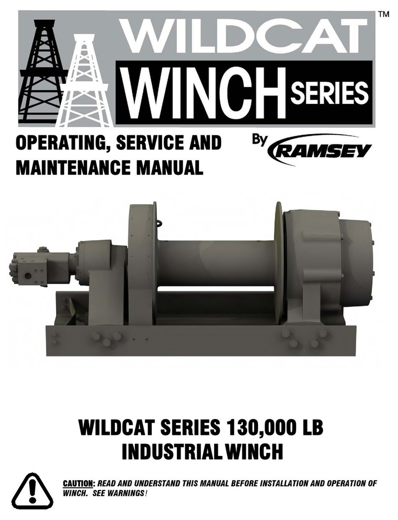
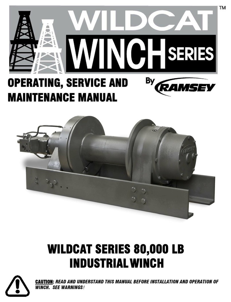
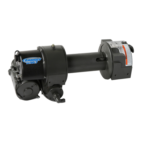
Ramsey Electronics 2000 User manual

Ramsey
Winch
Company
OWNERS
MANUAI
Front
iViount
Electric
Winch
Model
2000
with
Hawse
Type
Falrleads*
Model
2001
with
Roller
Type
Fairleads*
Model
7901
with
Roller
Type
Fairlead*
V
/
)
Zi
I
'"Mk
^/UUiM
^
J
-
(y
'
Now
Equipped
with
RAM-LOK
clutch
MODEL
2000
with
Hawse
Type
Falrleads
MODEL
2001
with
Roller
Type
Fairlead
Congratulations
You
have
purchased
the
finest
winch
avail
able
in
its
service
class.
It
was
designed
and
manufactured
to
provide
you
with
the
utmost
in
fun
and
utility.
The
new
RAM-LOK
clutch
gives
you
easier
free
spooling
and
positive
clutch
engagement
for
greater
convenience.
As
with
any
device
that
com
bines
power
and
movement
in
its
use,
there
are
dangers
if
improperly
used.
At
the
same
time,
there
are
easier
and
faster
ways
for
getting
the
job
done
if
certain
precautions
are
taken
first.
Please
read
this
manual
carefully.
It
contains
useful
ideas
in
obtain
ing
the
most
efficient
operation
from
your
Ramsey
Winch
and
safety
procedures
you
need
to
know
before
beginning
use.
When
you
follow
our
guidel
ines
for
operation,
your
Ramsey
Winch
will
give
you
many
years
of
satisfying
service.
Thank
you
for
choosing
Ramsey.
You
will
be
glad
you
have
one
pull
ing
for
you.
Limited
Warranty
Ramsey
Winches
are
designed
and
built
to
ex
acting
specifications.
Great
care
and
skill
go
into
every
winch
we
make.
Warranty
procedure
is
outlined
on
the
back
of
your
self-addressed
postage-paid
warranty
card.
Please
read
and
fill
out
the
enclosed
warranty
card
and
send
it
to
Ramsey
Winch
Company.
If
you
have
any
prob
lems
with
your
winch,
please
follow
instructions
for
prompt
service
on
all
warranty
claims.
Contents
Techniques
of
operation
2
Operating
instructions
3
Tips
for
safe
operation
3
Brief
list
for
uses
4
Suggestions
for
maintenance
of
your
winch
5
Troubleshooting
guide
5
Winch
parts
drawing
6
Winch
parts
list
7
Solenoid
switch
parts
drawing
8
'MODEL
2000/2001
12
Volt
MODEL
7901
12
Volt
MODEL
2002/2003
24
Volt
24
Volt
Available

Techniques
of
Operation
The
best
way
to
get
acquainted
with
how
your
winch
operates
is
to
make
a
few
test
runs
before
you
ac
tually
need
to
use
It.
Plan
your
test
In
advance.
Remember,
you
hear
your
winch
as
well
as
see
it
operate.
Get
to
recognize
the
sounds
of
a
light
steady
pull,
a
heavy
pull,
and
sounds
caused
by
load
jerking
or
shifting.
Soon
you
will
gain
confidence
in
operating
your
winch
and
its
use
will
become
second
nature
with
you.
Your
winch
will
not
only
pull
you
up
or
ease
you
down
a
steep
grade,
it
will
also
pull
another
vehicle
or
a
load
while
your
vehicle
Is
anchored
in
a
stationary
position.
The
following
sketches
show
you
a
few
techniques
to
start
your
imagination
working.
r.
a
Winches
equipped
with
cable
guide
rollers
can
pull
from
several
directions.
Pull
from
an
angle
only
to
straighten
up
the
vehicle
—
otherwise
you
can
damage
structural
members
or
other
parts
of
your
vehicle.
Anchor
to
a
tree
or
a
heavy
rock.
A
direct
pull
of
2,000
lbs.
ailAf
_
V
Stakes
driven
in
solid
earth
and
chained
together
make
a
good
anchor
point.
Anchor
made
by
burying
a
log.
Bury
your
spare
tire
horizon
tally
with
an
adequate
covering
of
earth
or
sand.
Double
the
pull,
twice
the
time
to
pull
it.
For
a
4,000
lb.
pull,
hitch
truck
to
tree
or
other
solid
anchor.
Always
carry
a
spare
set
of
cable
clamps
and
hook
for
use
in
case
the
cable
breaks.
Never
install
less
than
two
cable
clamps
with
not
less
than
three
inches
separation.
Use
tfie
vefiicle
wheel
power
to
help
the
winch
but
don't
overtake
the
winch
line.
Plan
your
pull.
You
can't
always
hook
up
and
pull
out
in
one
step.
Examine
all
the
area
for
anchoring
possibilities
as
well
as
leverage
situations,
direction,
and
goal.

Operating
instructions
1.
To
spool
winch
cable
on
and
off
drum,
operate
thumbswitch
in
control
switch
handle.
2.
The
RAM-LOK
semi-automatic
clutch
provides
free
spooling
and
clutch
engagement
with
the
cable
drum.
The
spring-loaded
RAM-LOK
clutch
Is
engaged
by
pull
ing
clutch
handle
outward,
rotating
90°
clockwise
and
releasing.
Spring
tension
forces
the
clutch
jaws
into
position
as
the
clutch
starts
to
turn
and
complete
engagement
when
the
clutch
jaws
and
cable
drum
jaws
are
properly
aligned
or
posi
tioned.
To
disengage
pull
clutch
handle
outward
rotate
90°
counter-clockwise
to
lock
clutch
at
disen
gaged
position.
Do
not
engage
or
disengage
clutch
when
power
is
being
transmitted
to
winch.
3.
Hidden
Winch
Kits
utilize
a
remote
cable
control
for
shifting
the
RAM-LOK
clutch.
To
disengage
clutch
pull
"T"
handle
on
control
cable
outward
and
rotate
clockwise
until
tight.
(Clutch
cable
control
has
built-in
locking
device.)
4.
Before
putting
winch
into
service,
perform
three
or
four
winching
operations
under
light
loads
to
seat
worm
gear
to
wormshaft
and
break-in
components.
5.
Be
sure
load
is
directly
in
front
of
winch.
Note:
This
is
the
best
position
for
pulling
and
also
for
even-layering
of
the
cable
on
the
drum.
Pulling
against
either
side
roller
causes
uneven
layering
and
limits
drum
capacity.
6.
Install
heavy-duty
battery
in
vehicle
for
heavy
or
long
pulls.
Add
second
battery
to
system
for
additional
power
if
desired.
Be
sure
batteries
are
connected
in
parallel;
that
is,
positive
post
to
positive
and
negative
post
to
negative.
7.
Warning:
Goods
are
not
intended
for
use
in
the
lifting
or
moving
of
persons.
The
winches
described
herein
are
neither
designed
for
use
application
to
equipment
used
in
the
lifting
or
moving
of
persons.
Any
such
use
shall
be
considered
to
be
improper
and
the
seller
shall
not
be
responsible
for
any
claims
arising
therefrom.
This
sale
is
made
on
the
express
understanding
that
there
is
no
implied
warranty
that
the
goods
shall
be
fit
for
the
purpose
of
lifting
or
moving
persons
or
other
improper
use
and
there
is
no
implied
warranty
or
merchantability
for
such
purposes.
Performance'
Line
Pull
(Lbs.)
0
2,000
4,000
6,000
8,000
Line
Speed
(F.P.M.)
15
7.5
5.5
4
3
Specifications
Rated
Line
Pull
8,000
lbs.
Total
Gear
Reduction
360
to
1
Weight
(Winch
only):
Model
2000
73
lbs.
Model
2001
73
lbs.
Model
7901
65
lbs.
Shipping
Weight
Complete:
Model
2000
112
lbs.
Model
2001
114
lbs.
Model
7901.
...
165
lbs.
Layer
of
Gable
1
2
3
4
5
6
Rated
Line
Pull
Per
Layer
(Lbs).
8,000
6,900
6,100
5,400
4,900
4,500
Cable
Capacity
Per
Layer
(Ft.)
Model
2000/2001
22
44
69
97
128
162
Model
7901
16
33
52
73
97
122
*
Based
on
the
first
layer
of
cable
on
drum.
Tips
for
Safe
Operation
Don't
underestimate the
potential
danger
in
winching
operations.
Neither
should
you
fear
them.
Do
learn
the
basic
dangers
and
avoid
them.
Don't
worry
about
even
spooling
while
pulling
a
load
unless
there
is
a
cable
pile-up
at
one
end.
After
the
job
is
done
you
can
respool
for
a
neat
lay
of
the
cable.
When
you're
pulling
a
heavy
load
where
there
Is
even
a
remote
chance
for
cable
failure,
place
a
blanket,
jacket
or
tarpaulin
over
the
cable
about
six
yards
behind
the
hook.
It
acts
as
a
parachute
..
.
slows
the
snap-back
of
a
broken
cable
and
could
save
you
from
serious
injury.
Don't
leave
your
winch
in
gear.
Circumstances
can
occur
that
could
cause
heavy
damage
to
your
vehicle,
if
by
some
rare
accident
the
winch
started
operating,
causing
the
hook
to
catch
and
pull
against
a
part
of
the
vehicle
or
winch.
Respect
for
your
winch
and
vehicle
as
well
as
com
mon
sense
in
their
operation
will
reward
you
with
safe
and
dependable
work
from
them.
Don't
take
chances;
make
sure
in
every
hook-up
that
you
are
in
command.
To
guard
against
possible
injury...
A.
Keep
yourself
and
others
a
safe
distance
to
the
side
of
the
cable
when
pulling.
B.
Don't
step
over
a
cable,
or
near
a
cable
In
tension.
C.
Don't
move
the
vehicle
to
pull
a
load
on
the
winch
cable.
This
could
result
in
cable
breakage.
D.
Use
a
heavy
rag
or
gloves
to
protect
hands
from
burrs
when
handling
winch
line.
Do
not
use
hands
to
guide
a
winch
line
that
is
under
tension.
E.
Apply
blocks
to
wheels
when
vehicle
is
on
an
incline.
F.
Stay
out
of
and
safely
away
from
a
vehicle
in
a
dangerous
spot.
G.
Winch
clutch
should
be
disengaged
when
winch
is
not
in
use
and
fully
engaged
when
in
use.
H.
Modification,
alteration,
or
deviation
to
the
winch
should
only
be
made
by
Ramsey
Winch
Company.
I.
Winches
are
not
to
be
used
to
lift,
support
or
other
wise
transport
personnel.
J.
A
minimum
of
five
wraps
of
cable
around
the
drum
barrel
is
necessary
to
hold
the
rated
load.

Brief
List
of
Uses
When
the
going
gets
tricky
and
you
want
to
get
there
safely,
the
Ramsey
winch
Is
a
fine
companion
to
have
on
your
journey.
A
winch
can
provide
more
vacation
fun
as
well
as
year-around
utility.
Pull
yourself
out
of
a
snowbank,
mud
hole,
or
up
a
steep
hill.
Sometimes
the
shortest
route
to
your
destina
tion
calls
for
the
use
of
a
reliable
winch
.
.
.
a
Ramsey.
Launching
and
loading
marine
equipment
Is
easier
and
safer
with
a
good
winch
when
you're
In
the
tall
and
uncut.
If
your
profession
or
sport
takes
you
con
stantly
Into
off-road
territory,
a
winch
should
be
part
of
your
gear
at
all
times.
For
mobile
emergency
uses
of
all
kinds.
A
winch
offers
power
to
get
you
and
others
out
of
trouble
quickly
and
safely.

Suggestions
for
Maintenance
of
Your
Winch
Spool
the
cable
properly
on
the
drum
when
storing
between
each
usage.
Check
the
oi
l
level
in
the
gear
box
every
six
months.
At
the
same
time,
check
eiectricai
connections
and
mounting
bolts
—
tighten
if
necessary.
Be
sure
the
winch
has
pienty
of
battery
power
availabie.
The
minimum
ampere-hour
rating
of
the
vehicie
battery
should
be
70,
and
used
with
at
ieast
a
40
amp.
alternator.
Replace
oil
annually
or
more
often
ifwincl>:-is.used
frequently.
We
suggest
all
purpo^
SAE
TAOWr
worm
EP
90
weight
t\Vi
90
weight
oii
gear
box
and
SAE
20
for
spur
gear
box.
Apply
cup
grease
to
lube
fitting
at
top
of
ciutch
housing.
Check
periodicaiiy
to
determine
if
ciutch
operates
freeiy.
If
not,
lubricate.
Should
winch
be
submerged
for
a
brief
period,
drain
oil,
flush
and
replace
oil
in
gear
boxes.
Place
oil
in
motor
pots
and
ail
grease
zerks.
On
hidden
winches
check
periodicaiiy
to
determine
that
the
ciutch
cable
control
operates
freeiy.
If
not,
lubricate,
if
winch
is
not
to
be
used
for
an
extended
period,
disconnect
winch
battery
cable
from
the
battery.
For
best
results,
use
only
factory
certified
replace
ment
parts.
Ramsey
Electric
Winches
Trouble
Shooting
Guide
t'
CON
cond
ition
MOTOR
RUNS
IN
ONE
DIRECTION
ONLY
MOTOR
RUNS
EXTREMELY
HOT
MOTOR
RUNS,
BUT
WITH
INSUFFICIENT
POWER,
OR
WITH
LOW
LINE
SPEED
MOTOR
RUNS,
BUT
DRUM
DOES
NOT
TURN
MOTOR
WILL
NOT
OPERATE
MOTOR
WATER
DAMAGED
CLUTCH
INOPERATIVE
OR
BINDS
UP
CLUTCH
SPRING
DOES
NOT
OPERATE
CLUTCH
DOES
NOT
LOCK
AT
DISENGAGED
POSITION
REMOTE
CABLE
CONTROLLED
CLUTCH
DOES
NOT
LOCK
IN
DISENGAGED
POSITION
OIL
LEAKS
FROM
HOUSING
POSSIBLE
CAUSE
(1)
Defective
solenoid
or
stuck
solenoid
(2)
Defective
switcfi
(3)
Broken
wire
or
bad
connection
(1)
Long
period
of
operation
(2)
Insufficient
battery
(3)
Cable
from
battery
to
wlncti
too
small
(4)
Bad
connection
(5)
Insufficient
cfiarging
system
(1)
Ciutcti
not
engaged
(2)
Stieared
drum
stiaft
key
(3)
Stripped
bronze
gear
(4)
Parted
sfiaft
(1)
Defective
solenoid
or
stuck
solenoid
(2)
Defective
switcti
(3)
Defective
motor
(4)
Loose
connections
(1)
Submerged
in
water
CORRECTION
(1)
Jar
solenoid
to
free
contacts.
Cfieck
by
applying
12
volts
to
coll
terminal
(It
sftould
make
an
audible
click
when
energized).
(2)
Disengage
winch
ciutch
or
remove
armature
lead.
Remove
switch
plug
from hood.
Raise
connector
cover
on
hood
and
with
a
screw
driver,
short
the bottom
two
pins.
Solenoid
should
click.
Short
the
two
left
hand
pins.
The
other
solenoid
should
operate.
If
both
solenoids
operate
check
for
a
broken
wire
In
switch
cable.
Check
for
loose
connection
on
switch
and
switch
connector.
Gooling-off
periods
are
essential
to
prevent
over-heating.
Check
battery
terminal
voltage
under
load.
If
10
volts
or
less,
replace
or
parallel
another
battery
to
it.
Check
battery
to
ground
(chassis)
cable.
Must
be
No.
2
or
larger.
Check
battery
cables
for
corrosion;
clean
and
grease.
Replace
with
larger
capacity
charging
system.
(3)
(1)
(2)
(3)
(4)
(5)
(1)
If
ciutch
engaged
but
symptom
still
exists,
it
will
be
necessary
to
disassemble
winch
to
determine
cause
and
repair.
(1)
Dry
or
rusted
shaft
(2)
Dog
point
setscrew
too
tight
(3)
Bent
yoke
(4)
Keys
pulled
out
of
shape
by
over
load
(1)
Broken
spring
(1)
Set
screw
loose
or
worn
(1)
Failure
to
properly
secure
remote
cable
(1)
New
seal
(2)
Seal
damaged
or
worn
(3)
Too
much
oil
(4)
Damaged
gasket
(1)
Jar
solenoid
to
free
contacts.
Check
by
applying
12
volts
to
coil
terminal
(it
should
make
an
audible
click
when
energized).
(2)
Disengage
winch
clutch
or
remove
armature
lead.
Re
move
switch
plug
from
hood.
Raise
connector
cover
on
hood
and
with
a
screw
driver,
short
the
bottom
two
pins.
Solenoid
should
click.
Short
the
two
left
pins.
The
other
solenoid
should
operate.
If
both
solenoids
operate,
check
for
a
broken
wire
in
switch
cable.
if
solenoids
operate,
check
for
voltage
at
armature
post;
replace
motor.
Tighten
connections
on
bottom
side
of
hood
and
on
motor.
(3)
(4)
(1)
Allow
to
drain
and
dry
thoroughly,
then
run
motor
with
out
load
in
short
bursts
to
dry
windings.
(1)
(2)
(3)
(4)
Clean
and
lubricate.
Remove
rubber
plug
from
ciutch
housing
and
rotate
set-
screw
outward
until
ciutch
operates
smoothly.
Replace
rubber
plug.
Replace
yoke
or
shifter
assembly.
'
If
drum
shaft's
keyways
are
rounded
or
damaged
replace
shaft
and
keys.
If
not,
file
off
burrs
and
replace
keys.
(1)
Replace.
(1)
Remove
rubber
plug
from
clutch
housing,
tighten
set-
screw
or
replace.
Replace
plug.
(1)
See
individual
mounting
kit
Instructions
for
proper
adaptation
of
cable
to
ciutch
assembly.
See
paragraph
(3)
in
Operating
Instructions,
Page
3
Owner's
Manual.
(1)
New
seals
sometimes
leak
until
seated
to
shaft.
(2)
Replace.
(3)
Drain
excess
oil
per
lubrication
Instructions.
(4)
Replace.

NOT
INCLUDED
WITH
7901
KIT
WINCH
@1
m
.,
-
SOLENOID
ASS'Y.
^
7/
278027
(12
VOLTSHfi^
/
278028
(24
VOLTSV^
NOTE:
ALL
ITEMS
DESIGNATED
WITH
A
TRIANGLE
A
ARE
SUB-ASSEMBLIES
AND
CAN
BE
PURCHASED
ASSEMBLED
-
BY
SUB-ASS'V,
NO.
-
OR
SEPARATELY
BY
PART
NO.
V
SWITCH
ASS'Y.
_
282001
—(4)
SEE
BACK
PAGE
FOR
COMPONENT
BREAKDOWN

Winch
Parts
List
Sub
Assembly
Parts
Item
Qty.
1
Item
Qty.
No.
Req'd
Part
No.
Description
No.
Req'd
Part
No.
1
1
276028
Shifter
Ass'y.
38
6
414110
2
1
278027
Soienoid
Ass'y.
(12V)
39
2
414310
3
1
278028
Solenoid
Ass'y.
(24V)
40
4
414842
4
282001
Switch
Ass'y.
41
2
414851
5
i
1
289015
Battery
Cabie
42
1
416029
6
316083
Bearing
Cap
43
1
416036
7
324134
Jaw
Clutch
44
1
416057
8
1
328105
Cover
—
W.G.
45
3
418039
9
1
328106
Cover
—
S.G.
46
5
418154
10
1
332002
Cable
Drum
2000/2001
47
5
418177
11
1
332079
Cable
Drum
7901
48
2
438001
12
1
334001
Idler
Gear
49
1
442001
13
334003
Spur
Gear
50
2
442002
14
1
334005
Gear
R.H.
46:1
51
1
442003
15
1
334129
Pinion
Gear
52
1
450005
16
336010
Handie
53
1
456001
17
338017
Gear
Housing
54
2
456008
18
1
338203
Spur
Gear
Housing
55
1
458001
19
1
338208
Clutch
Housing
56
1
458005
20
1
340001
Gear
Hub
57
1
462015
21
1
342033
Key
58
2
468002
22
342075
Key
59
3
468011
23
1
342186
Key
60
1
468018
24
342084
Key
61
2
470001
25
1
356901
Shaft
62
1
470033
26
1
357406
Drum
Shaft
2000/2001
63
1
472012
27
1
357405
Drum
Shaft
7901
64
1
482013
28
1
1
364029
Strap
65
1
486009
29
1
366016
Spacer
66
1
486017
30
1
368162
I
Worm
R.H.
46:1
67
1
486023
31
1
402002
Bearing
68
1
490003
32
3
412038
Bushing
69
2
494002
33
1
412039
Bushing
70
1
494053
34
4
412040
Bushing
71
3
518002
35
3
414049
Capscrew
72
1
524116
36
7
414059
Capscrew
73
1
524117
37
12
414060
Capscrew
Description
Capscrew
Capscrew
Capscrew
Capscrew
Setscrew
Setscrew
Setscrew
Nut
Washer
Lockwasher
Drag
Brake
Gasket
Gasket
Gasket
Key
—
Woodruff
Grease
Fitting
Relief
Fitting
Motor
(12V)
Motor
(24V)
0-Ring
Reducer
Pipe
Plug
Pipe
Plug
Dowel!
Pin
Spiral
Pin
Plug
Grommet
Oil
Seal
Oil
Seal
Oil
Seal
Snap
Ring
Spring
Spring
Thrust
Washer
Cable
&
Hook
7901
Cable
&
Hook
2000/2001
Item
Qty.
No.
Req'd
Part
No.
Description
A
1
222040
Ciutch
Housing
Ass'y.
A
1
228059
Gear
Housing
Cover
Ass'y.
A
1
228060
Spur
Gr.
Hsg.
Cover
Ass'y.
A
1
234080
Drum
Ass'y.
7901
A
1
234119
Drum
Assy.
2000/2001
A
1
248041
Gear
Housing
Assy.
Item
Qty.
No.
Req'd
Part
No.
Description
A
1
248042
Spur
Gear
Housing
Ass'y.
A
1
250149
Sp.
Gr.
&
Pin.
Shaft
Ass'y.
A
1
250329
Gear
&
Shaft
Ass'y.
7901
A
1
250330
Gr.
&
Sh.
Ass'y.
2000/2001
A
1
262005
Motor
Ass'y:
(12V)
A
1
262007
Motor
Ass'y.
(24V)
Roller
Type
Fairlead
274016*
274014**
'Included
when
ordering
Model
2001
'Included
when
ordering
Model
7901
Roller
Guide
Parts
Item
Qty.
2001
7901
No.
Req'd
Part
No.
Part
No.
Description
1
1
333019
333017
Roiier
Rrame
2
2
346035
346032
Pin-Rolier,
Long
3
2
346036 346036
Pin-Roller,
Short
4
2
354028
354026
Roller,
Long
5
2
354029
354029
Roller,
Short
6
4
418404
418404
Pal
Nuts
7
2
470032
470032
Spiral
Pins
.094
Dia.
x1
Ig.
Hawse
Type
Fairlead
395063*
'Included
when
ordering
Model
2000
When
ordering
parts
be
sure
they
are
Ramsey
Certified
Parts

Solenoid
Assembly
Parts
278027
—
12V
278028
—
24V
ARE
PART
OF
SOLENOID
2
LETTERS
A,
B,C,D,
INDICATES
A
CONNECTION
OF
CENTER
LINES
WITH
CORROSPONDING
LETTER
AND
SHOULD
BE
ASSEMBLED
ACCORDING
TO
CENTER
LINES
^
^
)
BLUE
BLACK
Item
Qty.
No.
Req'd
Part
No.
Description
1
1
226007
Connector
Ass'y.
2
1
280001
Strap
Gapscrew
Ass'y.
3
3
289013
Wire
Ass'y.
4
1
289069
Wire
Ass'y.
5
2
364001
Strap
6
2
364002
Strap
7
1
408035
Bracket
—
Sol.
8
2
416216
Screw
#10-24
x
Vz
Ig.
9
2
416256
Screw
—
Metal
#10
10
2
418004
Nut
#10-24
11
1
418022
Nut
%-18NC
12
2
418141
Lockwasher
#10
Med.
Sect.
13
1
418163
'
Lockwasher
?(j-Med.
Sect.
14
1
418164
Lockwasher
Int.
Tooth
15
1
418165
Lockwasher
Ext.
Tooth
16
1
419402
Nut
—
Jam
17
2
440003
Solenoid
—
12V
18
2
440017
Solenoid
—
24V
19
2
440071
Terminal
—Tab
20
1
472011
Cover
21
2
518013
Fiber
Washer
282001
Switch
Assembly
Parts
Item
No.
Part
No.
Description
289011
Wire
Ass'y.
10
ft.
long
416189
Screw
418003
Nut
430001
Male
Connector
472001
Handle
504009
Toggle
Switch
SCHEMA!
IC
"X
Ramsey
Winch
Company
Post
Office
Box
15829
'Tulsa,Oklahoma
74112*Telephone:
(918)
835-1521

Mounting
Kit
No.
2746
Instaiiation
Instructions
Chevrolet
Blazer,
V2,
%
&
1
Ton
Pickups
GMC
Jimmy,
V2,
%
&
1
Ton
Pickups
Ramsey
Model
2000
and
2001*
Front
Mount
Winch
liwlSilHilii
""HI''
r
"iFr'yfirn'nnf
iini
ii'"'iii'
"inS"
♦A.-.-
—
-
vA'*
'Sfft.Jt!.*'.
4
♦
■
)
•MODEL
2000/2001
12
Volt
MODEL
2002/2003
24
Volt
.
\

Installation
Instructions
A.
Remove
Vehicle
Bumper
|
1.
Save
bumper
hardware
for
re-installation
of
vehicle
bumper.
B.
Mounting
Kit
to
Winch
Assembly
1.
Remove
shipping
strap.
2.
Attach
Back-Bar
(Item
#10)
to
wihch
assembly
using
(3)
3/8-16NCx
1
Hx.
Hd.
capscrewb
with
iockwashers
and
(1)
%-16NC
x
%
Hx.
Soc.
Hd.
capscrews.
Tighten
all
bolts
to
proper
torque
value.
(See
Torque
Value
chart)
3.
Attach
front
mounting
angle
(Item
*8)
to
winch
as
sembly
using
(3)
%-16NC
x
1
Hx.
Hd.
capscrews
and
(1)
%-16NC
x
%
Hx.
Hd.
capscrews
all
with
Iockwashers.
Tighten
all
bolts
to
proper
torque
value.
(See
Torque
Value
Chart)
4.
Attach
roller
assembly
(included
with
Model
2001
winch)
to
top
side
of
front
mounting
angle
using
(2)
%-16NC
X
IVi
Hx.
Hd.
capscrews,
Iockwashers
and
nuts
and
(2)
%-16NC
x
1
Hx.
Hd.
capscrews
with
Iockwashers.
See
diagram,
tighten
all
bolts
to
proper
torque
value.
(See
Torque
Value
Chart)
5.
Bolt
brackets
(Item
#11
and
Item
#6)
to
Inside
of
ve
hicle's
right
side
rail
with
(4)
y2-13NC
x
iy2
Hx.
Hd.
capscrews.
Repeat
above
procedure
to
left
side
rail,
using
brackets
(Item
#12
arid
Item
#7).
6.
Before
lifting
kit
and
winch
assembly,
the
rubber
plug
must
be
removed
from
clutch
housing
to
allow
removal
of
alien
Hd.
setscrew.
Replace
plug
after
setscrew's
removal.
Remove
spiral
pin
(existing
pin)
from
clutch
handle.
Discard
handle
and
re-use
pin
to
attach
clevis
(Item
#13)
to
shifter
shaft
of
winch
assembly.
Bend
the
lip
of
the
female
electrical
connector
cover
in
the
solenoid
cover,
at
gear
housing
end
of
winch,
until
it
is
at
a
90°
angle
to
the
face
of
the
connector
cover.
Two
holes
rS%^
to
be
drilled
thru
vehicle's
left
side
rail;
(1)
%
(.344)
Dia.
hole
and
(1)
%
(.281)
hole.
See
diagram
—
View
"A"
for
approximate
location
of
holes.
After
holes
have
been
drilled,
attach
-angle
bracket
(Item
#9)
to
outside
of
frame
at
Hi
hole
using
yr-20NC
X
1
Hx.
Hd.
capscrew.
7.
Raise
winch
with
Back-Bar,
front
angle
with
roller
frame
attached,
between
right
and
left
side
mounting'
brackets.
Fasten
front
angle
to
front
side
of
mount
ing
brackets
(Items
#6
and
#7)
with
(1)
y2-13NC
x
^V4
(each
side)
use
Iockwashers
and
nuts.
Do
not
tighten
bolts.
Attach
Back-Bar
to
rear
mounting
brackets
(Items
#11
and
#12)
with
(2)
y2-13NC
x
11/2
Hx.
Hd.
cap-
screw
(each
side)
use
Iockwashers
and
nuts.
Level
winch
and
frame.
Tighten
all
bolts
to
proper
torque
value.
(See
Torque
Value
Chart)
Attach
brackets
(Items
#4
and
#5)
to
top
of
front
Torque
Value
Chart
Size
1/4-20
3/8-16
7/16-14
1/2-13
1/2-20
5/8-11
3/4-10
Torque
Ft.
Lbs.
5
18
28
39
41
83
105
Nm
6.7
24.4
37.9
52.8
55.5
112.5
142.3
mounting
angle
(Item
#8)
and
front
side
of
mounting
brackets
(Iterns
#6
and
#7)
with
y2-13NG
x
1%
Hx.
Hd.
capscrews,
use
Iockwashers
and
nuts.
See
dia
gram
—
Tighten
all
bolts
securely.
8.
Place
cable
thru
%
Dia.
hole
in
frame.
Place
cable
wire
thru
clevis
(Item
#13)
and
thru
swivel
(Item
#3)
and
secure.
(Be
sure
that
cable,
pushed
In
as
far
as
possible,
has
no
sharp
bends
and
clutch
Is
fully
engaged
be
fore
tightening
swivel
assembly.
After
swivel
has
been
tightened
bend
end
of
cable
90°,
so
swivel
will
not
slip
off
of
cable
during
operations.)
Secure
cable
housing
between
bracket
(Item
#9)
and
clip
(Item
#15)
using
y4-20NC
x
1
Hx.
Hd.
capscrews,
Iock
washers
and
nuts.
To
dis-engage
clutch
pull
cable
control
handle
out
and
rotate
clockwise
to
lock
clutch
at
dis-engaged
position.
C.
Bumper
Installation
1.
Connector
assemblies
(Item
#1
and
Item
#2)
are
provided
to
allow
for
a
more
convenient
location
for
the
female
connector
(Item
#1)
for
hand
control
switch.
Location
should
be
determined
and
holes
drilled
before
bumper
is
re-installed.
2.
Cut
bumper
as
shown
In
View
"B".
(License
plate
bracket
will
need
to
be
relocated
if
front
license
plate
is
required.)
3.
One
y2"
Dia.
(slotted)
hole
is
required
on
top
flange
of
bumper,
L.
H.
side,
for
cable
mounting./See
dia
gram
for
hole
location)
4.
Remount
vehicle
bumper,
using
existing
vehicl^^
hardware,
to
top
portion
of
frame?
To
attach
low^^^
portion
of
bumper
to
vehicle
(2)
y2-13NC
x
3
Lg.
capscrews,
Iockwashers
and
nuts
are
required.
Align
bumper
braces
and
bolt
securely
to
frame.
Tighten
all
bolts
to
proper
tor<fbe
value.
(See
Torque
Value
Chart)
5.
Take
male
connector
assembly
(Item
#2)
and
place
it
thru
designated
hole
In
bumper
and
plug
into
fe
male
connector
on
black
solenoid
cover
of
winch
assembly.
Fasten
female
connector
(Item
#1)
to
outside
of
bumper
using.
(2)
#10-24NC
x
Vs
Lg.
slotted
Hd.
screw.
Tighten
securely.
6.
Place
handle
end
of
cable
in
slotted
hole
in
bum
per
and
secure.
□.Battery
Cable
and
Remote
Switch
1.
Connect
battery
cable
to
winch.
2.
Route
cable
between
grill
and
vehicle
crossmember
up
to
the
posltivd'"post
of
battery.
(Be
sure
battery
cable
Is
not
on
any
sharp
edges.)
Y
3.
Plug
remote
switch
into
receptacle
on
winch.
^
4.
Run
winch
forward
and
reverse
to
check
connec
tions.
\
E.
Winch
Cable
1.
Unwind
cable
by
rolling
It
along
floor.
2.
Place
end
of
cable,
opposite
hook,
through
falrlead
and
into
hole
In
winch
drum.
3.
Secure
cable
with
setscrew.
4.
Wind
cable,
using
winch
power,
onto
drum
In
evei
layers.
(Refer
to
your
winch
owner's
manual
for
safe
operation.)
NOTE:
RIGHT
AND
LEFT
HAND
DIRECTIONS
AS
IF
SEATED
BEHIND
STEERING
WHEEL

-@H£K§k8}
ROLLER
ASSEMBLY
(INCLUDED
WITH
MODEL
2001
WINCH)
EKJSTING
PIN
2m3l>^
\
\
22H3IH32H27
y
1/2"
DIA.
HOLE
(SLOTTED)
FOR
CABLE
NOTE:
AVOID
SHARP
BENDS
IN
CABLE
17X30,
VEHICLE
HARDWARE
^
^HgKgKg)
-ICENCE
PLATE
MOUNTING
HOLES^
I
RIGHT
5ID€
t
BUMPER-v
^MOUNTING
/
HOLE
SEE
VIEW
B"
BUMPER
CUTOUT
DETAIL
VIEW
"B
VEHICLES
BUMPER
(gHgHgXg)
s
0
c
3
3
HQ
K)
VI
0)
■■■■
.
"a
r

Parts
List
for
iVIounting
Kit
No.
2746
Item
No.
No.
Req'd
Part
No.
Description
1
1
226004
Connector
Assembly
—
Female
2
1
226005
Connector
Assembly
—
Male
3
1
299501
Swivel
Assembly
^*4
1
302622
Bracket
5
1
302623
Bracket
6,^-
1
302624
Bracket
1
302625
Bracket
1
302626
Front
Angle
9
1
302714
Angle
Brackets
10
1
304121
Back-Bar
11
1
312260
Bracket
R.H.
'
12
1
312261
Bracket
L.H.
13
1
395067
Clevis
.
14
1
395068
Cable
Assembly
15
1
408007
Clip
16
2
414051
Capscrew
y4-20NC
x
1
Lg.
Hx.
Hd.
Cad.
Plated
20
2
414543
Capscrew
Vz-ISNC
x
3
Lg.
Hx.
Hd.
Cad.
Plated
21
6
414566
Capscrew
y2-13NC
x
iy4
Hx.
Hd.
Cad.
Plated
22
10
414567
Capscrew
y2-13NCx
1^/2
Hx.
Hd.
Cad.
Plated
23
2
416217
^
Screw
#10-24NC
x
%
Slotted
Hd.
Cad.
Plated
24
2
418004
Nut
#10-24NC
Hx.
Reg.
Cad.
Plated
25
2
418014
Nut
y4-20NC
Hx.
Reg.
Cad.
Plated
27
18
418069
,
»
Nut
y2-13NC
Hx.
Reg.
Cad.
Plated
28
2
418141
Lockwasher
#10
Med.
Section
Cad.
Plated
29
2
418149
Lockwasher
Va
Med.
Section
Cad.
Plated
31
18
418218
Lockwasher
V2
Med.
Section
Cad.
Plated
32
j.
.
8
:
:
418223
Washer
y2,Flat
Cad.
Plated
17
18
33
30
1
6
1
7
18
19
26
30
414309
414310
414912
418177
WINCH
MOUNTING
BOLTS
Capscrew
3/8-16NC
x
%
Lg.
Hx.
Hd.
Cad.
Plated
Capscrews
%-16NC
x
1
Lg.
Hx.
Hd.
Cad.
Plated
Capscrew
%-16NC
x
Va
Hx.
Soc.
Hd.
Cad.
Plated
Lockwashers
%
Med.
Section
Cad.
Plated
2
2
2
4
414310
418311
418035
418177
FAIRLEAD
BOLTS
Capscrews
%-16NC
x
1
Lg.
Hx.
Hd.
Cad.
Plated
Capscrews
%-16NC
x
11/4
Lg.
Hx.
Hd.
Cad.
Plated
Nuts
%-16NC
Hx.
Reg.
Cad
Plated
Lockwashers
%
Med.
Section
Cad.
Plated
When
ordering
parts
be
sure
they
are
Ramsey
Certified
Parts.
•
>>
I;
^
It
:
--.ftts?-,
'
.
'ssSi.
Ramsey
Winch
Company
Post
Office
Box
15829
•
Tulsa,
Oklahoma
74112
•
Telephone:
(918)
835-1521
This manual suits for next models
2
Table of contents
Other Ramsey Electronics Winch manuals