RANCHO RS6235B User manual

INSTALLATION INSTRUCTIONS 88635
Rev A
RANCHO REAR BUMPER / TIRE CARRIER KIT RS6235B
READ ALL INSTRUCTIONS THOROUGHLY FROM START TO FINISH BEFORE BEGINNING INSTALLATION
Parts List
Part No.
Description
Qty.
Box 1 of 2
176663B
Rear Bumper
1
860662
Hardware Kit
1
420069
Crush Sleeve, long
1
420070
Crush Sleeve, short
1
M12-1.75 x 100 HHCS
2
M12-1.75 Stover Nut
2
M12 Washer
4
D Washer
2
88635
Instruction
1
Box 2 of 2
176664B
Tire Carrier
1
860716
Hardware Kit
1
420091
Pivot Sleeve
1
520091
Pivot Bushing
2
176547
OE Wheel Spacer
1
602637
Male Rod End, RH, 3/8-24
1
602638
Male Rod End, LH, 3/8-24
1
602639
Female Connecting Rod, 3/8-24 x 3.00
1
176674
Bump Stop Spacer, 1/4”
1
176676
Bump Stop Spacer, 3/16”
Part No.
Description
Qty.
½”-13 Stover Nut
1
½”USS washer
2
½”-20 x 1.75 HHCS
3
½” -20 x 3.00 HHCS
3
½”Lock washer
5
½” – 13 x 5.5 HHCS
1
Thin Hex nut, 3/8-24 RH
1
Thin Hex nut, 3/8-24 LH
1
HHCS 3//-24 X 1.5
2
HHCS 3/8-16 X 2.5
2
3/8-24 Nylock Nut
2
3/8-16 Nylock Nut
4
3/8 SAE Washer
12
Self Drill Screw #14 X 1.5
1
860717
Hardware Kit
1
176667
Bump Stop, Top Support
1
176668
Bump stop, Mid Support
1
176669
Bump Stop, Lower Support
1
176670
Quick Fist Rubber Clamp
2
176671
Rear Door Cover Plate
1
176634
CB Antenna Mount
1

1) Remove spare tire.
2) Remove OE spare tire mount by removing the 8 spare
tie mount to door mounting bolts. Save bolts for reuse.
3) Unplug third brake light harness by removing torx
(T20) screw on back of spare tire mount and
disconnecting harness at light.
4) Install bump stop 176667 to rear door cover plate
using supplied hardware. See illus 1.
5) Attach rear door cover plate and CB antenna mount to
door using 8 OE bolts.
6) Thread thin 3/8” jam nuts onto rod ends. Thread each
rod end an equal amount into turnbuckle. Attach rod
end to door vent cover plate using supplied 3/8”
hardware. See illus 1.
NOTE: Match left hand and right hand threads to prevent
damage to threads on rod ends, jam nuts and turnbuckle.
Illus 1
7) Support the rear bumper. Remove the bumper bracket
bolts at the frame rails. Save bolts for reuse.
8) If equipped, remove the tow hook to side frame rail
bolts. Loosen the tow hook to bracket nut and bracket to
frame bolt. Save hardware for reuse. See illus 2 and 3.
Illus 2
9) Remove the crossmember support bolts. Remove the
rear bumper assembly.
10) Temporarily attach rear bumper 176663B to the frame
rails with the original hardware. See illus 3.
Illus 3
NOTE: Grind hitch receiver bolts if they interfere with
bumper. See Illus 4.
Illus 4
11) Using rear bumper 176663B as a template, mark the
mounting hole locations on the top and bottom of the
crossmember. Remove the bumper.
12) Enlarge both slotted holes on the passenger side and
the top hole on the driver side to 3/4” at the marked
locations. See illus 5.
13) Drill a 1/2” hole in the bottom of the crossmember on
the driver side.
14) Insert the shorter crush sleeve (420069) into the driver
side hole. Insert the longer crush sleeve (420070) into
the passenger side holes.
Bracket to
frame bolt
Bracket to
tow hook
nut
OE bolts
Hitch bolts
Bump Stop 176667
Turnbuckle

15) While holding the longer crush sleeve, reinstall bumper
176663B. In some cases, it may be easier to slide
bumper onto crossmember first, tilt back and then
insert crush sleeves.
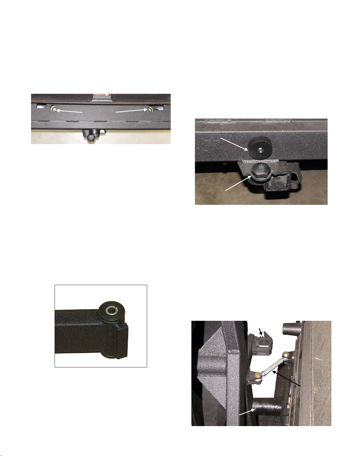
16) Insert the supplied D washers under the bumper
crossmember brackets and on top of the crush
sleeves. See illus 5.
Illus 5
NOTE: Crush sleeve and D washer installation is not
required if your vehicle has an installed RS6509B
suspension system.
17) Attach bumper to crossmember with two M12-1.75 x
100mm bolts, two M12-1.75 stover nuts and 4 washers
from kit 860662. Attach bumper to the frame rails with
the original bolts. Tighten all nuts and bolts to 55 ft.
lbs.
18) Press bushings into tire carrier 176664B with a small
amount of lithium grease. Apply lithium grease to the
pivot sleeve 420091 and inside of the bushings. Press
sleeve into bushings. If there is not a press available, a
bench vise or large C-clamp can be used to press the
bushings and sleeve in. See Illus 6.
CAUTION: Do not use metal hammer to install sleeve!.
Illus 6
19) Attach the tire carrier assembly to mount of bumper
176663B with the supplied ½”-13 x 5.5 bolt, two ½”
USS washers and one ½”-13 stover nut. Tighten nut
and bolt to 65 ft. lbs.
20) Attach lower bump stop support 176669 to bumper
bracket using supplied hardware and spacer 176674.
See illus 7.
21) Attach middle bump stop support 176668 to bumper
tube using supplied self drilling screw and spacer
176676. Bump stop should be in middle of bumper
cross tube and about ½” - .1” to the right of the lower
bump stop. Check that middle bump stop hits the
center of the tire carrier assembly’s vertical tube before
attaching. See illus 7.
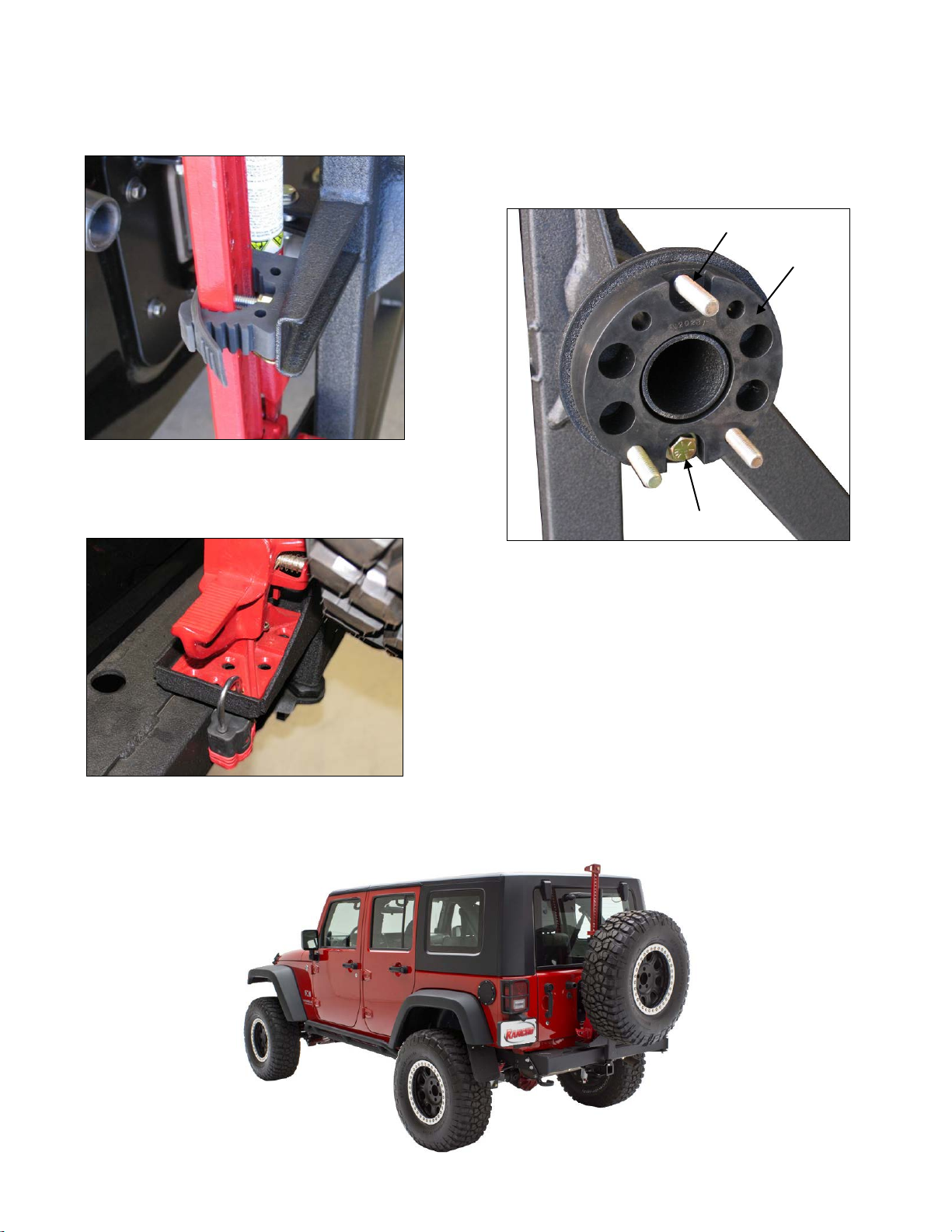
Illus 7
22) Close rear door and tire carrier assembly. Attach free
rod end to tire carrier assembly using supplied 3/8”
hardware.
23) Tighten turnbuckle until tire carrier assembly contacts
top and middle support bump stops. Hold turnbuckle
and tighten jam nuts. Door should close with a slight
resistance from the bump stops. Adjust turnbuckle as
needed. See illus 8
24) To install Hi-Lift Jack, drill out hole in quick fist with a
7/16” bit. Loosely attach quick fist rubber clamps to
tire carrier assembly brackets using supplied 3/8”
hardware. See illus 8.
Illus 8
D washers.
Mark and drill holes
Lower Bump Stop 176669
& Spacer 176675
Middle Bump Stop 176668
& Spacer 176676
Quickfist
Turnbuckle
Top Bump Stop
176667

25) Set jack in tray and slide Quick fist mounting bolts
through holes in jack. Tighten Quick Fist mounting
hardware. See illus 9.
Illus 9
26) A padlock may be used to lock jack to tray. Some jacks
may need hole enlarged to accommodate padlock.
See illus 10.
Illus 10
27) This kit contains hardware to fit OE wheels and
aftermarket wheels. OE lug nuts can beused to secure
wheel to tire carrier.
28) For OE wheel mount: Insert three ½”-20 x 3.0 bolts in
mount plate with provided wheel spacer 176547.
Secure wheel spacer to tire carrier with one ½”-20 x
1.75 bolt as shown in illus 11.
Illus 11
29) For aftermarket wheel with 4.5” backspacing, install
three ½”-20 x 1.75 bolts in mount plate. Secure wheel
to tire carrier with OE lug nuts
NOTE: Tire should fit securely against the frame of the tire
carrier to reduce vibrations and movement. Some unique
combinations of wheel and tires may need to modify spacer
to fit securely against tire carrier frame.
CAUTION: Do not install a spare tire and wheel weighing
more than 100 lbs. Do not use wheel spacer on drive
wheel, use as a spare tire spacer only.
Check clearances by slowly opening the tire carrier and
making sure that the jack or tire does not contact the body
of the vehicle.
½”-20 x 3.0 bolt
½”-20 x 1.75 bolt
176547
Table of contents
Other RANCHO Automobile Accessories manuals
Popular Automobile Accessories manuals by other brands

Cruz
Cruz N Series Assembly instructions

iKeyless
iKeyless SolidKeysUSA FOBIK 300-0388 Pairing Instructions

Soundoff Signal
Soundoff Signal GHOST EGHST4 B Series quick start guide

Metra Electronics
Metra Electronics 99-7390B installation instructions

Metra Electronics
Metra Electronics Axxess CLASSII-100 installation instructions

Thule
Thule Ocean 80 Fitting instructions