RANCHO RS66402B User manual

89402 Rev A
INSTALLATION INSTRUCTIONS
For Rancho Suspension Systems:
RS66402B —
4½” Lift
2017-2013 Ram 1500 4WD
DOES NOT FIT VEHICLES EQUIPPED WITH AIR RIDE.
WARNING
Carefully read, understand and follow the instructions provided in this manual, and keep it in a safe place for future reference. If you have any doubt
whatsoever regarding the installation or maintenance of your Rancho suspension system, please see your retailer for assistance or advice. Failure to
follow the warnings and instructions provided herein can result in the failure of the suspension system, or can cause you to lose control of your vehicle,
resulting in an accident, severe personal injury or death.
These instructions should remain in the vehicle glove box for future reference.
895402 Rev A
Fits
Fits OE 17” and up rims
ONLY WITH OE TIRES

2
WARNING: READ ALL INSTRUCTIONS THOROUGHLY FROM
START TO FINISH BEFORE BEGINNING INSTALLATION. Failure to
follow the warnings and instructions provided herein can result in an
accident, severe personal injury or death.
PRELIMINARY
This manual presumes that all persons installing this suspension
s stem have a high level of mechanical training and experience, and
have available to them all necessar tools and safet equipment. This
manual is not and should not be construed as an exhaustive list of all
required safet measures. Personnel should rel primaril on their
training and experience, as well as on their own common sense.
This Manual is to be read as a supplement to, and must not be
construed as a substitute for, the owner’s manual and/or shop
manual that originall accompanied the vehicle. Refer to such use,
operation, maintenance and safet manuals as necessar , and
especiall after installation is complete, to insure proper vehicle
operation.
The following terminolog has been used in this Manual:
ACCIDENT: An event which could cause personal injur or death to
an one installing or using the suspension s stem, as well
as to passengers and b standers, or otherwise ma result
in propert damage.
PRE-INSTALLATION WARNINGS and INSTRUCTIONS
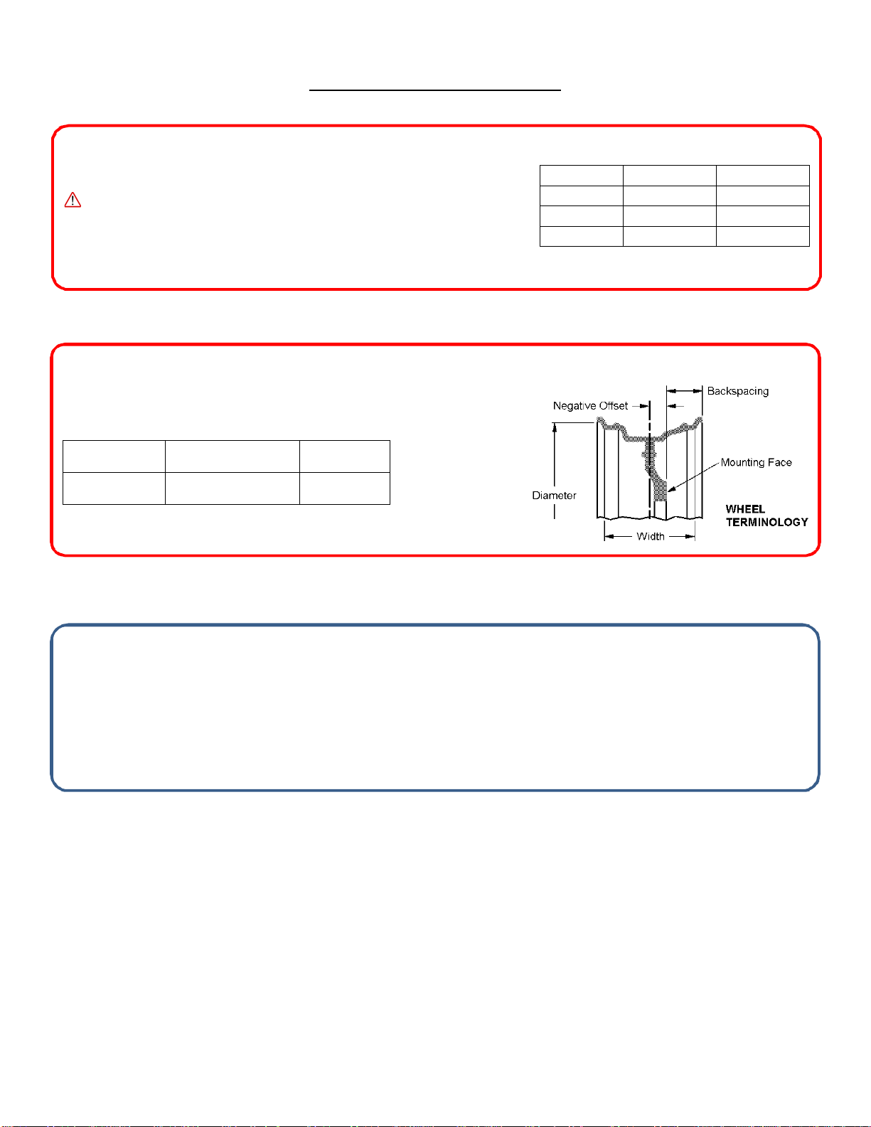
WARNING: Only the following rim/tire sizes may be used with this
suspension system: 295/60R20 tire, 20x9-in 0 offset wheel.
Use of any other rim/tire combination increases the risk of a roll-over
and/or accident, resulting in severe personal injury or death.
WARNING: This suspension system will enhance the off-road
performance of your vehicle. It will handle differently; both on and off-
road, from a factory equipped passenger car or truck. Failure to drive
this vehicle safely may result in serious injury or death to the driver and
passengers. ALWAYS WEAR your seat belts, REDUCE your speed, and
AVOID sharp turns and other abrupt maneuvers
1)
Service and repair tasks require specialized knowledge, training,
tools, and experience. General mechanical aptitude ma not be
sufficient to properl install this suspension s stem. If ou have an
doubt whatsoever regarding our abilit to properl install the
suspension s stem, please consult a qualified mechanic.
2)
Your brake lines and fuel lines should remain undisturbed during
and after installation. If ou think ou need to modif these
components in an wa , ou are mistaken. You are installing the lift
improperl and will be creating a significant risk of an accident. In case
of an doubt, consult a qualified mechanic.
3)
If an component does not fit properl , something is wrong. You
are installing the lift kit improperl and will be creating a significant
risk of an accident. Never modif an component of the vehicle or
suspension s stem, except as instructed herein. Do not continue with
installation until ou have identified the problem.
4)
Several of the procedures described herein require at least two (2)
persons to safel complete the task. If ou have an doubt about our
abilit to complete an operation b ourself, alwa s ask for help
from a qualified assistant.
5)
Before starting an operation, confirm that all personal safet
devices and safet equipment are in proper condition and position.
6)
Give our work undivided attention. Looking around, carr ing on a
conversation and "horse-pla " are careless acts that can result in an
error in installation and/or serious injur .
7)
Install onl tires approved b the United States Department of
Transportation (“DOT approved”). Make sure the rim and tire size are
properl matched.
8)
If an components of the vehicle or suspension s stem are
damaged in an wa during installation, immediatel replace the
component.
9)
During installation, carefull inspect all parts of the vehicle and
replace an thing that is worn or damaged.
10)
Nip points present the risk of the catching, lacerating, crushing
and/or amputating fingers, hands, limbs and other bod parts during
operations. Alwa s keep clear. Wear protective gloves.
11)
Oil and h draulic fluids are poisonous, dangerous to health and
are known to the State of California to cause cancer, birth defects or
other reproductive harm. Do not inhale vapors or swallow. Do not
allow contact with the e es or skin. Should an oil or fluids be
swallowed or inhaled or come into contact with the e es,
immediatel follow the safet precautions on the label or call a poison
control center immediatel . Should an of the oil or fluids contact
our skin, immediatel wash thoroughl .
12)
Never install the suspension s stem if ou are under the effects of
alcohol, medications and/or drugs. If ou are taking prescription or
over the counter medication, ou must consult a medical professional
regarding an side effects of the medication that could hinder our
abilit to work safel .
AFTER INSTALLATION WARNINGS AND INSTRUCTIONS
13)
After installation is complete, drive the vehicle slowl in an area
free from heav traffic for at least three (3) miles. Likewise, before
traveling on an highwa s or at a high rate of speed, drive the vehicle
for ten (10) miles on side roads at moderate speed. If ou hear an
strange noise or feel unusual vibration, if a component of the
suspension s stem is not operating properl , or if an warning lights
illuminate or buzzers sound, stop the vehicle immediatel . Identif
the cause and take an necessar remedial action.
14)
Confirm that all components of the vehicle, including all lights
(headlights, turn signals, brake lights, etc.), linkages (accelerator,
etc.), electrical switches and controls (windshield wipers and
defoggers, etc.), and other warning devices (low tire pressure
monitoring s stems) are full operational.
15)
Your headlights will need to be readjusted before the vehicle is
used on the roads. Consult the vehicle owners’ manual.
16)
The speedometer and odometer will need to be recalibrated after
installation. See our dealer.
17)
Confirm proper rear view and side view while seated in the driver
seat. Install supplemental mirrors as necessar .
18)
Your original low tire pressure monitoring s stem ma be re-
installed in our new wheels. However, if ou choose to purchase a
new s stem, see our dealer to have them properl calibrated. Proper
tire pressure is critical to safe operation of the vehicle.
OPERATION
19)
Because it has been modified, the vehicle will not handle, turn,
accelerate or stop in the same manner as an unmodified vehicle. In
addition, the crash protection s stems designed in the vehicle ma
operate differentl from an unmodified vehicle. For example, turning
and evasive maneuvers must be executed at a slower rate of speed.
Further, there is a greater risk that the vehicle could roll over. These
differences could result in an increased possibilit of an accident,
personal injur or death. Learn the vehicle’s operations and handling
characterizes and drive accordantl .

3
IMPORTANT NOTES
A. Before installing this s stem, have the vehicle’s alignment and
frame checked b a certified technician. The alignment must
be within factor specifications and the frame of the vehicle
must be sound (no cracks, damage or corrosion).
Have all suspension, steering and driveline components
inspected and replaced if worn or damaged
B. The components of Rancho’s suspension s stem are designed
as a single integrated s stem. To avoid compromises in terms
of safet , performance, durabilit or function, do not install a
bod lift kit with Rancho’s suspension s stem or interchange
parts from this s stem with components from another
manufacturer. Use of other components will result in the
forfeiture of an t pe of warrant on the vehicle/suspension
s stem.
C. Some components required for the installation of this kit ma
need to be purchased separatel . See “SPECIFICATIONS &
REQUIREMENTS” on next page of this manual.
D. Compare the contents of this s stem with the parts list in these
instructions. If an parts are missing, contact the Rancho
Technical Department at 1-734-384-7804.
E. Do not powder-coat or plate an of the components in this
s stem. To change the appearance of components,
automotive paint can be applied over the original coating.
F. Each hardware kit in this s stem contains fasteners of high
strength and specific size. Do not mix hardware kits or
substitute a fastener of lesser strength. See bolt identification
table at end of instruction.
G. Install all nuts and bolts with a flat washer. When both SAE
(small OD) and USS (large OD) washers are used in a fastener
assembl , place the USS washer against the slotted hole and
the SAE washer against the round hole.
H. Appl a drop of thread locking compound to all bolts during
installation. CAUTION: Thread locking compound ma
irritate sensitive skin. Read warning label on container before
use.
I. Unless otherwise specified, tighten all nuts and bolts to the
standard torque specifications shown in the table at end of
instruction. USE A TORQUE WRENCH for accurate
measurements.
J. Do not weld an thing to these components, and do not weld
an of these components to the vehicle unless specificall
stated in the instructions
K. It is extremel important to replace coil springs, axle flanges,
and drive shaft/pinion relationships as original. Be sure to
mark left/right, front/rear, and indexing of mating parts
before disassembl . A paint marker or light colored nail polish
is hand for this.
L. Suspension components that use rubber or urethane bushings
should be tightened with the vehicle at normal ride height
unless otherwise specified. This will prevent premature failure
of the bushing and maintain ride comfort.
M. Some of the service procedures require the use of special tools
designed for specific procedures. If ou do not know how to
safel use an of these tools, or do not have them, stop the
project and consult a qualified mechanic. See “Tools and
Supplies” on next page of this manual
N. The required installation time for this s stem is approximatel
5 to 6 hours for two people. Check off the box () at the
beginning of each step when ou finish it. Then when ou stop
during the installation, it will be easier to find where ou need
to continue from.
O. Important information for the end user is contained in the
consumer/installer information pack. If ou are installing this
s stem for someone else, place the information pack on the
driver’s seat. Please include the installation instructions when
ou finish.
P. The lifespan of Rancho products depends on man factors.
Improper use, abuse or harsh use in general ma compromise
the integrit of the suspension s stem and significantl reduce
its lifespan. The suspension s stem is also subject to wear over
time. Have the suspension s stem regularl inspected and
maintained b qualified mechanics. If the inspection reveals
an damage or excessive wear, no matter how slight,
immediatel replace or repair the component. The suspension
s stem must be regularl maintained in order to optimize its
safe and efficient use. The more severe the conditions under
which the suspension s stem is operated, the more often it
must be inspected and maintained.
Q. If an component breaks or bends, contact our local Rancho
dealer or Rancho for replacement parts or, contact the Rancho
Technical Department at 1-734-384-7804.
Thank ou for purchasing the best suspension s stem available. For the best installed s stem, follow these instructions. If ou
do not have the tools or are unsure of our abilities, have this s stem installed b a certified technician. RANCHO IS NOT
RESPONSIBLE FOR DAMAGE OR FAILURE RESULTING FROM AN IMPROPER INSTALLATION
The driver of this suspension system recognizes and agrees that there are risks inherent in driving a vehicle with a lifted suspension system, including but
not limited to the risk that you could be involved in an accident that would not occur in an unmodified vehicle. By his/her purchase and use of this
suspension system, the user expressly, voluntarily and knowingly accepts and assumes these risks, and agrees to hold Tenneco, Inc. and its related
companies harmless to the fullest extent permitted by law against any resulting damages.

4
SPECIFICATIONS & REQUIREMENTS
Shock Absorbers
New Rancho shock absorbers must be used with this kit, and must be purchased
separatel
WARNING Use of the wrong shock absorbers cancause damage
to vehicle without the damage being visible to you, resulting in loss of
vehicle control and an accident
Required Rancho Shock Absorbers
Front
Rear
RS7000MT
RS7810 RS7369
RS5000X
RS55810 RS55369
RS5000
RS5810 RS5369
Wheels and Tires
Tools and Supplies
(BECAUSE OF VEHICLE VARIATIONS, THIS MAY NOT BEA COMPLETE LIST)
Dodge Service Manual
Coil Spring Compressor
Ball Joint Removing Tools 8677 & 9360
(Miller or Mopar)
Drill motor
Reciprocating saw
Assorted Drills: 1/8" through 1/2"
Torque Wrench (250 FT-LB capacit )
1/2” Drive Ratchet and Sockets
Assorted Socket Extensions
(at least 18” combined)
21 mm Open End Crowfoot Wrench
(Snap-on SCOM21 or equivalent)
Assorted Combination Wrenches
Heav Dut Jack Stands
Wheel Chocks (wooden blocks)
H draulic Floor Jack
Center punch
File
Hammer
Wire Brush (to clean bracket mounting
surfaces)
Dot 3 Brake Fluid
Black Enamel Paint
Silicone Spra Lubricant
Tape Measure
Safety Glasses--
Wear safet glasses at all times
This suspension s stem was developed using the following tire & wheel combination:
Tire: LT295/60R20
Wheel: 90 x 9 x 0 Offset (5.0” Backspacing)
Before installing an other combination, consult our local tire and wheel specialist.
Compatible With
OE Wheels
Development Tire Size
(Actual)
Wheel Size
(Backspacing)
Yes
–
17” and up
with OE tires
1
LT295/60R20
(34”x11.7”)
20
x9
(5.0”)
1
OE wheels compatible with stock size tires onl .

5
Parts List
ITEM
PART # DESCRIPTION
QTY
RS66402B
-
1
Box 1
1
1
RS176588B
Sub
F
rame
1
RS66402B
-
2
Box 2
1
2
RS176230
Knuckle, Left
1
RS66402B
-
Box
1
3
RS176231
Knuckle, Right
1
RS66402B
-
4
Box 4
1
RS860562
Sub Ass
-
Subframe
1
RS7861
Washer, M16
8
RS770030
Nut, M16
-
2.00 Top Lock
4
136763624
Strap
-
Black
4
RS42702
.5 cc Thread Lock
2
4
RS176421
Subframe Washer
2
RS770040
HHCS, M16
-
2.0X140
4
RS770151
Washer, 5
/8 USS
6
5
RS602614
Outer Tie Rod End
2
6
RS602641
Inner
Tie Rod
2
RS860460
Sub Ass , Ram Hub Spacer
1
7
RS176232
Hub Spacer
2
8
RS176841
Right Diff Drop
–
Forward Bracket
1
9
RS176834
Right Diff Drop
–
Rear Bracket
1
10
RS176837
Right Drop
Diff Spacer
1
1
1
RS176651
Driver Side
Diff Drop
–
Right Bracket
1
1
2
RS176240
Driver Side
Diff Drop
–
Left Bracket
1
RS860820
Sub Ass ,
Diff Drop Brackets
2
RS770072
HHCS, M12
-
1.75X60
2
RS7915
Washer, M12
4
RS7911
Nut, M12
-
1.7
5 Top Lock
2
1
3
RS176653
Aft Diff Drop
Bracket
1
RS860707
Sub Ass
-
Aft Diff Drop
Bracket
1
RS770107
HHCS, M12
-
1.75X35
6
RS7915
Washer, M12
6
ITEM
PART # DESCRIPTION
QTY
1
4
RS176835
Front Drive Shaft Spacer
1
RS860822
Sub Ass , Dri
ve Shaft Spacer
1
RS770108
HHCS, M12
-
1.75X40
4
RS7915
Washer, M12
4
1
5
RS176419
Front Swa Bar
End L
ink
Extension
2
1
6
RS170108
Brake Line, Front Left
1
1
7
RS170109
Brake Line, Front Ram
1
RS860730
Sub Ass ,
Rear Brake Line
1
18
RS
176698
Rear Brake Line/Swa Bar Drop
2
RS770127
HHCS, M
8
-
1.25X20
2
RS603112
Nut, M8
-
1.25 N lock
2
RS770128
Washer, M8
4
136763624
Strap
-
Black
2
RS770247
HHCS M12
-
1.75X25
2
RS7807
Nut, M12Mm
-
1.75 N lo
ck
2
RS7915
Washer, M12
4
1
9
RS176589
Rear Bump
S
top Spacer
2
RS860670
Sub Ass ,
Rear Bump
S
top Spacer
1
RS770106
HHCS, M12
-
1.75X30
2
RS7807
Nut, M12
-
1.75 N lock
2
RS7915
Washer, M12
4
RS860671
Sub Ass , Rear Coil
2
20
RS821B
Rear Coil Spring
1
RS94180
Information Pack
1
RS89402
Instructions
1
RS94177
Rollover Warning L
abel
1
RS94119
Consumer/Warrant Information
1
RS780281
6" Rancho Decal
1
R-RM0082-1112
Warrant Tag
1
1
2
3
5 5
6
77
11
12
8
9
10
13
14
15
15
16
17
18
18
19
19
20
20
4
4

6
FRONT SUSPENSION
V
EHICLE
P
REPARATION
1)
Park the vehicle on a level surface. Set the parking
brake and chock rear wheels. Measure and record the
distance from the center of each wheel to the top of the
fender opening. See Illustration 1.
Illustration 1
2)
Loosen the front lug and hub nuts before raising the
vehicle.
3)
Raise the front of the vehicle and support the frame
with jack stands. Remove the front wheels and set them
aside.
S
KID
P
LATE
R
EMOVAL
(
IF APPLICABLE
)
1)
Remove the bolts holding the differential skid plate to
the front cross member. See Illustration 2. Slide the skid
plate back and remove.
Illustration 2
B
RAKE
H
OSE
R
EPLACEMENT
NOTE: If the master cylinder becomes empty, then the entire
brake system must be bled. Follow manufacturer’s
recommendations for bleeding the entire system.
1)
Separate the passenger side brake line from the brake
hose at the frame rail. Plug line to prevent brake fluid
seepage.
2)
Remove the bolt holding the brake hose to the frame.
See Illustration 3.
Illustration 3
3)
Remove the brake hose banjo bolt at the caliper.
Remove brake hose.
4)
Attach right brake hose RS170109 to the caliper with
new washers and the original banjo bolt. See Illustration 4.
Tighten the bolt to 20 ft. lbs.
Illustration 4
5)
Attach brake hose RS170109 to the brake line and
frame. Tighten the original frame bolt to 7.5 ft. lbs. and the
brake line fitting to 14 ft. lbs.
6)
Repeat steps 1 through 6 to install left brake hose
RS170108 on the driver side.
7)
Bleed the front brakes as follows:
Fill master cylinder reservoir with approved brake fluid.
Attach a clear hose to bleeder valve of right front caliper.
Immerse other end of hose into glass container partially filled
with brake fluid.
Open bleeder valve, and then have a helper press down on
the brake pedal.
Close bleeder valve and repeat process until fluid is clear
and free of bubbles.
Repeat steps for left front caliper.

7
S
TEERING
K
NUCKLE
R
EMOVAL
1)
Remove the brake caliper and its mounting bracket as
an assembl . Hang the caliper assembl with wire or a tie
wrap.
WARNING: Do not allow the caliper to hang by the brake hose. You
could damage the hose, without this damage being visible to you,
resulting in sudden and unexpected brake failure and an accident.
2)
Mark the brake rotor left or right. Remove the brake
rotor. If applicable, disconnect the ABS speed sensor from
the hub b removing the allen screw and pulling sensor out
of hub.
3)
Remove the axle shaft hub nut.
WARNING: Do not hammer the ball studs to separate them from
components. You could damage the ball studs, without this damage
being visible to you, resulting in sudden and unexpected failure of the
ball studs and an accident.
4)
Loosen the tie rod end jam nut. Loosen the outer tie
rod stud nut. Separate the outer tie rod end from the
steering knuckle with removing tool 9360. Remove the nut
and outer tie rod stud from knuckle. See Illustration 5.
Illustration 5
5)
Loosen the nut at the upper ball joint. Using removing
tool 9360, separate the ball joint from the steering knuckle.
Pr down upper control arm and remove nut and upper ball
joint from steering knuckle. See Illustration 6.
Illustration 6
6)
Loosen the nut at the lower ball joint. Using removing
tool 8677, separate the ball joint from the steering knuckle.
See Illustration 7.
Illustration 7
7)
Remove nut from lower ball joint and remove the
steering knuckle. Hang the half shaft with wire or a tie
wrap.
8)
Repeat steps 1 through 7 for other side.
C
OIL
-O
VER
&
L
OWER
C
ONTROL
A
RM
R
EMOVAL
1)
Remove the upper nut from both end links. Remove
the upper retainers and grommets. Separate the swa bar
from the end links. See Illustration 8.
Illustration 8
2)
Mark the lower control arm pivot bolts for installation
reference. Loosen, but DO NOT REMOVE the lower control
arm pivot bolts. See Illustration 9 .
Illustration 9

8
3)
Support the lower control arm with a jack.
4)
Remove the three upper coil-over nuts. See
Illustration 10. Do not remove the center rod nut.
Illustration 10
5)
Remove the lower coil-over nut and bolt. See
Illustration 9. Lower jack and remove the coil-over
assembl .
6)
Remove lower control arm pivot bolts and lower
control arm.
7)
Repeat steps 2 through 6 for the other side.
I
NNER
&
O
UTER
T
IE
R
OD
R
EPLACEMENT
1)
Remove clamps from rack and pinion boot. See
Illustration 11. Slide boot to expose rack and inner tie rod.
Illustration 11
NOTE: Keep rack clean while exposed.
2)
Unthread inner tie rod from rack. Remove the tie rod
assembl .
3)
Remove outer tie rod end and jam nut. Remove OE
clamp and boot.
4)
Install OE boot, OE clamp and new jam nut on inner
tie rod RS602641. Install jam nut to end of threads. See
Illustration 12
5)
Appl a small amount of thread lock to inner tie rod
RS602641. Attach new tie rod assembl to rack. Tighten
inner tie rod to 125 ft. lbs. Do not over tighten.
Illustration 12
6)
Install boot in original location on rack and inner tie
rod. Secure boot to rack with a tie wrap from hardware kit
RS860562. Secure boot to inner tie rod with the OE clamp.
7)
Attach outer tie rod end RS602614 to tie rod
RS602641. As reference leave a .45 gap between jam nut
and tie rod end.
8)
Repeat steps 1 through 7 for the other side.
F
RONT
D
IFFERENTIAL
D
ROP
B
RACKET
I
NSTALLATION
1)
Remove the bolts attaching the cross member to the
rear frame brackets of the lower control arms. See
Illustration 13. Remove the cross member.
Illustration 13
2)
Referance mark and disconect the front driveshaft at
the pinion flange. See Illustration 13.
Hang the driveshaft to prevent damage to CV boot at
transfer case end of driveshaft.
3)
Disconnect the wire harness plug from the front
differential. See Illustration 15.
4)
Disconnect an wires or hoses attaching the front
differential and axle to vehicle.
5)
Carefull remove ties holding axle half shafts.
CAUTION: Take care not to damage CV boot.
RS602641
RS602614
Cross Member
Mark and Remove

9
Illustration 14
Illustration 15
WARNING: DO NOT allow differential to be supported only by the
right/passenger side axle tube mount. DO NOT allow any twisting or side
loading of the right/passenger side axle tube mount. Damage to the
differential axle tube can result without the damage being visible to you,
resulting in loss of vehicle control and an accident.
6)
Support the front differential assembl with a jack.
7)
Remove the differential housing aft mounting bolts.
See Illustration 14.
8)
Remove the passenger side axle tube mounting bolts
and axle dampener (if equipped). See Illustration 15.
9)
Remove the differential housing driver side forward
mount bolts. Carefull lower the differential assembl . See
Illustration 16.
CAUTION: Take care not to damage CV boot.
10)
To provide clearance for the differential, cut off the
driver side cross member frame bracket at the center of the
outer cross member mounting hole. See Illustration 17. File
sharp edges and paint exposed metal.
WARNING: Do not use a flame cutter or torch to remove bracket.
You could warp, weaken or damage the bracket without the damage
being visible to you, resulting in loss of vehicle control and an accident.
WARNING: Failure to follow differential drop bracket installation and
torque sequence can result in damage to the differential axle tube!
11)
Loosel install aft diff drop bracket RS176653 on
differential housing using M12-1.75X35 bolts from kit
RS860707. See Illustration 18.
12)
Using the OE hardware, loosel attach driver side
forward drop brackets RS176240 (left half) and RS176651
(right half) to the OE frame mount. See Illustration 19 and
Illustration 20.
13)
With the help of an assistant raise the differential up
and loosel attach differential’s driver side forward mount
to differential drop brackets RS176240 and RS176651 using
hardware for kit RS86020. See Illustration 20 and
Illustration 21.
Illustration 16
Illustration 17
Illustration 18
RS176653
Hardware from RS860707
Cut Line
Cut Line Remove
Dampener
Plug
Mounting Bolts
Aft Mount
Forward Mount
Forward Mount

10
14)
Using the remaining hardware from kit RS860707,
loosel attach aft drop bracket RS176653 to the aft OE
frame mount. See Illustration 21.
15)
Using OE hardware, loosel and the axle tube drop
brackets RS176841 (forward half) and RS17634 (rear half)
to the passenger side OE frame mount along with spacer
RS176422 OR the OE dampener mount (if equipped). See
Illustration 22 and Illustration 23.
The wider end of each bracket with the notch is attached
to the top.
16)
Using 12mm hardware from kit RS860820, loosel
attach differential passenger side axle tube mount drop
brackets RS176654 and RS176239. See Illustration 22 and
Illustration 23.
DO NOT TIGHTEN! BRACKETS MUST BE LOOSE!
TIGHTEN BRACKETS IN THE FOLLOWING ORDER:
17)
FIRST - Snug the six differential aft mounting bolts
until the aft drop bracket RS176653 sits flush with frame
mount and differential. See Illustration 21.
18)
SECOND - Snug the four differential housing driver
side forward mount bolts until the drop brackets sit flush
with the frame mount and differential. See Illustration 20
and Illustration 21.
19)
THIRD - Tighten the differential housing aft mounting
bolts to 70 ft. lbs.
20)
FOURTH - Tighten the differential housing driver side
forward mounting bolts to 70 ft. lbs.
21)
FIFTH – Slowl snug the passenger side axle tube
mounting bolts starting with the upper bolts, while
confirming the drop brackets are installed correctl . See
Illustration 22 and Illustration 23.
The passenger side brackets must align properly with
the mounts. If there is more than 1/16” (.063”) gap in any
location, shimming will be required to prevent excessive side
loads being applied to the differential axle tube.
If the brackets and mount are not parallel to each other,
loosen and re-torque the differential housing rear mounting
bolts.
WARNING: Do not tighten the passenger axle tube mounting brackets if
step 21 cannot be successfully completed!
22)
SIXTH - When the right/passenger axle tube
mounting and spacer brackets are installed and aligned
properl , tighten mounting bolts to 70 ft. lbs.
23)
Hang the half shaft with wire or a tie wrap.
Illustration 19
Illustration 20
Illustration 21
Illustration 22
RS176841
RS176834
Spacer RS176837
RS176651
RS176240
FRONT
RS176240 RS176651
Differential
OE Hardware
Hardware from RS860820
Frame Mount
RS176653
FRONT
Aft Frame Mount
Forward Frame Mount
Frame Mount

11
Illustration 23
D
RIVESHAFT
S
PACER
I
NSTALLATION
1)
Align marks on front driveshaft and pinion flange.
2)
Install driveshaft spacer RS176835 between pinion
flange and driveshaft using hardware from kit RS860822
and threadlock. The raised surface of the spacer fits into the
recess of the flange. Torque to 55 ft. lbs. See Illustration 24.
Illustration 24
S
UB
-
FRAME
I
NSTALLATION
1)
With an assistant’s help, raise sub-frame RS176588B
up into the lower control arm frame brackets. See
Illustration 25.
Illustration 25
2)
Attach the sub-frame with the hardware from kit
RS860562. Install a small washer and centering plate
RS176421 on each rear bolt. Insert all bolts from front to
back. See Illustration 26.
Illustration 26
3)
Tighten the sub-frame nuts and bolts to 155 ft. lbs.
L
OWER
C
ONTROL
A
RM
&
S
HOCK
A
BSORBER
I
NSTALLATION
1)
Insert the left lower control arm into the sub-frame
pockets on the driver side. Loosel attach the control arm
with the original hardware. Align cam bolts if so equipped.
NOTE: Do not tighten pivot bolts until vehicle is at normal
ride height.
2)
Insert the right lower control arm into the sub-frame
pockets on the passenger side. Loosel attach the control
arm with the original hardware. See Illustration 27.
Illustration 27
3)
Install the driver side coil over assembl into a qualit
spring compressor. Mark coil, shock and upper mount for
installation reference. Carefull compress the coil spring.
4)
Hold the shock shaft and remove the upper shock nut.
Remove the shock.
5)
Assemble lower spring seat and OE jounce bumper on
new Rancho shock absorber according to instructions
supplied with shock absorber.
RS176588B
RS176588B
RS176841
RS176834
OE Dampener Mount
RS176835
Frame Mount

12
7)
Insert shock assembl into coil spring. Install OE
isolator and mounting plate. See Illustration 28. Align
reference marks and install upper nut. Tighten nut to 45 ft.
lbs.
Illustration 28
8)
Carefull release tension on coil spring. Remove coil
over from spring compressor.
9)
Repeat steps 3 through 8 for the passenger side.
10)
Insert the top of the right coil over assembl into the
passenger side frame bracket. Loosel attach coil over to
bracket with the original nuts.
11)
Loosel attach the bottom of the coil over to the
lower control arm with the original hardware. Insert bolt
from back to front, but do not tighten.
12)
Torque upper shock mounting nuts to 45 ft. lbs.
S
TEERING
K
NUCKLE
I
NSTALLATION
1)
Remove the three hub mounting bolts from the
passenger side steering knuckle. Separate the hub, dust
shield and ABS clip (if applicable), from the knuckle. See
Illustration 29.
Illustration 29
2)
Attach dust shield, hub and ABS line (use tie-wrap) to
right steering knuckle RS176231. Tighten hub bolts to
120 ft. lbs.
NOTE: If equipped with ABS brakes, position the speed
sensor opening on the hub toward the front of the vehicle.
3)
Install axle hub spacer RS176232 on the passenger
side axle shaft. See Illustration 30.
Illustration 30
4)
Support the lower control arm with a jack. Insert axle
shaft through hub and install steering knuckle RS176231
onto the lower ball joint. Install lower ball joint nut.
CAUTION: The ball joint studs must be free from residue
(nylon) prior to installing new knuckle.
Illustration 31
5)
Insert the upper ball joint into the knuckle. Install
upper ball joint nut. See Illustration 31.
6)
Tighten the upper ball joint nut to 75 ft. lbs. Tighten
the lower ball joint nut to 110 ft. lbs.
7)
Install the axle shaft hub nut and tighten to 185 ft. lbs.
8)
Attach outer tie rod end to steering knuckle with the
original nut. Tighten ball stud nut to 50 ft. lbs. Tighten the
jam nut to 94 ft. lbs.
9)
Repeat steps 1 through 10 to install the left coil over
and steering knuckle RS176230 on the driver side.
10)
Install the brake rotor. Attach the front caliper to
the steering knuckle with the original mounting bolts.
Tighten the caliper mounting bolts to 130 ft. lbs.
RS5810
OE Coil

13
E
ND
L
INK
E
XTENDER
I
NSTALLATION
1)
Appl thread lock to the original end link. Attach end
link extender RS176419 to end link. See Illustration 32.
Tighten extender securel .
2)
Attach the end link assembl to the swa bar with the
original retainers, bushings and nut. Tighten nut to 20 ft. lbs.
3)
Repeat steps 1 and 2 for the other side.
4)
Install front wheels and lower vehicle to ground.
Tighten the lug nuts to 130 ft. lbs.
5)
Align reference marks and tighten the lower control
arm pivot bolts to 155 ft. lbs. Tighten the lower shock
mounting bolts to 155 ft. lbs.
Illustration 32
REAR SUSPENSION
S
HOCK
A
BSORBER
&
C
OIL
S
PRING
R
EMOVAL
1)
Chock front wheels.
2)
Remove the bolt and nut holding the track bar to the
rear axle.
3)
Remove the bolt and nut holding the swa bar end
links to the frame.
4)
Raise the rear of the vehicle and support the frame
with jack stands. Remove rear wheels.
5)
Support the rear axle assembl with a floor jack.
6)
Remove the upper and lower shock mounting bolts.
Remove shock absorber.
NOTE: It may be necessary to remove fender well liner
screws and pull liner out to assess and remove upper shock
mounting bolt. Use a 21mm crowfoot wrenchand extensions
to hold nut from spinning.
7)
Remove brake line wire hanger from frame, and ABS
cable from holders.
8)
Repeat step 6 and 7 for other side.
9)
Carefull lower the rear axle. Do not allow the axle to
hang b an hoses or ABS cables.
WARNING: Do not allow the axle to hang by any hoses or ABS
cables. You could damage the hoses or ABS cables, without this
damage being visible to you, resulting in sudden and unexpected failure
of a hose or ABS system, and an accident.
10)
Remove both coil springs and insulators from vehicle.
B
UMP
S
TOP
S
PACER
I
NSTALLATION
1)
On driver’s side, place bump stop spacer RS176589 on
top of lower link axle pad. Align the hole in the spacer with
the existing hole on the axle pad.
2)
Attach bump stop spacer to axle pad with 12mm
hardware from kit RS860670. Tighten to 55 ft. lbs. See
Illustration 33.
Illustration 33
3)
Repeat steps 1 & 2 for passenger side.
C
OIL
S
PRING AND
S
HOCK
A
BSORBER
I
NSTALLATION
1)
On driver side place coil spring RS821B onto the rear
axle pigtail end down. Attach original insulator to top of coil,
then raise the axle guiding the springs into the frame
pockets. See Illustration 34.

14
Illustration 34
2)
Attach new Rancho shock absorbers to the upper and
lower mounts. Torque to 100 ft. lbs.
3)
Repeat steps 4 and 5 for passenger side.
B
RAKE
L
INE
/
S
WAY
B
AR
B
RACKET
I
NSTALLATION
1)
Install brake line/swa bar drop bracket RS176698 to
frame using OE brake line mounting bolt and M12 hardware
from kit RS860730. Torque OE bolt to 18 ft. lbs. and M12
hardware to 55 ft. lbs.
2)
Attach swa bar end links to drop bracket RS176698
using OE hardware. Torque to 55 ft. lbs
3)
Attach brake-line wire hanger to drop bracket
RS176698 using supplied M8 hardware form kit RS860730.
Torque to 18 ft. lbs.
4)
Reattach ABS cable using supplied tie wraps. See
Illustration 35.
Illustration 35
5)
Install rear wheels and lower vehicle to ground.
Tighten lug nuts to 130 ft. lbs.
6)
Reinsert original track bar bolt into axle bracket.
Tighten to 110 ft. lbs. See Illustration 36.
Illustration 36
FINAL CHECKS & ADJUSTMENTS
1)
Turn the front wheels completel left then right.
Verif adequate tire, wheel, and brake hose clearance.
Inspect steering and suspension for tightness and proper
operation.
2)
With the suspension at maximum extension (full
droop), inspect and rotate all axles and drive shafts. Check
for binding and proper slip oke insertion. The slip oke
should be inserted a minimum of one inch into the transfer
case and/or transmission.
3)
Ensure that the vehicle brake s stem operates
correctl . If new brake hoses were installed, verif that
each hose allows for full suspension movement.
4)
Readjust headlamps.
5)
Have vehicle aligned at a certified alignment facilit .
Recommended Alignment Specifications
Caster (degrees): 3.75°± .75°
Camber (degrees): 0°- .3°
Sum Toe In (degrees): .1°± .1°
Front
OE Hardware
Brake Line Hanger
ABS Cable
End Link RS176698

15
T
RIM
I
NNER
T
IE
R
OD
(
IF REQUIRED
)
NOTE: On some models it may be necessary to shorten the
tie rod to adjust toe to specifications.
1)
Refer to step four of the section “STEERING KNUCKLE
REMOVAL” (page 7) to remove outer tie rod end.
2)
Keep lock nut on inner tie rod and cut 1/4” – 3/8” off
of end of inner tie rod using a cutoff wheel. De-burr after
cutting. See Illustration 37
Illustration 37
3)
Re-attach outer tie rod end RS602614 to tie rod
RS602641. As reference leave a .45 gap between jam nut
and tie rod end. Refer back to Illustration 12.
4)
Attach outer tie rod end to steering knuckle with the
original nut. Tighten ball stud nut to 50 ft. lbs. Tighten the
jam nut to 94 ft. lbs.
F
INAL
M
EASURMENT
1)
Park the vehicle on a level surface Measure and
record the distance from the center of each wheel to the
top of the fender opening. See Illustration 38.
Illustration 38
Please retain this publication for future reference. See Important Note O.

16
Torque Specs
Front Components
Caliper Brake Hose Banjo Bolt 20 ft. lbs
Brake Hose Fitting (at frame) 14 ft. lbs.
Brake Line Frame Clip 7.5 ft. lbs.
Differential Mounts 70 ft. lbs.
Front Driveshaft 55 ft. lbs.
Sub-Frame 155 ft. lbs.
Shock Absorber Rod Nut 45 ft. lbs.
Shock Absorber Upper Mount (to frame) 45 ft. lbs.
Shock Absorber Lower Mount (to control
arm) 155 ft. lbs.
Hub Bolts 120 ft. lbs.
Upper Ball Joint 75 ft. lbs.
Lower Ball Joint 110 ft. lbs.
Outer Tie Rod End (to knuckle) 50 ft. lbs.
Outer Tie Rod End Jam Nut 94 ft. lbs.
Inner Tie Rod (to rack) 125 ft. lbs.
Axle Nut 185 ft. lbs.
Brake Caliper (to knuckle) 130 ft. lbs.
Sway Bar End Link Bushing nut 20 ft. lbs.
Lower Control Arm 155 ft. lbs.
Wheel Lug Nuts 130 ft. lbs.
Rear Components
Bump Stop Spacer RS176589 55 ft. lbs.
Shock Absorber Upper Mount 100 ft. lbs.
Shock Absorber Lower Mount 100 ft. lbs.
Brake Line/Sway Bar bracket RS176698 –
M8 Hardware 18 ft. lbs.
Brake Line/Sway Bar bracket RS176698 –
M12 Hardware 55 ft. lbs.
Sway Bar End Link Upper Mount 55 ft. lbs.
Track Bar 110 ft. lbs.
Wheel Lug Nuts 130 ft. lbs.
STANDARD BOLT TORQUE & IDENTIFICATION
INCH SYSTEM
METRIC SYSTEM
Bolt Size
Grade 5
Grade 8
Bolt Size
Class 8.8
Class 10.9
Class 12.9
5/16
15 LB
-
FT
20 LB
-
FT
M6
5 LB
-
FT
9 LB
-
FT
12 LB
-
FT
3/8
30 LB
-
FT
35 LB
-
FT
M8
18 LB
-
FT
23 LB
-
FT
27 LB
-
FT
7/16
45 LB
-
FT
60 LB
-
FT
M10
32 LB
-
FT
45 LB
-
FT
50 LB
-
FT
1/2
65 LB
-
FT
90 LB
-
FT
M12
55 LB
-
FT
75 LB
-
FT
90 LB
-
FT
9/16
95 LB
-
FT
130 LB
-
FT
M14
85 LB
-
FT
120 LB
-
FT
145 LB
-
FT
5/8
135 LB
-
FT
175 LB
-
FT
M16
130 LB
-
FT
165 LB
-
FT
210 LB
-
FT
3/4
185 LB
-
FT
280 LB
-
FT
M18
1
70 LB
-
FT
240 LB
-
FT
290 LB
-
FT
Rancho Technical Department 1-734-384-7804.
Table of contents
Other RANCHO Automobile Accessories manuals
Popular Automobile Accessories manuals by other brands

Quadratec
Quadratec QuadraTop 11113.1135 installation manual

Yakima
Yakima RoadShower 4G quick start guide

RVi
RVi TBC1 instructions

ROLEC
ROLEC OCPP0410 Installation & operation manual

Whelen Engineering Company
Whelen Engineering Company INDOTLP3 installation guide

Mister EV
Mister EV MAXICHARGER User manual and safety instruction