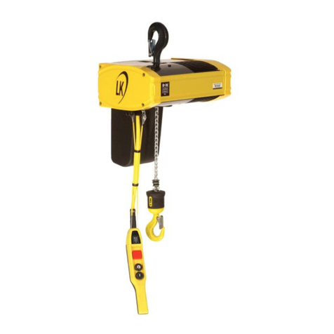
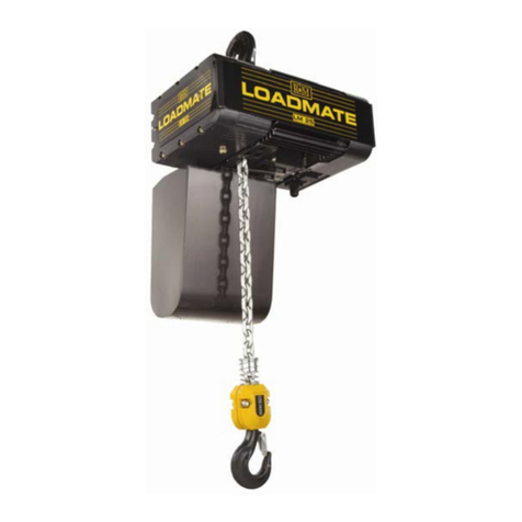
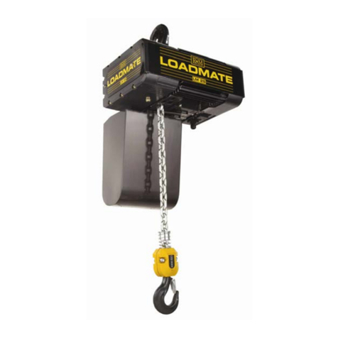
R&M STAGEMAKER SM5 Manual

R&M Materials Handling, Inc STAGEMAKER®COMPACT Concert Hoist
Springfield, Ohio USA SM5 Manual
: 800 955-9967 Revision 1
web: www.rmhoist.com
08/14/02 Bulletin: RM-SM5-MAN-2001-1-ENG.doc
STAGEMAKER
STAGEMAKERSTAGEMAKER
STAGEMAKER®
®®
®COMPACT
COMPACTCOMPACT
COMPACT
Concert
ConcertConcert
Concert Hoist
HoistHoist
Hoist
SM5
INSTALLATION, OPERATION AND MAINTENANCE
INSTALLATION, OPERATION AND MAINTENANCEINSTALLATION, OPERATION AND MAINTENANCE
INSTALLATION, OPERATION AND MAINTENANCE
INSTRUCTIONS
INSTRUCTIONSINSTRUCTIONS
INSTRUCTIONS
JOB
JOBJOB
JOB NO
NONO
NO. :
. :. :
. :
SERIAL NO
SERIAL NOSERIAL NO
SERIAL NO. :
. :. :
. :
(RECORD HOIST SERIAL NUMBER FOR FUTURE REFERENCE)

R&M Materials Handling, Inc STAGEMAKER®COMPACT Concert Hoist
Springfield, Ohio USA SM5 Manual
: 800 955-9967 Revision 1
web: www.rmhoist.com
08/14/02 Bulletin: RM-SM5-MAN-2001-1-ENG.doc
Before proceeding with the installation, operation or maintenance of the hoist it is important that
installation, operating and maintenance personnel read this bulletin carefully in order to ensure
the safe and efficient use of the hoist.
It is strongly recommended that personnel responsible for the operation, inspection and servicing
of this hoist, read and follow the Safety Standard ANSI B30.16-1993 (or current revised edition).
This standard covers Overhead Hoists (under-hung) as promulgated by the American National
Standards Institute and is published by the American Society of Mechanical Engineers. Copies of
this publication are available from the Society at United Engineering Center, 345 East 47th St.,
New York, NY 10017.
If any instructions are unclear, contact the manufacturer or distributor of this hoist before
attempting to install or use the hoist.
IMPORTANT
Electrical wiring diagrams are included with this manual. Also, if an
optional push or motorized trolley has been purchased, a manual is
included with the trolley.
If these items are missing, contact the manufacturer or distributor
before attempting to install or use the hoist.
R&M Materials Handling, Inc.
4501 Gateway Boulevard
Springfield, OH 45502
Tel. 937-328-5100
Fax 937-325-5319
Visit our website: www.rmhoist.com

R&M Materials Handling, Inc STAGEMAKER® COMPACT Concert Hoist
Springfield, Ohio USA SM5 Manual
: 800 955-9967 Revision 1
web: www.rmhoist.com
i
TABLE OF CONTENTS
Section Page
Table of Contents .....................................................................................................i
Foreword...................................................................................................................iii
Warranty.........................................................................................................iii
Parts & Service...............................................................................................iii
Claims for Damage in Shipment....................................................................iii
1. Installation
General ...........................................................................................................1-2
Hoist Configuration........................................................................................1-2
Mounting........................................................................................................1-3
Lubrication .....................................................................................................1-3
Load Hook Throat Opening............................................................................1-3
Power Connections.........................................................................................1-3
2. Initial Start-Up
Proper Hook Motion (Hoist Motor Rotation).................................................2-1
No Load Operational Checks .........................................................................2-2
Torque Limiter................................................................................................2-2
Load/Run Test ................................................................................................2-2
3. Safe Operation Practices
General ...........................................................................................................3-1
Do’s and Don’ts (Safe Operation of Hoist)....................................................3-2
4. Operation/Maintenance
Typical Construction ......................................................................................4-1
Motors ............................................................................................................4-2
Brake/Torque Limiting Device.......................................................................4-2
Operation............................................................................................4-2
Adjustment of the Limiter ..................................................................4-3
Adjustment of the Brake.....................................................................4-4
Frame (Hoist Body)........................................................................................4-5
Load Chain .....................................................................................................4-5
Load Chain Inspection........................................................................4-5
Load Chain Replacement....................................................................4-6
Load Chain Removal..........................................................................4-7
Load Chain Installation.......................................................................4-7
Fall Stop Assembly........................................................................................4-9
Bottom Block, Load Wheel and Suspension Hook........................................4-9
Hook Specification.............................................................................4-10
Suspension Hook................................................................................4-11
Measurement of the Wear on the Suspension and Lifting Hook........4-11

R&M Materials Handling, Inc STAGEMAKER® COMPACT Concert Hoist
Springfield, Ohio USA SM5 Manual
: 800 955-9967 Revision 1
web: www.rmhoist.com
ii
Upper & Lower Limit Switch.........................................................................4-11
Rotary Limit Switch.......................................................................................4-12
Controls..........................................................................................................4-13
AFC Board .........................................................................................4-13
PC Board Controls .............................................................................4-14
Hoist Circuit Diagram - Standard.......................................................4-14
Control Panel..................................................................................................4-15
Circuit Diagram..............................................................................................4-19
5. Preventative Maintenance
Maintenance Table .........................................................................................5-1
Lubricants.......................................................................................................5-2
Spare Parts Replacement Table......................................................................5-2
Screw Tightening Torques..............................................................................5-2
Troubleshooting..............................................................................................5-3
6. Spare Parts Identification

R&M Materials Handling, Inc STAGEMAKER® COMPACT Concert Hoist
Springfield, Ohio USA SM5 Manual
: 800 955-9967 Revision 1
web: www.rmhoist.com
iii
FOREWORD
This manual has been prepared to acquaint you with the procedures necessary for the installation,
operation and maintenance of the hoist you have purchased.
Proper installation is important for the performance of your equipment. Careful study of and
adherence to the instructions will help ensure safe, dependable operation. It is recommended that
this manual be readily accessible to operators as well as maintenance and safety personnel.
Information in this manual is subject to change without notice.
Warranty
R&M Materials Handling, Inc. provides a two (2) year limit warranty on electric chain hoists.
Please contact your Distributor for warranty details.
Parts and Service
R&M Materials Handling, Inc. distributes its products through a network of distributors. Please
contact your Distributor for parts, service, and warranty. A list of R&M Master Distributors is
listed on our website: www.rmhoist.com.
Claims for Damage in Shipment
All shipments are inspected and delivered to our carrier in good order. If damage is observed,
refuse shipment until the carrier makes the proper notation to that effect.
In the event of concealed loss or damage, notify the carrier immediately. By following these
suggestions you will encounter less difficulty collecting your claim.

R&M Materials Handling, Inc STAGEMAKER® COMPACT Concert Hoist
Springfield, Ohio USA SM5 Manual
: 800 955-9967 Revision 1
web: www.rmhoist.com
08/14/02 RM-SM5-MAN-2001-1-ENG
1-1
SECTION 1
INSTALLATION
Figure 1-1
1- Hoist body/motor 5- Chain guide assembly
2- Gears 6- 1-fall hook block
3- Brake/limiter/housing 7- 2-fall hook block
assembly 8- Chain container
4- Chain sprocket with 9- Electrical control panel
output shaft 10-Handle
IMPORTANT
Hoists are designed for lifting of material only. Under no conditions
or circumstances are hoists to be used for lifting or transporting of
personnel. Do not transport any load over personnel without
additional safety precautions.

R&M Materials Handling, Inc STAGEMAKER® COMPACT Concert Hoist
Springfield, Ohio USA SM5 Manual
: 800 955-9967 Revision 1
web: www.rmhoist.com
08/14/02 RM-SM5-MAN-2001-1-ENG
1-2
General
Each complete electric chain hoist is load tested in accordance to ANSI B30.16 at the factory at
125% of nameplate rated capacity, and is usually shipped assembled, unless otherwise stated on
order inquiry.
All hoists are designed for the type of mounting specified by the purchaser. The adequacy of the
supporting members (monorail beams, trusses, hangers, supports, framing, etc.) is the responsibility
of the user and shall be determined by qualified personnel.
Prior to permanent or field installation, units shall be checked thoroughly by qualified personnel for
damage during shipment or handling at the job site. Particular attention shall be taken to make sure
that the load chain and other mechanical or electrical components have not been damaged through
improper handling.
Read the instructions contained in this manual and observe the warning tags attached before
installation is started.
Hoist Configuration
STAGEMAKER®COMPACT concert hoists are offered in five basic configurations, each with its
own control type and hoist features.
ØConfiguration A: Direct motor control without control voltage. Full line voltage controller
furnished separately.
ØConfiguration B: Magnetic controls including a control transformer for controls and controller.
ØConfiguration B1: Standard (upright) hoist mounting position only. PC Board controls
and pendant controller furnished on the hoist.
ØConfiguration B2: Inverted or standard hoist mounting position. PC Board controls
furnished on hoist and controller ordinarily furnished separately.
ØConfiguration C: Programmable controller in conjunction with PC Board controls. Controls
furnished on the hoist and controller furnished separately.
ØConfiguration D: Mandatory safety features are standard. PC Board controls furnished on the
hoist and controller furnished separately.
ØConfiguration E: Variable Frequency Drive (inverter). VFD furnished by others separate from
hoist.
PC Board controls utilize magnetic (low voltage) controls. PC Board controls for the SM5 concert
hoists consist of controls (contactor, transformer, etc.) that are soldered to a circuit board, which
provides most of the internal connections.
WARNING
Before installing the hoist, make certain that the main power switch
supplying power to the hoist is in the open position.

R&M Materials Handling, Inc STAGEMAKER® COMPACT Concert Hoist
Springfield, Ohio USA SM5 Manual
: 800 955-9967 Revision 1
web: www.rmhoist.com
08/14/02 RM-SM5-MAN-2001-1-ENG
1-3
Mounting
The hoist body should be mounted from its suspension hook allowing the body to move in the
direction of the load chain pull and to hang in a straight line between the suspension hook and load
block during hoisting. Non compliance to this principle may result in severe damage to the
equipment. This is true if the hoist is used in the normal or inverted configuration.
Lubrication
The hoist gear reducer is lifetime grease lubricated needing no regular checking or maintenance.
Make sure the load chain is free from contamination or dirt and adequately lubricated with SAE 80
grade oil. Bottom block must hang straight and load chain must be free of kinks or twists.
Load Hook Throat Opening
ANSI B30.16-1993 recommends that the throat opening of the load hook be measured and recorded
prior to putting the hoist into service and that a gage be made to provide a quick visual inspection
for a bent hook as required by monthly inspections. See Section 4.
Power Connections
Make sure that power supply voltage is the same as that shown on the hoist nameplate and that fuses
or other current overload devices are provided to protect the power supply. The power
source/conductors must have sufficient capacity to maintain the voltage at the hoist at ±10% of the
nominal voltage under all operating conditions. Standard nominal voltages are 230 and 460V. Poor
voltage maintenance can cause motor overheating or sluggishness, and chattering or inoperative
motor brakes and controls.
A wiring diagram is included in this manual showing the identification of the power lead
connections. Refer to this wiring diagram prior to start up and/or any electrical work. If the diagram
has been misplaced you may obtain one from R&M upon request. Be sure to mention the serial
number of the unit.
CAUTION
Make sure the main disconnecting switch is off and locked in the open
position before making any electrical connections.

R&M Materials Handling, Inc STAGEMAKER® COMPACT Concert Hoist
Springfield, Ohio USA SM5 Manual
: 800 955-9967 Revision 1
web: www.rmhoist.com
08/14/02 RM-SM5-MAN-2001-1-ENG
1-4
The customer must supply power cable, power distribution set, installation fusing and main
disconnect switch.
Figure 1-2
PS: Power supply connection for hoist configuration A
Combined power and controls for hoist configuration C or configuration D
PB: Controls, hoist configuration B1 or configuration B2
TR: Trolley connection, if motorized trolley is supplied, for hoist configuration B1 only.
Connection:
If the hoist is not supplied with a power cable pigtail or power plug at the hoist electrical enclosure,
then proceed as follows:
1. Remove the control box cover.
2. Insert the cable (PS) into the box through the PG cable gland. Cable gland accepts a
cable diameter of 8-15mm.
3. Connect phases L1, L2, L3 to K10 contactor, and the ground wire to the terminal board
(2).
4. Check that the terminals are correctly tightened, even unused terminals.
5. Tighten the power round cable PG gland.
6. Reinstall the control box cover. (Do not over-tighten cover screws.)
7. Check the hoist operation.
Note: When making electrical connections, refer to the wire identification markers for the various
power and control leads that are shown on the electrical diagrams. By doing so, this will help
prevent improper electrical connections which might cause severe damage to the equipment or
personnel.
Note: This electric chain hoist is furnished with motor and control circuit protection as standard,
which, in the Company’s interpretation, meets requirements of the National Electrical Code in effect
at time of shipment from our factory. The protective devices required for the power feed are
outlined in Article 610 of the NEC and are the responsibility of the user. It is recommended that the
user review Article 610 as well as other applicable Articles of NEC for compliance requirements.
Follow National, State and Local Codes when providing electrical service to the hoist.
Only a qualified electrician shall make all electrical connections.

R&M Materials Handling, Inc STAGEMAKER® COMPACT Concert Hoist
Springfield, Ohio USA SM5 Manual
: 800 955-9967 Revision 1
web: www.rmhoist.com
08/14/02 RM-SM5-MAN-2001-1-ENG
2-1
SECTION 2
INITIAL START-UP
WARNING
Before connecting the hoist to the power supply, check all
“motion” buttons or selector switches on your controller or push
button station to ensure that none of them bind or stick in any
position. Check pendant or controller cables to ensure that they
are not damaged and are wired to desired hoists.
Once power has been supplied to the hoist, several important no-load checks must be made.
Proper Hook Motion (Hoist Motor Rotation)
Since rotation direction of any three-phase AC motor can be changed by reversing any two of the
three lines feeding the motor, it is important that the direction of motion is correct with respect to
the button being depressed, or the selector setting.
To check/correct hook motion (motor rotation), carefully inch the up button and observe hook
motion. If hook does not travel up, stop the hoist and open the main power source disconnect.
WARNING
Do not attempt to reverse hoist motion by changing control leads
in the push button, controller or at the contactor, and do not
change the nameplate on the P/B. Safety switches of the control
circuit wiring as furnished from the factory are directional
sensitive. Changing the push button control leads, wiring inside
the controller or nameplates will prevent the safety switches
from functioning properly. This might create dangerous
situations.
IMPORTANT
Do not run the hoist with the DOWN button if direction is
reversed. To correct the direction of the hook block travel,
reverse any two leads supplying power to the controller, at the
main power source or at the lead in connections to the hoist. Do
not change the internal wiring of the hoist nor the controller.

R&M Materials Handling, Inc STAGEMAKER® COMPACT Concert Hoist
Springfield, Ohio USA SM5 Manual
: 800 955-9967 Revision 1
web: www.rmhoist.com
08/14/02 RM-SM5-MAN-2001-1-ENG
2-2
No Load Operational Checks
üCheck the hoist motor brake function.
üRun the empty hook block up or down to check that the hook drift does not exceed more than
1 inch (25mm). If so, adjust the brake as described in Section 4, Operation/Maintenance.
üRun the empty hook block down to check that the slack fall stop on the free end of the chain
(inside the chain container) makes proper contact with the buffer or the limit switch, if
furnished in place of the buffer. If furnished, check that the limit switch functions correctly.
üRun the empty hook block up to check that the load block makes proper contact with the
rubber buffer or the limit switch, if furnished in place of the buffer. If furnished, check that
the limit switch functions properly.
üRun the empty hook block up and down several times while checking for proper tracking of
the load chain.
Torque Limiter
The electric chain hoist is equipped with a torque-limiting device to help protect against damage
from attempts to lift an over-capacity load. This device is not intended as a measuring device and
shall not be used as such. The device is adjusted at the factory for the rated load capacity of the
hoist. Sound operating practices shall be followed to avoid attempts to lift over-capacity loads.
Load/Run Test
While each complete hoist is load tested at the factory, the user should perform a full load test
after installation of the hoist and completion of no load operational tests.
Lift a near capacity load about 1 foot (30cm) above floor level and check that the brake holds the
load. Also, check the holding capability of the brake when lifting/lowering and stopping the load.

R&M Materials Handling, Inc STAGEMAKER® COMPACT Concert Hoist
Springfield, Ohio USA SM5 Manual
: 800 955-9967 Revision 1
web: www.rmhoist.com
08/14/02 RM-SM5-MAN-2001-1-ENG
3-1
SECTION 3
SAFE OPERATING PRACTICES
General
There is no one single factor that is more important for minimizing the possibility of personal
injury to the operator and those working in the area, or damage to property, equipment, or
material, than being familiar with the equipment and using Safe Operating Practices.
Hoists are designed for lifting and transporting of material only. Under no circumstances, either
during initial installation or in any other use, shall the hoist be used for lifting or transporting of
personnel.
No operator shall be permitted to use the equipment if he is not familiar with its operation, is not
physically and mentally fit, or has not been schooled in safe operating practices. The misuse of
hoists can lead to certain hazards which cannot be protected against by mechanical means;
hazards which can only be avoided by the exercise of intelligence, care, and common sense.
Safe Operating Practices also include a program of periodic inspection and preventative
maintenance (see Section 5). Part of the operator’s training shall be an awareness of potential
malfunctions/hazards requiring adjustments or repairs, and bringing these to the attention of
supervision for corrective action.
Supervisory management has an important role to play in any safety program. They must ensure
that a maintenance schedule is adhered to. Also, that the equipment provided to the operators is
suitable for the job intended without violation of any of the rules covering safe operating practices
and good common sense.
The Safe Operating Practices shown are taken in part from the following publications:
American National Standard Institute (ANSI)
Safety Standards for Cranes, Derricks, Hoists
ANSI B30.2 - Overhead and Gantry Cranes
ANSI B30.16 - Overhead Hoists
Do’s and Don’ts (Safe Operation of Hoists)
The following are Do’s and Don’ts for safe operation of overhead hoist. Taking precedence over
any specific rule listed here, however, is the most important rule of all: USE COMMON
SENSE. A few minutes spent reading these rules can make an operator aware of dangerous
practices to avoid and precautions to take for his own safety and the safety of others. Frequent
examinations and periodic inspections of the equipment as well as a conscientious observance of
safety rules may save lives as well as time and money.

R&M Materials Handling, Inc STAGEMAKER® COMPACT Concert Hoist
Springfield, Ohio USA SM5 Manual
: 800 955-9967 Revision 1
web: www.rmhoist.com
08/14/02 RM-SM5-MAN-2001-1-ENG
3-2
DO’S - HOISTS
1. READ and follow manufacturer’s Instruction, Installation and Maintenance manuals. When
repairing or maintaining a hoist use only manufacturer’s recommended parts and materials.
2. READ and follow all instruction and warning information on, or attached to the hoist.
3. REMOVE the hoist from service and thoroughly inspect and repair, as necessary, if unusual
performance or visual defects (such as peculiar noise, jerky operation, travel in wrong
direction, or obviously damaged parts) are noticed.
4. ESTABLISH a regular schedule of inspection and maintain records for all hoists with special
attention given to hooks, load chains, brakes, and limit switches. See SECTION 5.
5. CHECK operation of brakes for excessive drift.
6. MAKE SURE you never lift loads over people, unless additional safety precautions are taken.
7. CHECK for damaged hooks and load chains.
8. KEEP load chain clean and well lubricated.
9. CHECK the load chain for improper seating, twisting, kinking, wear, or other defects before
operating the hoists.
10. MAKE SURE a load clears neighboring stockpiles, machinery, or other obstructions when
raising, lowering, or traveling the load.
11. CENTER hoist over the load before operating.
12. AVOID swinging of load or load hook when traveling the hoist.
13. BE SURE the load attachment is properly seated in the saddle of the hook. Balance load
properly before handling. Avoid hook tip loading.
14. PULL in a straight line.
15. TAKE up slack slowly.
16. KEEP load chain clear from any objects.

R&M Materials Handling, Inc STAGEMAKER® COMPACT Concert Hoist
Springfield, Ohio USA SM5 Manual
: 800 955-9967 Revision 1
web: www.rmhoist.com
08/14/02 RM-SM5-MAN-2001-1-ENG
3-3
DON’TS - HOISTS
1. NEVER lift or transport a load until all personnel are clear and do not transport the load over
personnel, unless additional safety precautions are taken.
2. DO NOT allow any unqualified personnel to operate hoist.
3. NEVER pick up a load beyond the capacity rating appearing on the hoist. Overloading can be
caused by jerking as well as by static overload.
4 NEVER carry personnel on the hook or the load.
5. DO NOT operate hoist if you are not physically fit.
6. DO NOT operate hoist regular to extreme limits of chain travel against the rubber buffer.
7. DO NOT operate hoist regular to extreme limits of chain travel without first checking for
proper limit switch action if fitted.
8. AVOID sharp contact between two hoists or between hoist and end stops.
9. DO NOT tamper with or adjust any parts of the hoist unless specifically authorized to do so.
10. NEVER use the load chain as a sling.
11. DO NOT divert attention from load while operating hoist.
12. NEVER leave a suspended load unattended.
13. DO NOT use the buffer stop for normal operating stop(s). This effects the setting of the over
load device, which is a safety device only. Adjustment shall be checked on a regular basis for
proper operation (see Section 4.2).
14. DO NOT use limit switches for automatic stops. These switches are a safety device only and
shall be checked on a regular basis for proper operation.
13. NEVER operate any hoist that has an inherent or suspected mechanical or electrical defect.
14. DO NOT use load chain as ground for welding. NEVER touch a live welding electrode to the
load chain. Isolate load hook to prevent grounding.
15. DO NOT jog controls unnecessarily. Hoist motors are generally high torque, high slip types.
Each start causes an inrush of current greater than the running current and leads to over-
heating and heat failure, or burnout, if continued to excess.
16. NEVER place hands on moving load chain or near moving chain pinch points.

R&M Materials Handling, Inc STAGEMAKER® COMPACT Concert Hoist
Springfield, Ohio USA SM5 Manual
: 800 955-9967 Revision 1
web: www.rmhoist.com
08/14/02 RM-SM5-MAN-2001-1-ENG
4-1
SECTION 4
OPERATION/MAINTENANCE
Typical Construction
While each electric chain hoist may have some slight variations in design/arrangement, all hoists
have same basic elements.
1. Motor - basic drive package.
2. Chain Sprocket - moves the load chain to lift and lower the load
3. Gear case Assembly - couples the motor to the chain sprocket
4. Brake/Torque Limiting Device - to stop and hold the load as well as to help prevent lifting of
excessive loads which may damage the hoist.
5. Frame (Hoist Body) - basic structural components that support the load to be handled.
6. Bottom Block and Load Wheel - includes bottom block and chain sprocket.
7. Load Chain - load chain and end connections for picking up the load.
8. Limit Switch – a device for over-travel protection. (Optional for some hoist configurations)
9. Controls - devices for supplying power to motor and reversing direction of the motor.
The following details the operation/maintenance instructions for each basic element. In Figure
4.1 the basic components inside the frame and the basic kinematics are shown.
Figure 4-1
1. Motor
2. Chain sprocket
3. Gear
4. Brake/limiter

R&M Materials Handling, Inc STAGEMAKER® COMPACT Concert Hoist
Springfield, Ohio USA SM5 Manual
: 800 955-9967 Revision 1
web: www.rmhoist.com
08/14/02 RM-SM5-MAN-2001-1-ENG
4-2
Motors
The hoist motors are designed to provide dependable hoisting service. The standard motors are
enclosed for protection against normal hazards of dust and moisture. The bearings are sealed and
lifetime lubricated and they do not require regreasing.
Brake/Torque Limiting Device
The hoist brake is a D.C. disc type. The function of the hoist brake is to minimize hook drift by
bringing the motor to a quick and smooth stop, and to hold loads suspended from the hook with
the power off.
In addition to the hoist brake, the hoist is furnished with a torque-limiting device, integral with
the hoist brake. The torque-limiting device helps prevent the lifting of excessive loads, which
may damage the hoist.
1
346
7
Air gap
2
5
8
X
9
10
Figure 4-2 – Hoist Brake/Torque-limiter
Operation of Brake/Torque-limiter
Even if the torque-limiter slips, once power is removed the brake will engage and hold.
The parts of the limiter and the brake disc are mounted on the gear input shaft (1). Other brake
parts are mounted to the brake housing.
The spring (2) keeps the limiter (3) and the brake discs (4) plated together and defines the
maximum torque that can be transferred through the limiter.
The nut (5) maintains the assembly on the gear-input shaft.
When the coil (6) is energized, during lifting or lowering, it moves against the anchor disc (7),
which is fixed to the brake housing by an attachment screw (10) (there is an air gap for this
purpose). The discs (3 and 4), that are connected together by the friction of the limiter, turn
freely, transmitting the movement to the pinion (8).
Braking occurs when the coil is no longer energized and the spring (9) drives back coil (6).

R&M Materials Handling, Inc STAGEMAKER® COMPACT Concert Hoist
Springfield, Ohio USA SM5 Manual
: 800 955-9967 Revision 1
web: www.rmhoist.com
08/14/02 RM-SM5-MAN-2001-1-ENG
4-3
Adjustment of the Limiter (Refer to Figure 4-3)
WARNING
Make sure that the main switch supplying power to the hoist is in the opened
and locked position before adjusting the torque-limiter.
1. Hook a load of the percentage indicated in the table below onto the hoist.
Configuration A B1 B2 C D E
Test load: % of rated capacity 125% 125% 125% 125% 250% 125%
2. Remove the brake end cap and the seal.
3. Raise the load at slow and fast speed.
4. Turn the adjusting nut (5) in the required direction.
•Turn the adjusting nut clockwise to increase the torque.
•Turn the adjusting nut counterclockwise to decrease the torque.
WARNING
When decreasing the torque, make sure that there is no load connected to the
load block. Failure to remove load from the load block before performing
this procedure may result in personal injury.
5. Repeat steps 3 and 4 until the load can barely be lifted at fast speed. The limiter is now
adjusted.
CAUTION
The limiter will generate heat whenever it is slipping. As a result of this, a
massive clutch plate will absorb most of this heat. When the clutch plate
becomes too hot, adjusting the limiter may be difficult due to unstable
behavior of friction surfaces. If this happens let the limiter cool down for a
while and then readjust the limiter.
6. Fit the brake end cap and seal.
7. Check, at fast speed, the lifting of a nominal load.
WARNING
Never adjust the torque limiter to allow lifting of more than the maximum
capacity shown on the hoist. Failure to adhere to this restriction may result
in personal injury or property damage.

R&M Materials Handling, Inc STAGEMAKER® COMPACT Concert Hoist
Springfield, Ohio USA SM5 Manual
: 800 955-9967 Revision 1
web: www.rmhoist.com
08/14/02 RM-SM5-MAN-2001-1-ENG
4-4
6
7
A
ir gap
2
5
X
10 11
Figure 4-3
Adjustment of the Brake (Refer to Figure 4-3)
The maximum air gap of the brake is 0.022"[0.55mm]. If this value has been reached or will be
exceeded before next inspection, the brake must be adjusted.
WARNING
When adjusting the brake make sure that the main power switch applying
current to the hoist is in open and locked position and remove the load from
the hook. When testing the brake function, be sure not to touch moving and
rotating parts. Before pressing the control button on the pendant station,
check that the adjusting nut is clear of any misplaced items such as tools.
1. Remove the brake end cap and the seal.
2. Measure the air gap between the anchor disc (7) and the outer ring of the coil with a feeler
gauge. Measure the air gap at least at 3 different points around the coil.
3. Set the air gap to 0.012” [0.3mm].
4. Slightly open the three screws, (10) so that the adjustment nut (11) still touches to the brake
housing. Turn the adjustment nut (11) counterclockwise to reduce the air gap. Turning the
adjustment nut clockwise increases the air gap.
5. Check the air gap after adjusting the brake and make sure that the three screws, (10) are
properly tightened to the Torque Specification in SECTION 5.
6. Check the brake function and adjustment.
7. Run the load chain up and down several times without a load to test the function of the brake.
Then, lift a near-capacity load about 1 foot above the floor level and check that the brake
holds the load.
8. Reinstall the seal and the brake end cap.

R&M Materials Handling, Inc STAGEMAKER® COMPACT Concert Hoist
Springfield, Ohio USA SM5 Manual
: 800 955-9967 Revision 1
web: www.rmhoist.com
08/14/02 RM-SM5-MAN-2001-1-ENG
4-5
Frame (Hoist Body)
The frame (hoist body) is constructed of aluminum and, unless damaged from abuse (impact with
another hoist or building structure), requires no maintenance. Any hoist with a frame that is no
longer serviceable for any reason should be referred to the factory for replacement/repair.
Load Chain
CAUTION
A hoist shall never be used if the load chain shows any evidence of
mechanical damage or excessive wear.
The replacement load chain shall be of exact size, grade and construction as the original load
chain that was furnished with the hoist from the factory. Only use R&M load chain as specified
in this manual.
Clean and lubricate the load chain at regular intervals.
Improper load chain storage or installation procedure can render the load chain unusable prior to
the first lift.
Load Chain Inspection
Load chain inspection shall be conducted weekly by a designated person using good judgment in
evaluating the remaining service life. Any deterioration of the load chain resulting in appreciable
loss of the original strength, such as situations described below, shall be noted and evaluated. If
any of the links show cracks or signs of distortion, the chain must be replaced immediately.
A monthly inspection shall include a written record, dated and signed by the inspector.
Test the hoist under load in lifting and lowering directions and observe the operation of the chain
and sprockets. The chain should feed smoothly into and away from the sprockets.
If the chain binds, jumps, or is noisy, first see that is clean and properly lubricated. If the trouble
persists, inpect the chain and mating parts for wear, distortion, or other damage.
Examine visually for gouges, nicks, weld splater, corrosion, and distorted links. Slacken the
chain and move the adjacent links to one side to inspect for wear at the contact points. If wear is
observed or if stretching is suspected, measure the chain for wear as outlined in Load Chain
Replacement Section.
Main items to record regularly:
1. Poor lubrication of load chain.
2. Wear of link on outside and on inside contact points.
3. Crushing, kinking, or signs of distortion.
4. Reduction of original diameter by more than 10%.
During inspections evaluate those sections of chain, which are
normally hidden, such as sections that pass over load wheels.

R&M Materials Handling, Inc STAGEMAKER® COMPACT Concert Hoist
Springfield, Ohio USA SM5 Manual
: 800 955-9967 Revision 1
web: www.rmhoist.com
08/14/02 RM-SM5-MAN-2001-1-ENG
4-6
Load Chain Replacement
Chain Specification: Load chain
Chain type: Standard
Diameter (d) x Pitch (t): 0.189 x 0.492” (4.8 x 12.5 mm)
Class: DAT
Grade: H8S or HE G80 RAS
Maximum working stress: 19,652 lbs/in2(135.5 N/mm2)
Hardened surface: 580 or 700 HV (Vickers Hardness)
Thickness: 0.0039” (0.1 mm) to 0.0079” (0.2 mm)
Standard: DIN 5684 - 8
Marking (10 x t): 1 or 16
H 8 S or A 8
Maximum working load, 1 fall: 1100 lbs. (500 kg)
Breaking load: 6519.50 lbfs (29 kN)
Maximum breaking stress: 116,030 lbs/in2(800 N/mm2)
Total breaking elongation: >10% min.
Unit Weight: lb/ft [kg/m] 0.363 lbs./ft [0.54 kg/m]
Figure 4-4
Measuring the load chain for wear
Measuring the load chain for wear should be performed at several points.
GMeasure the diameter (d) and the pitch (t) of several links.
GMeasure the chain length over 11 links (11 t).
Load Chain Wear Limits:
Minimum link thickness allowed (d): 0.1693” (4.30 mm)
Maximum pitch allowed (t): 0.5157” (13.10 mm)
Maximum length allowed (11 t): 5.5216” (140.25 mm)
If any one of these load chain wear limits is exceeded, the load chain must be replaced
immediately. If a single load chain link is defective in any way, the whole chain must be
replaced. In addition, the chain guide and the chain sprocket must be checked for excessive
wear. If necessary, replace the chain guide and the chain sprocket. A worn chain sprocket or
chain guide usually leads to premature chain wear.
Table of contents
Other R&M Chain Hoist manuals
Popular Chain Hoist manuals by other brands
McBULL
McBULL 9320 manual
XTline
XTline XT108600 Operation manual
Gude
Gude 55103 Translation of original operating instructions
Planeta
Planeta Pullmaster-II Operating and maintenance instructions
SKF
SKF LINCOLN 84827 Series User and maintenance instructions
Power Climber
Power Climber Titan Series operating instructions
SVERO
SVERO 20123A manual
Columbus McKinnon
Columbus McKinnon Yale handy 250 Translated Operating Instructions
Coffing Hoists
Coffing Hoists Concert Series Operating, Maintenance & Parts Manual
SATA
SATA 97871 user manual
Columbus McKinnon
Columbus McKinnon Yale YFS-01 operating instructions

Ingersoll-Rand
Ingersoll-Rand LC2A040S Product Maintenance Information
