2IM 77J01R06-01E 7th Edition
1. MOUNTING METHOD
CAUTION
●Plug/disconnect the main unit into/from the
socket vertically to the socket face. Otherwise the
terminals may bend and it may cause bad contact.
●The converter shall not tilt 5 degrees or more in
either direction when installed.
●When the converter is not connected to the socket,
it is necessary to protect the socket against ingress
of dust to the connector part.
●Keep this product in a conductive bag when
plugged out, during transport or storage.
1.1 Wall Mounting
Loosen the main unit-xing screw of the product and pull out the
main unit from the socket. Fix the socket on the wall with screws.
Next, insert the main unit into the socket and fasten the main unit
with the main unit-xing screw.
29.5 or more
22±0.2
2-M4 or
2-ø
4.5 or more
Mounting Dimensions
Unit: mm
59±0.3
Socket
Threaded hole for
fixing the main unit
Mounting screws
1.2 DIN Rail Mounting
Insert a DIN rail into the upper part of the DIN rail groove on the
rear of the socket, and then slide the slide lock at the lower part of
the socket upwards until the socket is xed into position as shown
below.
DIN rail
(Rear of socket)
DIN rail
Push
1.3 Mounting Using a Multi-mounting Base
When using a multi-mounting base, see the User’s Manual for
VJCE-01A (VJ Mounting Base for communication) (IM 77J01C51-
11E).
1.4 Using a Duct
When using a wiring duct, install the duct at leaset 30 mm away
from the top and bottom faces of the main unit.
2. INSTALLATION AND ENVIRONMENTAL
CONDITIONS
• Avoid the following environments for installation locations:
Areas with vibrations, corrosive gases, dust, water, oil,
solvents, direct sunlight, radiation, a strong electric eld,
and/or a strong magnetic eld, direct radiant heat, wind,
temperature uctuation, 2000 m or more above sea level,
outdoors.
• If there is any risk of a surge being induced into the power
line and/or signal lines due to lightning or other factors, a
dedicated lightning arrester should be used as protection for
both this unit and a eld-installed device.
• Use indoors at an altitude of 2000 m or less.
• Operating temperature/humidity range: −10 to 55°C (−10
to 45°C for side-by-side mounting*)/5 to 90%RH (no
condensation)
* If the previous model (style S3.xx earlier) is installed
together, the ambient temperature is 0 to 40°C.
• Continuous vibration: (at 5 to 9 Hz) Half amplitude of 3 mm or
less (at 9 to 150 Hz) 9.8m/s2or less, 1 oct/min for 90 minutes
each in the three axis directions
• Impact: 98 m/s2or less, 11 ms, 3 axes, 6 directions, 3 times
each
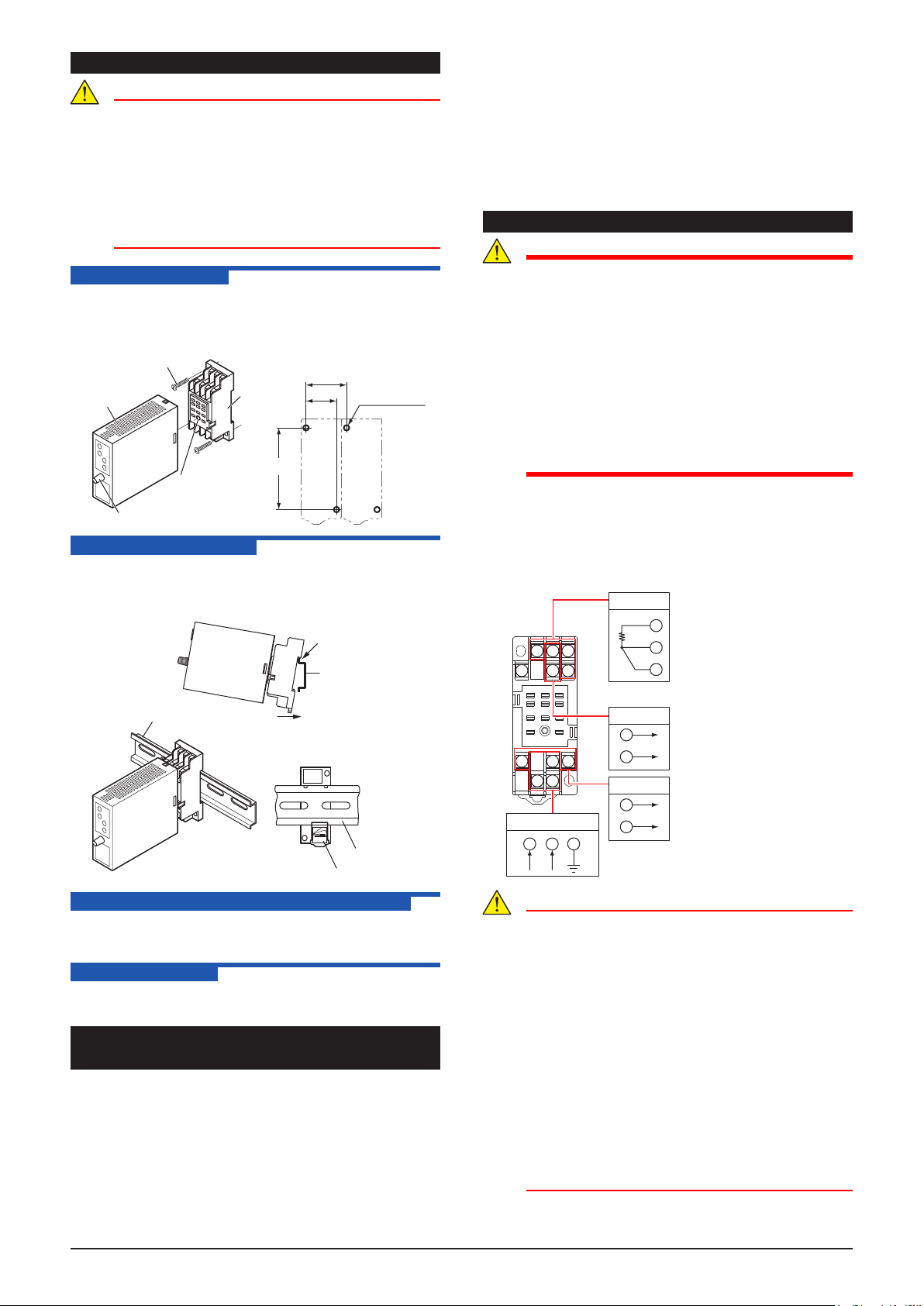
3. EXTERNAL WIRING
WARNING
●To avoid the risk of an electric shock, turn o the
power supply and use a tester or similar device to
ensure that no power is supplied to a cable to be
connected, before carrying out wiring work.
●Do not operate the product in the presence of
ammable or explosive gases or vapors. To do so is
highly dangerous.
●Use of the product ignoring the specications may
cause overheating or damage. Before turning on
the power, ensure the following:
• Power supply voltage and input signal value
applied to the product should meet the required
specications.
• The external wiring to the terminals and wiring to
ground are as specications.
Wiring should be connected to the terminals on the socket
of the product. The terminals for external connections are of
M3 screws. Use crimp-on terminal lugs for connections to the
terminals.
Recommended cables: A nominal cross-sectional area of
0.5 mm2or thicker for signal cables, and that of 1.25 mm2or
thicker for power cables.
1011
3 2 1
4
56
789
1
3
4
Output-1
Power supply
1110 8
L+ N– GND
7
9
B
B
A
Output-2
Input
2
5
The wiring resistance of input terminals 1
and 3 should be the same.
When the style is VJR6 of 1.0 and 2.0
The wiring resistance of input terminal 1
and 4 should be the same.
+
–
+
–
CAUTION
●Do not use output-2 for the isolated single-output
type.
●The power line and input/output signal lines should
be installed away from noise-generating sources.
Other wise accuracy cannot be guaranteed.
●Make sure to earth ground the ground terminal
through minimum resistance. The length and
thickness of the grounding cable should be as
short and thick as possible. Directly connect the
lead from the ground terminal (terminal no. 8) of
the product to the ground. Do not carry out daisy-
chained inter-ground terminal wiring.
●The product is sensitive to static electricity;
exercise care in operating it. Before you operate
the product, touch a nearby metal part to discharge
static electricity.
●If the ambient temperature is 50 °C or more, please
use the cable that the rated temperature is 70 °C or
more.


