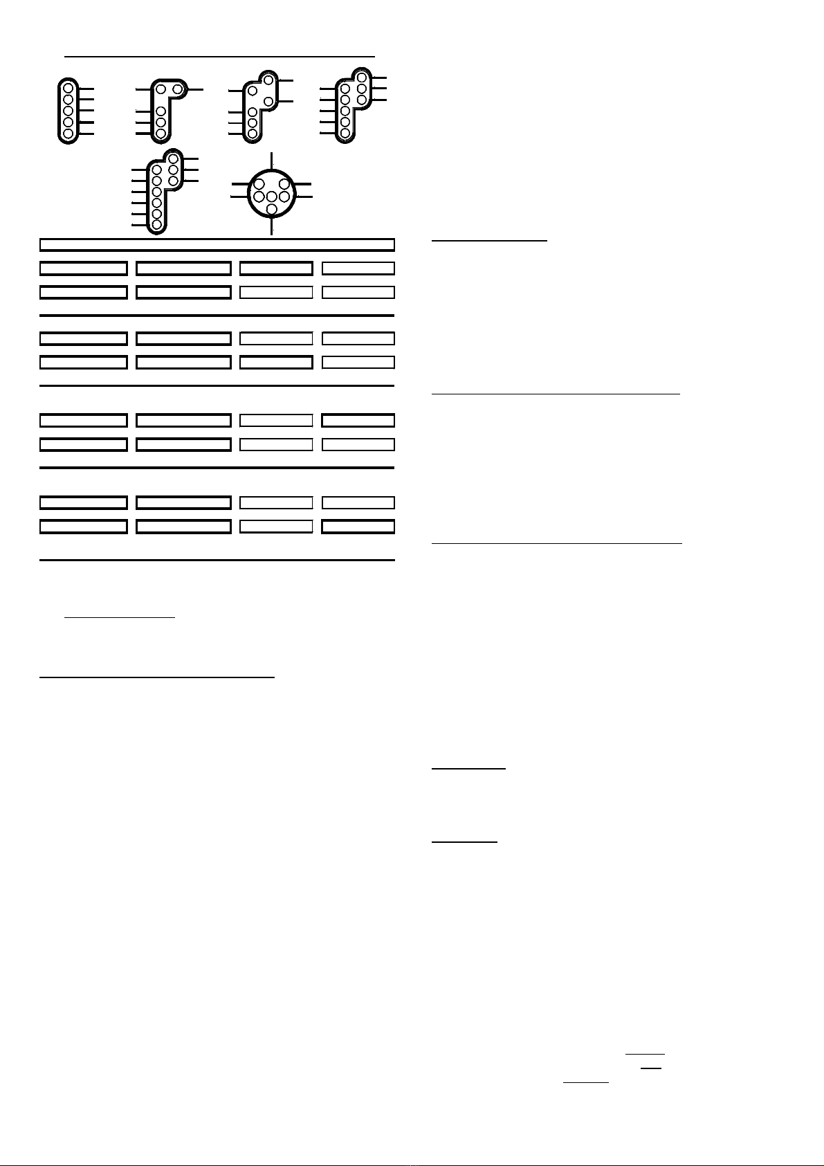
2. One up to 16-aspect Signal on each clamp bar:
GN
GE
RT1
RT2
WS
GE
RT1
RT2
GE1 GE2
RT1
RT2
GN GN1
GN2
GE
GN
RT1
RT2
GE1 GE2
GN1
GN2
GE
GN
RT1
RT2
GE1 GE2
GN1
GN2
GE
WS
GE
RT2
RT1
GE2GE1
GN
Further sample connections are available at the internet on our Web-
Site (www.ldt-infocenter.com) at the section “Sample Connections”.
Additionally you can find detailed information about the Light signal-
decoder LS-DEC-SNCF at our Web site within the section “Digital-
Compendium” at chapter 2.
Programming the decoder address:
•The jumper J3 has to be inserted for the programming of the
decoder addresses.
•Switch-on the power supply of your model rail way.
•Activate the programming key S1.
•At least two light emitting diodes on a signal connected to the
left clamp block (on this decoder side is the programming key S1)
will be automatically switched over every 1.5 seconds in a
flashing mode. This indicates that the decoder is in the
programming mode.
•Press now one key of the fourfold address-group to be
assigned to the left clamp block of the decoder. For programming
the decoder address you can as well release a turnout switch signal
via your model railway software.
•Remarks: The decoder addresses for magnet accessories also
to be used for switching the signal-aspects are combined into
groups of four. The address 1 to 4 will be the first group. The
address 5 to 8 will be the second group etc. Each clamp block of a
LS-DEC decoder can be assigned to any of these groups. It does
not matter which of the eight possible keys used for programming
will be activated. The decoder stores always the complete group of
keys.
If the Light-Signal Decoder LS-DEC shall control on this clamp bar
two 2 to 4 aspect signals or one up to 16 aspect signal this has
to be adjusted together with the decoder address. If you activate
within the programming mode one key of the desired group of four
keys designated for switching a turnout straight or a signal to
green the decoder will be set for the controlling of two 2-to 4-
aspect signals.
If you activate a key for switching a turnout round or a signal to red
you have selected the option to switch one up to 16-aspect signal.
For both programming modes (left and right clamp bar) you can
individual select if two 2-to 4-aspect signals or one up to 16-
aspect signal shall be digital controlled.
•If the decoder has recognized the assignment correctly the
connected light emitting diode will flash a little faster. Afterwards
the flashing slows down to the initial 1,5 seconds again.
In case the decoder will not recognize the address it could be that
the two digital information connections (clamp 2) are wrong
connected. For testing this, switch off the power supply, exchange
the connection on KL2 and start addressing again.
•Press now the programming key S1 again. At least two light
emitting diodes connected to the right clamp block will flash now.
Repeat the programming of this fourfold-address block as
described above.
•Now press the programming key S1 a third time for leaving the
programming mode. All signals will be automatically switched to
STOP.
Signal switching:
The opposite sample connections show how the fourfold address-
group can be set by use of 8 keys of the push button panel for setting
the turnouts or signals. Between each pair of keys are e.g. the
addresses 1 to 4. The two keys red and green for each address are
assigned to the turnout position round or straight respectively the
corresponding signal aspect which is indicated above or below the
key. The actual address section is related to which fourfold address-
group has been selected during the programming.
If you use a remote control LH100 of Company Lenz Elektronik then
red will be the minus key and green the plus key.
1. Two 2-to 4-aspect signals on each clamp bar:
If you have adjusted the Light-signal decoder LS-DEC-SNCF for
switching two 2-to 4-aspect signals by programming one clamp
bar as shown at the picture under 1. on the first page of this instruction
you can e.g. switch the first signal to drive (Voie libre VL) with
address 1 and key green.
Please activate the key green of the address 3 and the second signal
will be switched to drive (Voie libre VL).
The first signal will be always switched via the address 1 and 2. The
second signal of the clamp bar will be switched via the address 3
and 4 of the programmed four fold address group.
2. One up to 16-aspect signal on each clamp bar:
If you have adjusted the LS-DEC-SNCF by programming the address
of one clamp bar for switching one up to 16-aspect signal the picture
left under 2 will indicate the status.
Via the two first addresses of the clamp bar of this programmed four
fold address group is it possible to switch four signal aspects.
As a total of 16 signal aspects can be controlled the selection of one of
four signal aspect groups has to be performed via the addresses 3
and 4. The occupancy of keys below the signal shows the relation. After
switching–on the signal indicates stop (Carré C). If now e.g. the aspect
Ralentissement 30 Rshall be indicated is it required at first to activate
the address 4, key red for the third signal aspect group and then the
address 1key red.
Only the thick framed keys of the table will be required for switching
the signal.
Accessory:
For the assembly of the LS-DEC below your layout base plate we offer
an assembly set under the order code MON-SET. For the assembled
kits and the finished modules we offer a suitable case under the order
code LDT-01.
Attention:
The Light signal decoder LS-DEC switches the signal aspects not just
on and off but is dimming the light emitting diodes realistic up and
down. Even between the signal aspects a short off-phase is provided.
Further digital commands received during this switch-over-time of about
0,4 seconds will not be taken up from the decoder. Please take care
that the switching-commands are not in a too fast sequence. The
impression is absolutely realistic if the switching is considerable slow.
If the jumper J3 will be removed after programming of the decoder
addresses the memory storage of the Light signal decoder LS-DEC
will be protected against any alteration.
Made in Europe by
Littfinski DatenTechnik (LDT)
Kleiner Ring 9
D-25492 Heist/Germany
Phone: 0049 4122 / 977 381
Fax: 0049 4122 / 977 382
Internet: http://www.ldt-infocenter.com
Subject to technical changes and errors. 07/2015 by LDT
Märklin and Motorola are registered trademarks.


