Manual-4
Setup Methods
e goal is to design a 3-way or 4-way system with the flattest
possible response and good dispersion. Two practical methods
for crossover setup follow:
1. Use relatively low levels of pink noise and close microphone
placement (18 to 36 inches)[45 to 90 cm] to minimize the
effects of room acoustics. Once the system is tuned, lock the
crossover behind a security cover.
2. Use measurement tools designed to analyze installed sys-
tems. Professional system analysis tools are available that can
discriminate between room acoustics and system response.
SIA Software Company, Inc., have developed tools, including
SmaartLive and SIA Acoustic Tools, that allow sound system
measurement and acoustic analysis. e software is designed
for serious pro audio and acoustical consultant engineers. For
more information visit www.siasoft.com. Once the system is
tuned, lock the crossover behind a security cover.
Setup Instructions
e following crossover setup procedure is based on the use of
close microphone placement with the system installed. e pro-
cedure requires a real-time analyzer, pink noise source and SPL
meter. As luck would have it, the Rane RA 30 is equipped with
all three. ere are five steps:
STEP ONE: Select Crossover Frequencies
STEP TWO: Adjust Signal Delay
STEP THREE: Set CD Horn EQs (if required)
STEP FOUR: Set Output Levels
STEP FIVE: Set Limiters
Note: If you are running two Channels, tune up only one Chan-
nel at a time, unless the STEREO LINK is used.
STEP ONE: Select Crossover
Frequencies
Most speaker manufacturers supply low and high frequency cut-
off points for each driver. ese cut-off frequencies are based on
each driver’s response limitations, physical limits and safe operat-
ing area. Most specifications allow a safety margin to accommo-
date gentler filter roll-off.
e AC 24 utilizes continuously adjustable frequency selec-
tors. Each precision potentiometer provides 64 steps covering 3.3
octaves (.05 octave per step). is resolution assures consistent
accuracy.
e AC 24 possesses 24 dB per octave roll-off, so the cross-
over points are easily set with the accuracy required to avoid
hazard to the driver or degradation in sound quality.
For best results, choose speaker components so each oper-
ates well within its recommended limits with adequate response
overlap. is provides valuable leeway in crossover frequency set-
tings and helps ensure the flattest possible system response. Extra
margin also yields higher system reliability. If possible, always use
some kind of realtime analyzer to tune your crossover.
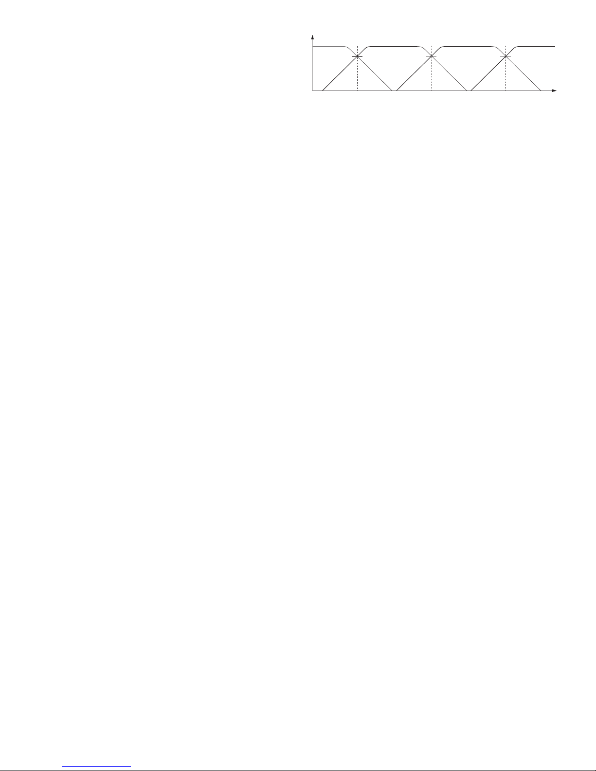
Figure 1 shows typical driver responses for a 4-way sys-
tem and the selected crossover frequencies. Select each drivers
response and set each crossover frequency to allow significant
overlap in response.
After Crossover Frequency settings are made based on driver
data, the best way to proceed is with a realtime analyzer (see the
Rane RA 30, page Manual-8). Using a realtime analyzer allows
verification of crossover settings and adjustment of output levels
to compensate for the sensitivity of individual drivers.
STEP TWO: Adjust Signal Delay
Before jumping feet first into the realm of signal delay compen-
sation, it helps to re-affirm why delay is necessary. For a short
course on signal delay and Linkwitz-Riley crossovers, we recom-
mend the “Linkwitz-Riley Crossovers” RaneNote. Ask your
dealer, call us at the factory, or get it from our website.
Let’s review the basic effects of signal delay in crossovers.
Problems pop up when two different speakers emit the same
frequency in the crossover regions. Because the two drivers are
displaced vertically, cancellation occurs somewhere off-axis be-
cause the sound waves have to travel different distances from the
two speakers and hence, arrive out of phase. is forms a “lobe”
or radiation pattern, narrowing the listening-area of the speaker.
Fine, so we put up with it.
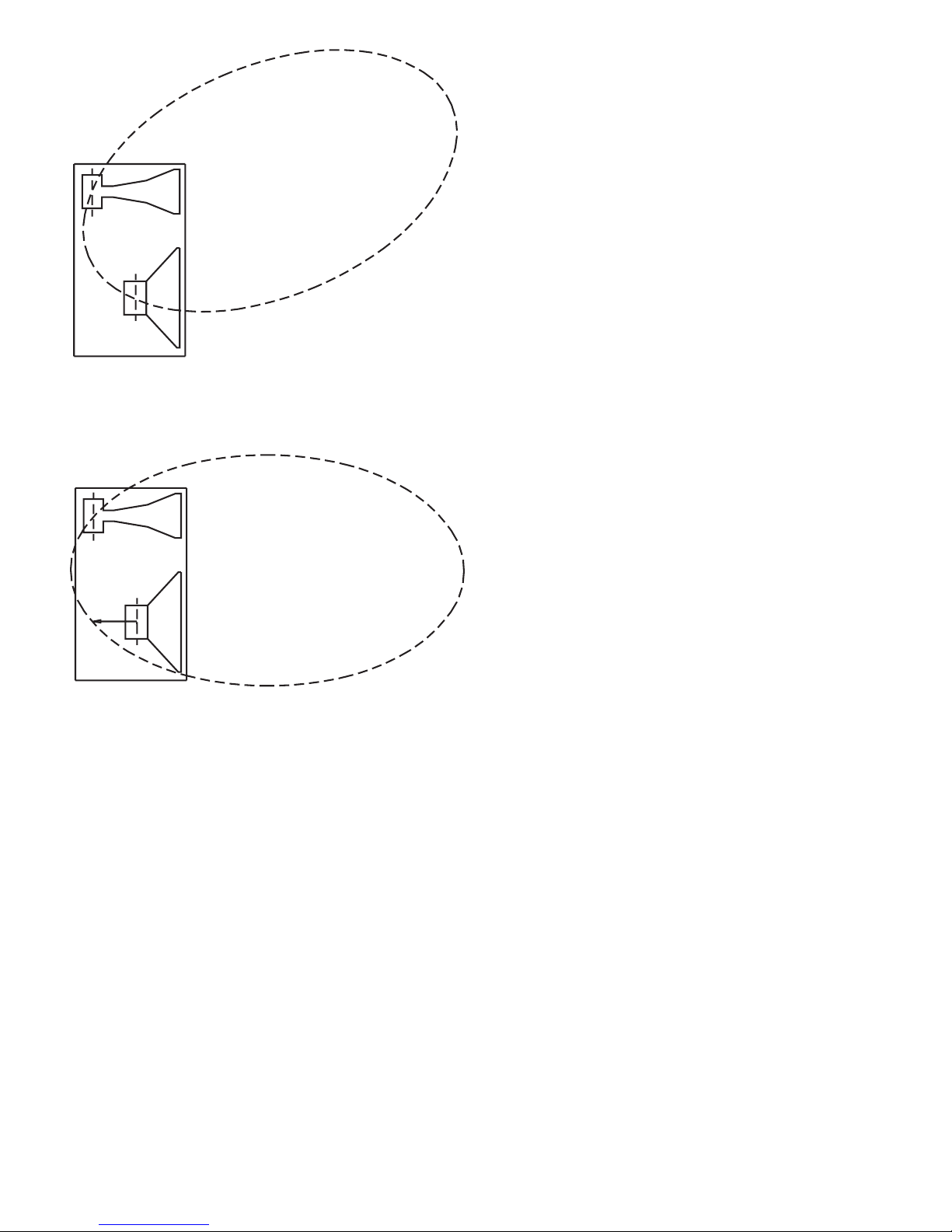
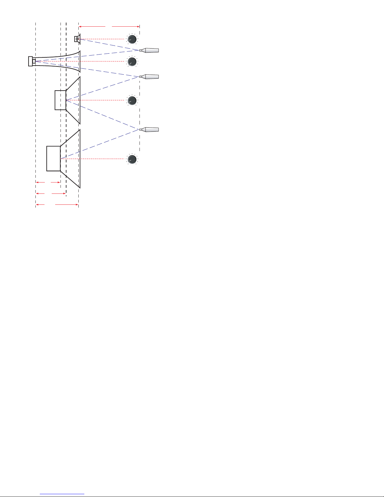
To make matters worse, when two drivers are horizontally
displaced—that is, one is in front of or behind the other, this
“lobe” or dispersion pattern gets tilted toward the driver that is
further behind (see Figure 2). e result is a speaker system with
two, three, four or more tilted radiation patterns.
In an ideal system, all drivers are aligned in the same vertical
plane and all components are in phase. With main lobes on-axis
and well behaved, the system has the widest possible dispersion
pattern and everyone gets good sound. Unfortunately, it’s often
physically impossible to place all the driver sound sources in the
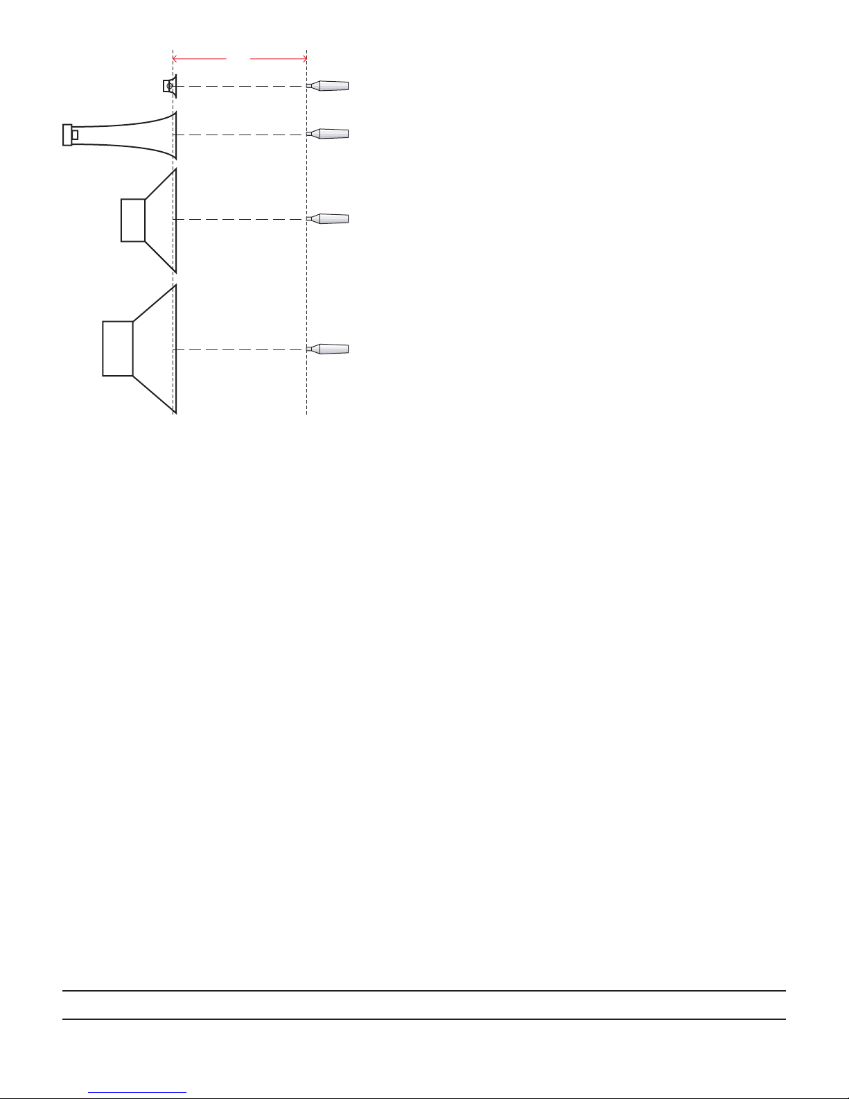
same vertical plane. Fortunately, by electronically delaying the
signal going to the front driver, the sound from the rear driver is
able to catch up. e result is signals from both drivers arriving
in phase with correct acoustic summing (see Figure 3).
e trick is finding the proper signal delay amount: hence the
rest of this section. It is possible to get good results by setting the
required signal delay based exclusively on horizontal displace-
ment as outlined in Signal Delay Method One. Ideally, using
true delay in combination with phase compensated crossover
filters, would make the required signal delay independent of the
crossover frequency. If true, the required delay could be deter-
mined solely by the horizontal displacement between driver voice
coils. e world is seldom ideal. e drivers themselves introduce
phase shift that must be accounted for. erefore, best results
are achieved by calibrating the required delay outlined in Signal
Delay Method Two.
Figure 1. Driver responses and crossover points
Mid frequency Hi-Mid frequency
0 dB
Amplitude (dB)
Frequency (Hz)
Low pass 100 Hz 500 Hz 4 kHz
s
l
o
p
e
= n d
B
/
octave
High pass
Low / Mid Mid / Hi-Mid Hi-Mid / High
s
l
o
p
e
= n d
B
/
octave