RAPA L-BK User manual

1
TRANSLATED FROM
ORIGINAL USER
MANUAL
REFRIGERATED FLOWER COUNTER
L-BK
05/2022
EN

Table of contents
1. Application and device code meaning
4
2. Product characteristics
5
3. Cooling system diagram
5
4. Wiring system
5
5. Wiring system diagram
6
6. Drawings
7
7. Positioning, start-up and operation
9
8. Maintenance
9
9. Transport and equipment
10
10. Temperature controller manual
10
11. Notes
14
12. Interferences
14

3
Please read this user manual carefully before using the device
and keep it for future reference.
Following the manual's recommendations guarantees long-lasting and
failure-free exploitation of the device.
IT IS FORBIDDEN
1. Make repairs on your own and fail to comply with the rules contained in
this manual regarding the connection and operation of the device;
2. Store substances that may explode in the device, such as aerosols
filled with combustible propellants;
3. Place the device in the sun;
4. Covering the inlet and outlet of air from the aggregate;
5. Switching the device on to the mains without a properly
functioning protective circuit system;
6. Use of extension cords and dividers to connect power.
7. Use devices/objects that could cause an electric spark inside
the device and in the aggregate chamber.
WARNING!
1. Incorrect connecting of the device to the mains may result in an
electric shock.
2. In the event of sparks or breakdowns, immediately disconnect the
device from the power supply by pulling the plug from the socket and
calling an authorized service technician.
3. It is necessary to protect the wiring system and control system
against water and mechanical damage.
4. When servicing and replacing parts, the device must be
disconnected from the power supply
CAUTION!
1. Before cleaning the condenser –switch the device off!
2. When cleaning the condenser, do not use tools/objects that could
cause an electric spark.
3. Water condensation on glass panes and sheets at high relative
humidity (over 60%) is a natural phenomenon. Long-term and frequent
occurrence of dewing indicates inadequate ambient conditions and is
not a basis for calling the service!
4. Take care when removing the glass panes.
Breaking the glass panes can cause injury!
i
t
The device is not intended for household use.
The device is not intended for outdoor use.
!
!

4
1. APPLICATION AND DEVICE CODE MEANING
The device is stationary-type equipment intended for storing and expose food
cut flowers at a reduced temperature.
DEVICE CODE MEANING
Example of device code:
L-BK/118/95
L–type of the device: refrigerated counter
BK –model: flower counter
118/95 –device dimensions (see table point 2)
Important information on the rating label of each device:
In the case of contact with the service
department, prepare the following data
for efficient service:
device type,
serial no
Climatic class means the maximum ambient temperature
at which the device works without disturbances.
Climatic class 3
maximum permissible ambient temperature of +25°C,
temperature test:
ambient temperature +25°C ± 1°C
humidity 60% ±3%
Name, logo, and type of device
Device technical parameters
Manufacturer contact details

5
2. PRODUCT CHARACTERISTICS
rated voltage: 230V~ / 50Hz
refrigerant: HC-290; ODP = 0, GWP = 3
working temperature: +1°C ÷ +10°C
sound pressure level: <70dB (A)
3. COOLING SYSTEM DIAGRAM
4. WIRING SYSTEM
1.The device is equipped with the protective PE cable.
2.Before connecting the device to the power supply, check the compatibility of the mains
voltage with the device supplying voltage (data on the plate).
3.Connecting the device to the mains socket should be made so that the plug of the
connecting cable is visible and easily accessible for the service.
4.The device should be connected to a separate, properly made electrical circuit
protected by a fuse no greater than 10 A with a B-characteristic, ended with a socket
with a protective pin.
5.The device may be started only after confirming the effectiveness of the shock
protection with the results of measurements carried out in accordance with the
applicable regulations.
6.Before carrying out any maintenance or cleaning, turn off the device with the switch
and then remove the plug from the mains socket.
7.The device is started after connecting the plug to the mains socket, and then by turning
on the switch. The backlight of the switch indicates that the device has been turned on.
8.Any repair of electrical installation and replacement of the connection cable (only into
original one available from the manufacturer) may be carried out by an authorized
electrician only.
Catalogue length/depth
of the device
[cm]
Device height
[mm]
Exposition
surface
[m2]
Maximum quantity of
containers for
flowers
(diameter 250 mm)
Maximum
load
[kg]
closed
open
820/950
1180
1910
0,5
6
50
1180/950
0,8
9
90
1450/950
1,0
12
120
capillary
chemical filter
condenser
compressor
evaporator

6
5. WIRING SYSTEM DIAGRAM
SPR –compressor
WA –aggregate switch
MS –condenser fan
MN –evaporator fan
CKO –defrost ending sensor
CRT –electronic temperature regulator sensor
REG –electronic temperature controller

7
6. DRAWINGS
Pic. 1
mirror
side glass pane
front glass pane
air guide glass pane
insert shelf
(exposition elevation)
defrost water
collection container
condenser
evaporator
compressor
fan

8
Pic. 2
C-shape of side glass pane
pin for supports
(for mirror closing during
shop being closed)
* There is possibility to close the mirror for transport and operation of the device during the time
of shop being closed. In order to do it there should be two persons on side of the device, grab
the mirror by means of its sides, lift upwards and tilt the device forward. Then, properly place the
appreciate elements of the device against each other (descriptions in the picture).
In order to spread the mirror it is necessary to do it in reverse sequence.
A detail
B detail
The method of opening the aggregate protective grid
supports for mirror on pins
(for mirror closing during shop being closed)
bumpers supporting mirror on
C-shape of side glass panes
mirror *
pocket for price list
protective grid of aggregate
aggregate switch
electronic temperature controller
cover for defrost water
collection container
4 swivel wheels (2 with break)

9
7. POSITIONING, START-UP AND OPERATION
To ensure proper operation, the device should be placed in an area with a good air circulation,
away from heat sources and sunlight, free from dust (the device is not dustproof), at ambient
temperature from +16°C to +25°C – 3rd climatic class. The manufacturer is not responsible
for interferences of the device operation in temperature beyond given range for 3rd climatic
class.
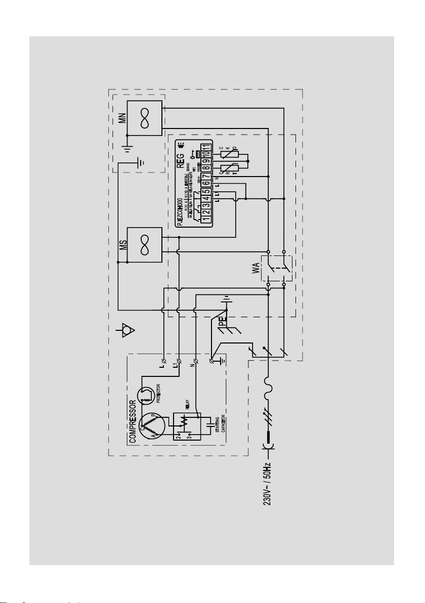
Place the device horizontally and connect it to the power supply according to the guidelines
included in the chapter No. 4 - “Wiring system”.
WARNING:
The device cannot be placed below the floor level (in a hollow).
The room in which the device is located must have a minimum cubature of 4 m3.
Start-up and exploitation:
The aggregate are switched on and off by means of the switches shown on picture
in the chapter No. 6. The temperature inside the device is adjusted by means of the electronic
temperature controller, according to the instructions included in the chapter No. 10.
After switching the device on, leave it empty until its switching off for the first time. After that it is
ready to be filled with products.
Maximum load (see table in chapter 2) should be distributed evenly on whole area of exposition.
Water collection container should be emptying when necessary.
8. MAINTENANCE
After disconnecting the device from power supply, the general maintenance should be done
by the user, as follows:
1. washing with water of the temperature not more than +40°C with addition of natural cleaning
agents. To wash and clean the device it is forbidden to use agents containing of chlorine
and sodium of various varieties, which destroy the protective layer and components
of the device! Any residual glue or silicone on the metal parts of the device should be removed
only with gasoline (not applicable to plastic components!).
Do not use other organic solvents.
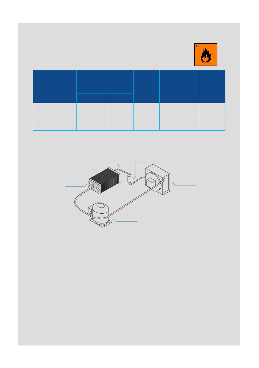
2. removing impurities from the condenser by means of vacuum cleaner (from up to down -
along the fins) at least once a month so that the flow of the cooling air through the condenser
fins is not hampered.
Not following the above instructions causes increased energy consumption, decreased
refrigeration efficiency of the device and eventually result in aggregate overheating,
which consequently may lead to failure.
While cleaning the condenser be careful not to deform the fins.
Do not wash the device with a water jet.
It is not advisable to clean the condenser with a brush as it causes impurities penetration
deep into the condenser fins and finally block the air flow completely.
CLEAN THE CONDENSER WITH A VECUUM CLEANER HERE

10
9. TRANSPORT AND EQUIPMENT
While transporting secure the device to prevent its overturning, damage of the paint
coat and breaking of the glass elements. When handling the device do not press the
glass elements, do not grab the door or aggregate protective crate to lift the device. It
is best to use belts and place them under the frame, between the feet (so that the
belts do not slide). Do not lift the device directly with a forklift or a pallet truck without
a palette, as it may damage the aggregate.
The device must be transported in its working position!
Equipment: user manual, defrost water collection container
10. TEMPERATURE CONTROLLER MANUAL
DISPLAY DESCRIPTION
The display is three digits with decimal point and 6 symbols (compressor, fan,
defrost, AUX, alarm and clock).
1. COMPRESSOR
The symbol is visible when the compressor operates. It flashes when the
compressor’s start up is delayed because of protective procedure. It flashes in the
cycle: two flashes –break when there is continuous operation mode activated.
1. COMPRESSOR
The symbol is visible when the compressor operates. It flashes when the
compressor’s start up is delayed because of protective procedure. It flashes in the
cycle: two flashes –break when there is continuous operation mode activated.
2. FAN
The symbol is visible when there are evaporator fans switched on. It flashes when
the fans start-up is delayed by means of external switching off or when there
is other procedure in progress.
3. DEFROST
The symbol is visible when there is defrost function switched on. It flashes when
the defrost start-up is delayed by means of external switching off or when there is
other procedure in progress.
4. AUX
The symbol is visible when there is additional AUX output activated.
5. CLOCK
The symbol is visible when there is clock switched on –switching on by means of
„tEn” switch or when there is time limit set. When switching on the symbols
appears for few seconds as clock function availability.

11
6. ALARM
The symbol is visible when there is alarm activated.
SWITCHES DESCRIPTION
Information: Short pressing of any of the switches causes appearance of
message related to the currently active function.
7. UP / ON OFF
During normal operation of the controller; pressed for longer than 3 sec. will
cause change of controller ON/OFF operation state, pressed along with the
“DOWN” switch at the same time for longer than 3 sec. will cause activation or
deactivation of continuous operation function (after pressing there will be shown
on the display “CC” symbol). In the parameters setting mode: enable going to the
next parameters settings. During setting parameter values: it causes parameter
value increase.
8. SET / MUTE
Pressed during normal controller operation switches the alarm sound signal off;
pressed for longer than 3 sec. shows setting point; pressed along with the
“DOWN” switch at the same time while switching power supply of the controller
on will cause return to the parameters fabric settings (there will be shown “CF”
symbol on the display). In the parameters setting mode: its pressing changes the
information shown on the display: parameter name/parameter value, pressed for
longer than 3 sec. will cause saving of the set parameters. During setting
parameter values: pressed it will cause saving of the entered parameter value.
9. DOWN / DEFROST
During normal operation of the controller; pressed for longer than 3 sec. will
cause switching on/off of the manual defrost mode. In the parameters setting
mode: it allows to go to previous parameter setting. During setting parameter
values: it decreases setting value.

12
Set point setting (desired temperature value)
To view and modify the set point:
press the “SET” switch for 1 sec. – the set value will start flashing;
increase or decrease the value using the “UP” or “DOWN” switches;
press the “SET” switch to confirm the new value.
If the “SET” switch is not pressed for 60 sec., then the controller returns to
previous settings.
Manual defrost
In order to activate the manual defrost press the “DOWN” switch for more than
3 sec. The essential condition is the temperature has to be lower than +6°C.
Temperature checking on the defrost probe
press the “SET” switch for longer than 3 sec. (in case there is the alarm is
activated it is necessary to switch the sound alarm off first). On the display
there will appear “PS” symbol (password);
go to the “d/” parameter be means of the “UP” and/or “DOWN” switches, then
press the “SET” switch - there will appear temperature of defrost probe and
the symbol or
hold the “SET” switch for longer than 3 sec. (after 60 sec. automatic return) –
return to the temperature probe indication.
Access for operator to parameters configuration and its modification
press the „SET” switch for longer than 3 sec. (in case there is alarm activated,
switch the sound alarm first). On the display will appear the „PS” symbol (service
parameter password protected);
go to the next parameters by means of the “UP” and/or “DOWN” switches;
press the “SET” switch to view the current value of parameter setting;
increase or decrease setting value by means of the “UP” and “DOWN” switches;
press the “SET” switch to temporarily save the entered new value – it will cause
as well return to the parameters list;
repeat the above operations –if it is necessary;
press and hold the “SET” switch for longer than 3 sec. – it will cause parameters
saving and exit from the programming procedure.
Warning:
If no button is pressed for 60 sec., all the changes made to the parameters,
temporarily saved in the RAM, will be cancelled and the previous settings restored.
If power is disconnected from the instrument before saving the settings (pressing
the “SET” switch for 3 sec.), all the changes made to the parameters and
temporarily saved will be lost.

13
Description of the main signals and alarms
LED flashing –The activation of the corresponding function is delayed by a timer
awaiting an external signal or disabled by another procedure that is
already in progress. e.g. if is a continuous cycle in progress and a defrost is called,
the latter will remain pending until the end of the continuous cycle, and the
corresponding LED (defrost) will flash.
OFF flashing –state of the controller - OFF, to return to working mode (ON)
press and hold ON/OFF button for more than 3 sec.
E0 steady –temperature control probe error (1) –active sound signal:
probe not working: the probe signal is interrupted or short-circuited;
probe not compatible with the instrument.
The E0 alarm signal is constant when it is the only active alarm (the temperature
value is not displayed).
E0 flashing –temperature control probe error (1), when other alarms are active
or the second probe is displayed.
E1 flashing –evaporator probe error (2):
probe not working, the probe signal is interrupted or short-circuited;
probe not compatible with the instrument.
Ed flashing –The last defrost ended after exceeding the maximum duration rather
than when reaching the end defrost set point. The message disappears when the
next defrost ends correctly.
EF displayed during operation or on power-up –operating parameter reading
error (controller automatic reset). Alarm reappearance after automatic reset –it is
necessary to check the controller as there is no guarantee to keep the original
precision of the operation.
Symbol
Parameter
Unit
Fabric setting
min.
max.
d8
Alarm bypass time after defrost
h
2
0
15
A0
Alarm and fan temperature differential
°C
2
0
20
AL
Absolute or relative temperature for low
temperature alarm
°C
2
0
150
AH
Absolute or relative temperature for high
temperature alarm
°C
8
0
150
Ad
Temperature alarm delay
min
60
0
199
High temperature alarm activation = setting + AH
High temperature alarm deactivation = setting + AH –A0
Low temperature alarm activation = setting –AL
Low temperature alarm deactivation = setting –AL + A0

14
EE –data errors –In certain operating conditions, the instrument may detect errors
in the data saved. These errors may compromise the correct operation of the
instrument. If the microprocessor detects a data saving error, the display shows the
message “EE”. If the fault persists, the controller needs to be replaced. If, on the
other hand, the message disappears, it can continue to be used. When “EE” error
occurs frequently and/or remains for some time, the controller should be checked,
as the original precision may not be guaranteed.
LO flashing –low temperature alarm. The probe has measured a temperature
lower than the set point by a value that exceeds parameter AL:
check parameters AL, Ad and A0.
The alarm is automatically reset when the temperature returns within the set limits
(see parameter AL).
HI flashing –high temperature alarm. The probe has measured a temperature
higher than the set point by a value that exceeds parameter AH.
check parameters AH, Ad and A0.
11. NOTES
1. Attempts to repair the device on your own and not following the instructions
described in the user manual as for equipment connection and use will result
in the device malfunction.
2. The device is using natural and ecological refrigerant R-290 (propane).
Warning! In case of damage of the cooling system the refrigerator
should be immediately disconnected from the mains, any open
sources of fire located close to the unit removed and the area
carefully ventilated.
Do not use electrical appliances inside the refrigerator.
3. The manufacturer is not liable for damages resulting from the use of the device
in a manner inconsistent with the information contained in hereby user manual.

15
Reasons
Symptoms
Solution
Contaminated
condenser
Visible dust layer on the condenser fins,
hot air coming out of the aggregate chamber,
loud operation of the aggregate,
characteristic "clicking" coming out of the
aggregate chamber every few minutes
Before cleaning of the condenser it is
necessary to switch the device off.
Impurities on the condenser should be
removed by means of vacuum cleaner
equipped with brush, gently along fins to
not to bend the lamella.
Device loaded
with warm
products
hot air coming out of the aggregate chamber,
loud operation of the aggregate,
characteristic "clicking" coming out of the
aggregate chamber every few minutes
Goods loaded in the device chamber should
be initially cooled up to maximum +4°C
above the storage temperature .
Too high ambient
temperature
hot air coming out of the aggregate chamber,
loud operation of the aggregate,
characteristic "clicking" coming out of the
aggregate chamber every few minutes
Ambient temperature for proper operation
of the device should not exceed respectively:
for 3rd climatic class +25°C.
Improper goods
distribution in
cooling chamber
goods distributed not in accordance with the
description in the user manual
The goods should be placed as described
in user manual.
External source
of heat causing
the abnormal
operation of the
device
hot air coming out of the aggregate
chamber,
loud operation of the aggregate,
characteristic "clicking" coming out of the
aggregate chamber every few minutes
External source of heat might be any other
device that emits heat such as gas burner,
heater, other device equipped with a
refrigerated aggregate etc. It is necessary
to pay attention if above mentioned examples
may have influence on the deterioration
of device operation conditions.
12. INTERFERENCES
The most often occurring interferences of the device operation:

”RAPA” S. Międlar W. i I. Szymańscy sp. j.
Poland, 20-149 Lublin, 9 Ceramiczna Street
BDO 000009031
tel. +48 81 718 46 50 / 51
e-mail: rapa@rapa.lublin.pl
SERVICE
e-mail: service@rapa.pl
www.rapa.pl/en
The package should be removed according
to the regulations of environmental
protection.
The warranty card and conditions
are effective only in the area of Poland.

Table of contents