Rapid-Air AIR FEED A series User manual

RAPID-AIR
OPERATING INSTRUCTIONS FOR
AIR FEED
RAPID-AIR
4601 KISHWAUKEE ST.
ROCKFORD , IL. 61109-2925
PHONE: (815) 397-2578
FAX: (815) 398-3887
WEB SITE: www.rapidair.com

TABLE OF CONTENTS
1.
PAGE
AIR FEED DESCRIPTION
2. INSTALLATION & OPERATING INSTRUCTIONS
3. INSTALLATION & OPERATING INSTRUCTIONS
4.
5.
6. FEED ACTUATION
7.
INSTALLATION & OPERATING INSTRUCTIONS
TIMING
8. ELECTRIC VALVE SCHEMATICS
9. TROUBLESHOOTING
10. TROUBLESHOOTING
11. TROUBLESHOOTING
12. A & B SERIES EXPLODED PARTS DRAWING
13. C, D, W, F, H, FX, L, P & LX SERIES EXPLODED PARTS DRAWING

1
SLIDE
BLOCK
STOP
BLOCK
ACTUATING
VALVE
MAIN
BODY
FEED
CLAMP
STOCK
CLAMP
SPEED ADJUSTMENT
SCREW
MOUNTING
HOLES
AIR INLET
(BOTH SIDES)
AIR FEED DESCRIPTION
STOCK
GUIDE
ROLLERS
ADJ. SCREW
(Fine Adjustment)
STOP BLOCK
CLAMPS
(Coarse Adjustment)
LOCKING
NUT
EXHAUST
HOLE

MODELS AIR INLET
A, B
C, D, W, F, H
FX, L, P, LX
1/8 NPT
1/4 NPT
1/2 NPT
2
INSTALLATION & OPERATING INSTRUCTIONS
Mounting: Bolt the feed down solidly using the two holes provided in
the feed main body. The top of the Rapid-Air feed should
be flush with the lower die face.
Air Supply: A clean, lightly oiled air, with pressure set between 75-120
PSI is recommended to maintain feed in proper operating
condition. Do not use feed with air pressure over 125 PSI.
A filter/lubricator/regulator should be used for trouble free
service.
Socket Head
Cap Screw
Lockwasher
Flat Washer
MODELS MOUNTING SCREW SIZE
A, B
C, D
W
F, H, FX, L, P, LX
5/16
3/8
1/2
5/8

Lubrication: The "O"rings furnished with all Rapid-Air feeds are made
of a Buna N compound. This rubber compound features
high abrasion resistance and good stability if the
based oils in general will give the best service. The
viscosity should be 140-175.S.U., the API gravity 29.5
minimum and the aniline point between 150°F and 210°F.
Variation of the aniline point from the limits given is likely
to cause either shrinkage or stretching of the "O"rings.
Do not use detergent motor oils or any other oils designed
for automotive use as they are generally unreliable in
chemical makeup for use with rubber compounds. Do
not use spindle oils as they are too low in viscosity. A
recommended oil would be Mobil DTE-24 or equivalent
light lubricating oil at one drop every 3-5 minutes of
operation.
3
Actuating Valve Adjustment: Adjust the height of the actuating valve
cap so that there is approximately 1/16" (.06) clearance
between the bottom of the actuating valve cap and the
top of the main body when the cam of the press is at the
bottom of it's stroke. This will be the proper adjustment
for the majority of cases, however it may be necessary
to increase the clearance because of special conditions
such as short stroke presses or special set-ups. See the
following diagram.
ACTUATING VALVE CAP
TOP OF MAIN
BODY
1/16" (.06)
INSTALLATION & OPERATING INSTRUCTIONS
recommendations listed below are followed. Paraffin

INSTALLATION & OPERATING INSTRUCTIONS
Stock Guide Rollers: The stock guide rollers are adjusted by loosening
the screws and moving the rollers along the slot to the
desired position, then re-tightening the screws. For best
results the stock should be centrally located in the feed.
Clamp Washers: Rapid-Air feeds are shipped with the clamp washers
on the top side of the clamps. These washers can be changed
from the top side of the clamps to the under side of the clamps
to accommdate thicker materials. Do not operate the feed
with loose feed and stock clamps.
Feed Length Adjustment: The notches in the guide rail provide for
coarse adjustment. Remove stop block clamps and move
stop block to desired location, then re-install clamps. The
final (fine adjustment) is made by the adj. screw in the stop
block. After final adjustment has been made, secure adj.
screw with locking nut located at the rear of the stop block.
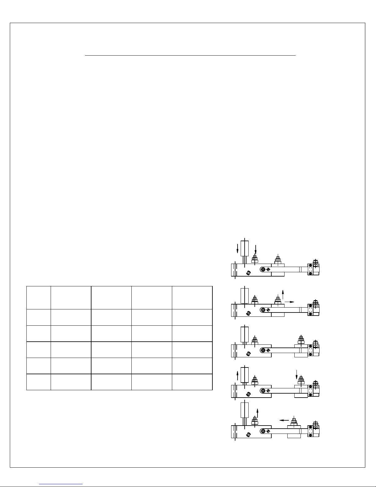
SETUP: With air off, insert stock between the stock guide rollers and
then pass the stock under the feed clamp. Lift the stock clamp
and push the stock through to the starting position. Turn air
on, install safety guards, your feed is now ready for operation.
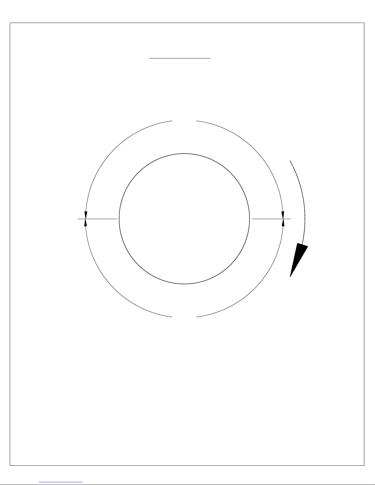
SPEED ADJUSTMENT: The speed adjusting screw on all Rapid-Air feeds
adjusts the forward speed of the slide block when feeding stock
into a die. High accuracy under special conditions can thus be
maintained by eliminating inertial slippage caused by oily or
heavy stock. The speed adjusting screw is located on the top
of the main body, opposite the actuating valve. Adjust for slower
speeds by turning the screw clockwise. Rapid-Air feeds are
shipped with the speed adjusting screw set to provide the best
operating conditions for the majority of applications.
4

5
INSTALLATION & OPERATING INSTRUCTIONS
Safety requirements: The use of a safety guard is recommended to
prevent operator injury. Rapid-Air manufactures safety guards
for all Rapid-Air model air feeds. When using an electric valve,
a safety switch is recommended for the operator to disconnect
power when servicing equipment. The use of a 3 way shut-off
valve is required to be installed at the feed so the operator can
shut off air and purge the feed of air before servicing the feed
or press. A 2 way valve is not sufficient as it will only shut off air
and not release the air in the feed. A quick disconnect coupling
should also be used behind the shut-off valve for easy removal
of the feed from the press. Make certain the slide block is forward
(at main body) before turning air on. If an electric valve or an
electrical circuit is used on or with the feed, it must be wired
through the safety disconnects of the press it is used on. The
feed should always be controlled by the press.
STEP
ACTUATING
VALVE
STATUS
STOCK
CLAMP
STATUS
FEED
CLAMP
STATUS
SLIDE
BLOCK
STATUS
1
2
3
4
5
STARTS
DOWN
DOWN
DOWN
STARTS
UP
UP
CLOSES
CLOSED
CLOSED
CLOSED
OPEN
CLOSED
OPEN
OPEN
CLOSES
CLOSED
FORWARD
STARTS
RETRACTING
RETRACTED
RETRACTED
FEEDING
*
*
*TEMPORARILY
AIR FEED OPERATING SEQUENCE STEP 1
STEP 2
STEP 3
STEP 4
STEP 5

6
FEED ACTUATION
BOLSTER PLATE
DIE
RAM
CUSTOMER SUPPLIED
ACTUATING PLUNGER
RAPID-AIR FEED
WITH MANUAL ACTUATING VALVE
WITH ELECTRIC ACTUATING VALVE
ELECTRIC VALVE TO BE
LOCATED AS CLOSE TO
FEED AS POSSIBLE
DIE
BOLSTER PLATE
RAPID-AIR FEED
RAM
REFER TO PAGE 8
FOR PLUMBING SCHEMATIC
ADJUSTABLE
CAUTION! OVER TRAVEL
WILL DAMAGE FEED
( SEE PAGE 3 FOR SETUP )

7
TIMING
Your Rapid-Air feeder must be timed to the crankshaft rotation of
the press. It is recommended that you allow 180° rotation of the
press crankshaft for the feeding of material. See diagram below.
180°
180°
CRANKSHAFT
1
2
3
4
M
A
T
E
R
I
A
L
F
E
E
D
C
Y
C
L
E
M
A
T
E
R
I
A
L
W
O
R
K
I
N
G
C
Y
C
L
E
POSITION #1
POSITION #2
POSITION #3
POSITION #4
PRESS CRANKSHAFT TOP DEAD CENTER
END MATERIAL FEED CYCLE
PRESS CRANKSHAFT BOTTOM DEAD CENTER
START MATERIAL FEED CYCLE
C
R
A
N
K
S
H
A
F
T
R
O
T
A
T
I
O
N

8
ELECTRIC VALVE SCHEMATIC
(A & B FEEDS)
(C, D, W, F, H, FX, L, & LX FEEDS)
#2
CYLINDER
MAIN AIR
IN
#3
INLET
DEENERGIZED
ENERGIZED
SOLENOID VALVE
PLUMBED AS NORMALLY
OPEN (VALVE NOT
ENERGIZED)
#1
EXHAUST
#3
IN
#2
CYL.
#1
EXH.
#3
IN
AIR 75-125 PSI
LINE VOLTAGE
ROTARY CAM TO
ENERGIZE/DEENERGIZE
SOLENOID VALVE
(switch actuated at bottom
of press stroke. feed retracts
when circuit is closed)
STROKE
SOLENOID VALVE
N.O. (DEENERGIZED)
NORMAL "HOME" POSITION
STROKE
SOLENOID VALVE
CLOSED (ENERGIZED)
IN
OUT
EXH.
FROM FEED
TO VALVE (port #2)
FEED MODELS L, FX, LX
HAVE ADDITIONAL QUICK
EXHAUST PLUMBED BEFORE
VALVE

9
TROUBLESHOOTING
1. Feed and stock clamps work, but slide block does not move when
actuating valve is depressed.
a. Pilot operated valve (item #39) is stuck, either by grit,
swollen nylon or swollen "O"rings.
2. Excessive leakage of air from exhaust hole beneath speed adjusting
screw when actuating valve is in up position.
a. Poppet (item #40) not seating on bottom of cartridge
hole - check for grit or chips
Note: Refer to Rapid-Air exploded parts drawing of
Air Feeds to identify item numbers listed below
b. Leaking "O" rings #84, #85, #88, #90, #100 and #103,
check for wear.
3. Excessive leakage of air from exhaust hole, also sluggish
operation of feed clamp pistons with actuating valve in up position.
a. Leaking of "O"rings #85 & #90, check for wear.
4. Excessive leakage of air from exhaust hole when actuating valve
is in down position. (Note:a slight amount of air leakage is normal
in this position.)
a. Tight "O" rings or grit around pilot operated valve
(item #39) may prevent it from moving it's full stroke.
b. Worn poppet (item #40).
c. Poppet (item #40) is install backwards.
5. Stock clamp does not move up and down when actuating valve is
depressed. Other operations appear normal.
a. Worn "O"ring (item #96) around O.D. of stock clamp
pistons.
6. Excessive leakage of air from actuating valve vent hole when actuating
valve is in the up position.
a. "O" ring (item #103) beneath actuating valve retainer
(item #31c) is leaking. Install "O"ring beneath retainer,
not in air groove.

10
TROUBLESHOOTING
7. Gradually reduced speed.
a. Lack of oil.
b. Low viscosity oil.
c. Speed adjusting screw (item #67) turned in too far.
d. Oversized poppet (item #40).
8. Excessive leakage of air from pilot operated valve vent hole on
side of feed.
a. Leaking of "O"rings items #100, #101 or #102.
9. Cushion pistons (item #34) act too slow and provide too much
cushion.
a. Excessive oil , reduce supply.
10. Mist of oil coming from exhaust hole.
a. Excessive oil , reduce supply.
11. Feed has difficulty pushing last part of progression.
a. Feed is not in line with die. A slight angular adjustment
of the feed will reduce the binding of the stock on the
die, guides.
12. Under feeding.
a. Insufficient air pressure.
b. Feed is not in line with die.
c. Stock and feed clamps are loose.
d. Feed is not lubricated.
e. Stock excessively dirty - dirt maybe present between
slide block and main body.
f. Feed may be feeding before punches are clear from
stock or die. Adjust amount of depression of actuating
g. Feed may be operating too slow. Turn speed adjusting
screw counter-clockwise to increase speed.
h. Cambered stock. Use special stock clamp.
i. Interference of feed clamp pistons not allowing sufficient
clamp pressure.
valve.

11
TROUBLESHOOTING
13. Over feeding.
a. Stock is excessively dirty or oily.
b. Feed is operating too fast. Turn speed adjusting screw
clockwise to slow feed down.
c. Stock has large slitting burr. Check clearance between
clamps and stock.
d. Stock and feed clamps may be loose.
14. Slide block will move out but will not return without hesitation.
a. Check speed adjusting screw (item #67).
b. Check pilot operated valve (item #39). Swollen "O" ring
could be binding, until pressure build up breaks it free.
Check poppet (item #40).
15. Feed acts sluggish on start up, acts fine after running for a while.
a. Check pilot operated valve (item #39) for "O"ring binding.
Valve should move freely in cartridge (item #32)
Section through cartridge in Rapid-Air feed
39
PILOT
OPERATED
VALVE 40
POPPET
32 CARTRIDGE

12
A & B SERIES EXPLODED PARTS DRAWING

13
C, D, W, F, H, FX, L, P & LX SERIES EXPLODED PARTS DRAWING
This manual suits for next models
10
Table of contents