INASI
"V TECHNICAL DATA
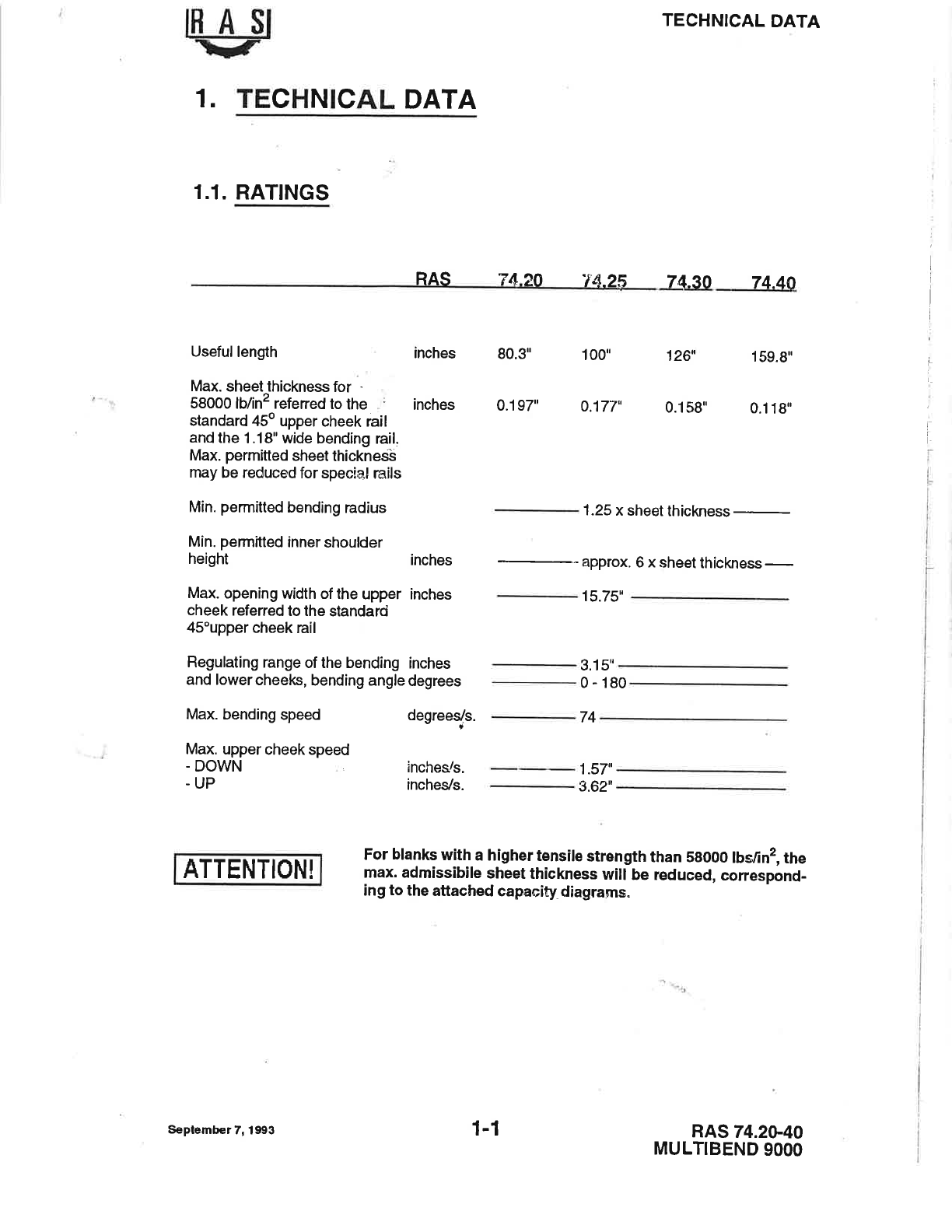
1. TECHNICAL DATA
1.1. RATINGS
RAS v4_20 "f4.25 7t1.30 74.40
i
I
I
I
I
l
:
l
1
i
I
Usefullength
Max. sheet thickness for -
58000 lb/in2 refened to the inches
standard 45o upper cheek rail
and the 1.18" wide bending rail.
Max. permitted sheet thicknesb
may be reduced for special rails
Min. permitted bending radius
Min. permitled inner shoulder
height
Max. opening width of the upper inches
cheek referred to the standard
45"upper cheek rail
Regulating range of the bending inches
and lower cheeks, bending angle degrees
Max. bending speed degrees/s.
Max. uppercheekspeed
- DOWN
.UP
ATTENTION!
inches 80.3" 1 00" 126" 159.9"
0.197" 0.177. 0.159" 0.1 19"
1.25 x sheet thickn
inches approx. 6 x sheet thiskngss -
inches/s.
inches/s.
15.75"
3.1str _
0-180
74_
1.57il _
3.62il _
For blanks with a higher tensile strength than 59000 lbsfin2, the
max. admissibile sheet thickness will be reduced, correspond-
ing to the attached capacity diagranns.
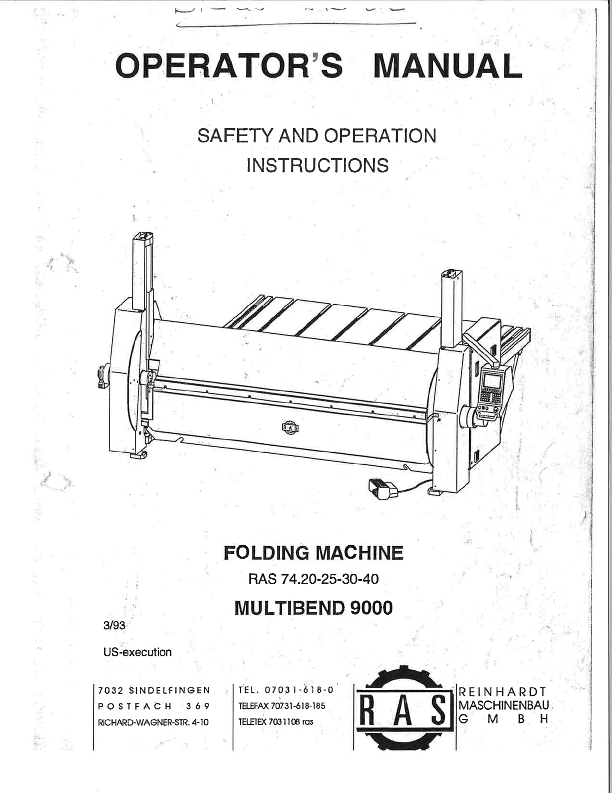
RAS 74.2G40
MULTIBEND 9OOO
September 7, 19!13 1-l