RATHI Gear-Flex RGD User manual

INSTALLATION & OPERATION MANUAL
FOR
TYPE - RGD / RGS
RATHI TRANSPOWER PVT. LTD.,
Gaia Apex, S.No.33/2D, Viman Nagar,
PUNE – 411 014 (INDIA)

GEAR-FLEX COUPLING
RE-OM-G-04/00-05/15 Page 2
TABLE OF CONTENTS
SR. No. Topics Page No
Product details
1 Notes 3
2 Technical Data 5
3 Marking Details 8
4 Installation 9
5 Start-Up and Operations 14
6 Failures - Causes and Remedies 16
7 Maintenance and Repair 18
8 Storage 18
9 Coupling Spare Components 19
10 Declaration : ATEX 20

GEAR-FLEX COUPLING
RE-OM-G-04/00-05/15 Page 3
1. NOTES
1.1 GENERAL INSTRUCTIONS
Please read the assembly instructions carefully before starting to operate the coupling. Pay
particular attention to the safety instructions.
The GEAR-FLEX coupling is approved for use in hazardous areas, if marked with CE
mark.
When using the coupling in potentially hazardous areas, pay special attention to the
safety instructions.
The assembly instructions are part of your product, and should be available with
maintenance personnel at all times until it is assembled.
Keep these instructions in a safe place, so they can be referred to by maintenance
personnel.
1.2 SAFETY AND ADVICE INSTRUCTIONS
Danger! Danger of injury to persons.
Caution! Damages on the machine possible.
Attention! Pointing to important items.
Caution! Hints concerning explosion protection.
1.3 GENERAL INSTRUCTIONS OF DANGER
Danger!
With assembly, operation and maintenance of the coupling make sure that the entire drive
train is protected against unintentional engagement. Serious injuries can occur from
rotating parts. Likewise, make sure to read through and observe the following safety
instructions:
•
All operations on and with the coupling must be performed with “safety first” being the
primary consideration.
•Make sure to disengage the power supply before you perform your work.
•Protect the power supply against unintentional engagement, for example, by providing
hints at the place of engagement, or removing the power supply fuse.

GEAR-FLEX COUPLING
RE-OM-G-04/00-05/15 Page 4
•Do not touch the coupling’s working area while it is operating.
•Protect the coupling against unintentional touch. Provide the necessary protective
covers and devices.
1.4 PROPER USE
Assembly, operation and maintenance work may be performed on the coupling only if:
• The assembly instructions are read carefully and understood.
• The personnel are technically qualified, & are authorized to do so by the company.
The coupling shall only be used in accordance with the technical data.
Unauthorized modifications to the coupling are not admissible. We decline any warranty due to
consequent damage. For future development of the product, we reserve the right to make
technical modifications.
The GEAR-FLEX coupling described here corresponds to the technical status at the time of
printing these assembly instructions.
1.5 INTENDED USE OF THE COUPLING
The intended use of the coupling is to connect input and output of a power transmission drive
with each other, in most cases these are two shafts. For Stationary Application Additional
equipment like brake drums, torque limiter, etc. can be added to the couplings and will not
change the intended use.
The coupling compensates within the technical limits misalignment and dampens shock loads or
vibrations.
MANUFACTURER’S DECLARATION IN CONFORMANCE TO EC MACHINE DIRECTIVE
2006/42/EC
Rathi Gear-Flex Couplings must be treated as components in the sense of the EC machine
directive 2006/42/EC.
Therefore M/s Rathi need not issue a separate declaration of conformity.
Information for safe use, installation, start up and operation can be found in this manual.

GEAR-FLEX COUPLING
RE-OM-G-04/00-05/15 Page 5
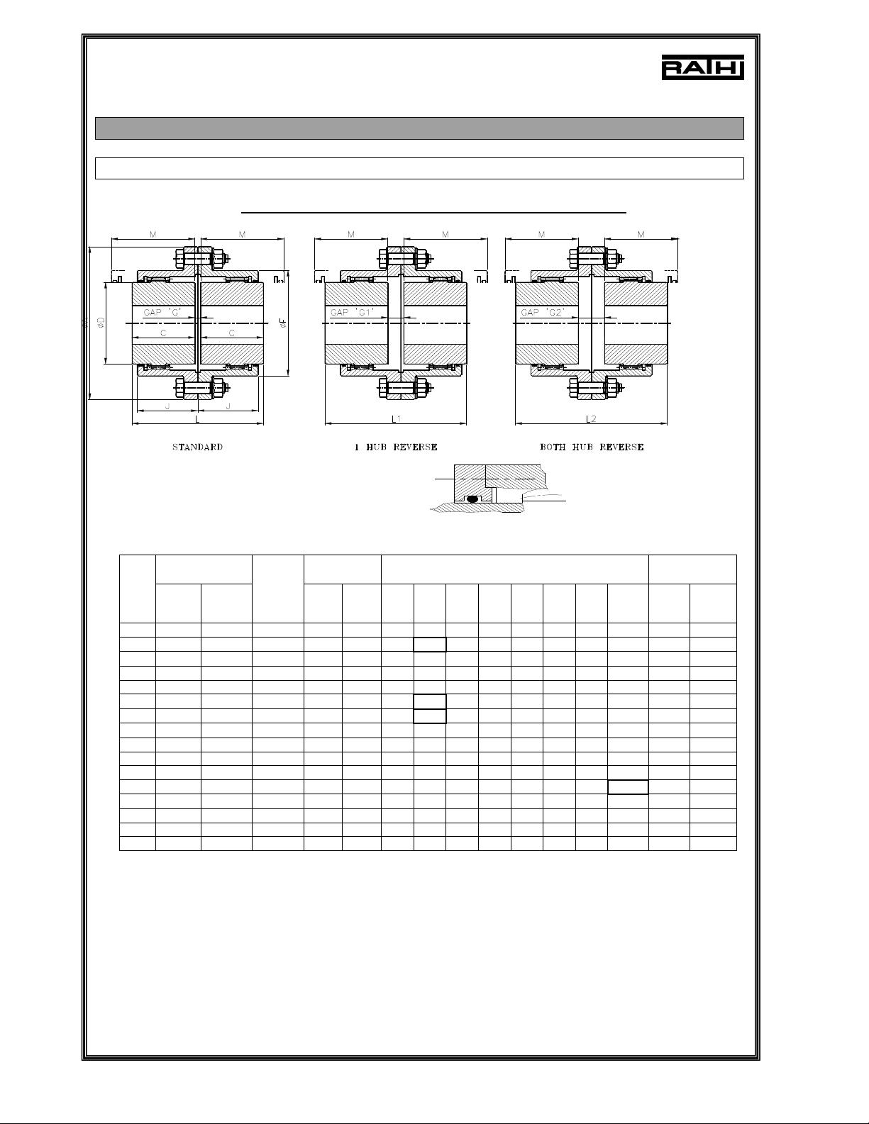
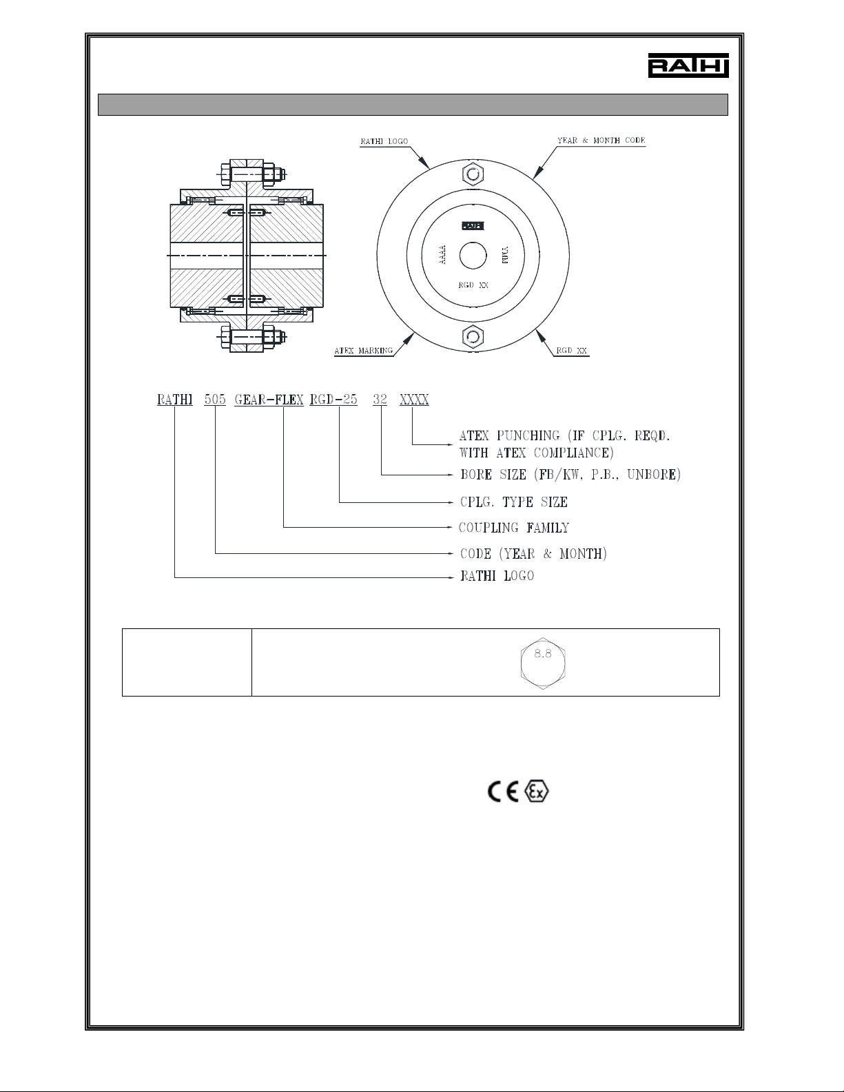
2. TECHNICAL DATA
2.1 DIMENSIONS, SPEED & WEIGHTS
Double Engagement Couplings: TYPE-RGD
THIS END COVER PLATE CONSTRUCTION FOR SIZE RGD-80 ONWARDS.
Coupling
Rating
Bore Dia
mm Dimensions in mm Solid Hub
Siz
e kW at
100
RPM
Rated
Torque
Nm
Max.
Speed
RPM Min.
Bore
Max.
Bore ØA L C ØD ØF J M GAP Mas
s Kg
WR²
Inertia
Kg m²
10 14 1337 8000 14 52 116 89 43 69 84 39 51 3 4.4 0.0052
15 30 2865 6500 22 65 152 103 50 86 105 48 61 3 9 0.0192
20 53 5061 5600 27 80 178 127 62 105 127 60 76 3 15 0.041
25 105 10027 5000 32 98 213 159 77 131 155 72 92 5 27 0.105
30 168 16043 4400 42 115 240 187 91 152 181 84 106 5 40 0.195
35 231 22059 3900 47 135 279 220 107 178 211 98 130 6 65 0.454
40 336 32086 3600 47 160 318 248 121 210 250 111 145 6 96 0.86
45 472 45073 3200 52 180 346 278 135 235 274 123 165 8 131 1.39
50 650 62070 2900 72 195 389 314 153 254 306 141 183 8 186 2.53
55 880 84034 2650 72 215 425 344 168 279 334 158 203 8 247 3.83
60 1205 115069 2450 77 235 457 384 188 305 366 169 228 8 299 5.21
70 1823 174084 2150 92 280 527 451 221 356 425 196 266 9 473 11
80 2639 252006 1750 95 285 590 508 249 385 485 243 300 10 682 20.72
90 3037 290012 1550 100 300 660 565 276 420 535 265 325 13 898 34.95
100 4100 391521 1450 120 330 711 623 305 470 595 294 355 13 1242 55.95
110 5300 506.1 1330 130 370 775 683 335 521 653 322 386 13 1608 86.14
NOTES:-
1. All dimensions in mm.
2. The outer dimensions of flanges are rounded up to nearest figure in above table.
3. For special versions contact M/s RATHI.
4. Couplings generally used up to 120°C. Can be used for higher temperatures by using proper grade of grease.
5. Weight & M.I. specified are with solid hubs.
6. Max. bore with key way as per DIN 6885/1.
7. ‘M’ minimum clearance required for aligning.

GEAR-FLEX COUPLING
RE-OM-G-04/00-05/15 Page 6
Single Engagement Couplings: TYPE-RGS
THIS END COVER PLATE CONSTRUCTION FOR SIZE RGS-80 ONWARDS.
Coupling
Rating
Min. Bore Dia
mm Max. Bore Dia mm DIMENSIONS
In mm
Size kW
at
100
RPM
Rated
Torque
kNm
Max.
Speed
RPM Flex
Hub
Rigid
Hub
Flex
Hub
Rigid
Hub ØA L C ØD ØF ØF1 J H
10 14 1337 8000 14 18 52 60 116 83 43 69 84 84 39 40
15 30 2865 6500 22 26 65 80 152 97 50 86 105 107 48 47.0000
20 53 5061 5600 27 30 80 90 178 121 62 105 127 130 60 59.000
25 105 10027 5000 32 37 98 110 213 151 77 131 155 157 72 74.000
30 168 16043 4400 42 44 115 130 240 179 91 152 181 182 84 88.000
35 231 22059 3900 47 52 135 150 279 209 107 178 211 212 98 102.000
40 336 32086 3600 47 52 160 180 318 237 121 210 246 250 111 116.00
45 472 45073 3200 52 57 180 200 346 266 135 235 274 276 123 131.00
50 650 62070 2900 72 77 195 220 389 301 153 254 306 309 141 148.00
55 880 84034 2650 72 77 215 240 425 341 168 279 334 334 158 173.00
60 1205 115069 2450 77 82 235 260 457 374 188 305 366 366 169 186.00
70 1823 174084 2150 92 102 280 300 527 439 221 356 425 425 196 218
80 2639 252006 1750 95 105 285 335 590 498 249 385 485 470 243 249.00
90 3037 290012 1550 100 - 300 370 660 552 276 420 535 518 265 276.00
100 4100 391521 1450 120 - 330 405 711 610 305 470 595 572 294 305.00
110 5300 506 1330 130 - 370 440 775 686 335 521 653 620 322 335.00
NOTES:-
1. All dimensions in mm.
2. The outer dimensions of flanges are rounded up to nearest figure in above table.
3. For special versions contact M/s RATHI.
4. Couplings generally used up to 120°C. Can be used for higher temperatures by using proper grade of grease.
5. Weight & M.I. specified are with solid hubs.
6. Max. bore with key way as per DIN 6885/1.
7. ‘M’ minimum clearance required for aligning.

GEAR-FLEX COUPLING
RE-OM-G-04/00-05/15 Page 7
2.2 PRODUCT VARIANTS
Coupling with Brake Drum
Coupling with Brake D
isc
Coupling with
Shear Pin
Coupling with
Spacer
Coupling with Floating Shaft Coupling with Vertical Mounting

GEAR-FLEX COUPLING
RE-OM-G-04/00-05/15 Page 8
3. MARKING DETAILS
e.g. (ATEX Punching)
RATHI GEAR-FLEX 505 RGD-25 32 II 2GD -30°C+120ºC
e.g. (Standard Punching)
RATHI RGD-25 32 505
Bolts
Marking of Grade 8.8 on bolt head,

GEAR-FLEX COUPLING
RE-OM-G-04/00-05/15 Page 9
4. INSTALLATION INSTRUCTIONS
4.1 BEFORE INSTALLATION
•Remove the coupling from packing & thoroughly inspect for signs of
damage.
•Disassemble the coupling by removing nuts & bolts. Clean all the
parts carefully.
•Remove protective coatings / lubricants from bores & keyways.
•If received in damaged condition, coupling should not be installed.
4.2 FINISH BORE & KEYWAY PROCEDURE
Danger!
Coupling supplied with CE mark- it is responsibility and liability of the customer
for marking correct F/B, K/W as specified by!
The maximum finish bore value (See Page No.-5 & 6 technical data) must not be
exceeded. In the event of failure to keep to these values, the hub may break and
the particles dispersed by the rotation may cause serious danger.
1. Rathi couplings are supplied with pilot bore unless ordered for finish bore. They
should be bored to required finish bore sizes with reference of the outside
diameter (OD) of hub (Refer fig. A)
2. Clamp the hub puller hole side dia. on lathe and true the hub O.D. Maintain
concentricity of finish bore w.r.t. coupling OD and face run-out within 0.04 mm for
dia. 10-180, 0.06 mm for dia. 180-400 & 0.08 mm for dia. 400-630.
3. Unless otherwise specified, std. tolerance of H7 for Finish bore and for keyway
width will be supplied as per DIN 6885/1.
4. Use dial bore gauge or plug gauge for respective bore size. (If plug gauge is used
then ensure that Go end of gauge will pass straight way through out bore length.)
5. Make chamfer of required size on both the sides of bore.
.
FIG. A

GEAR-FLEX COUPLING
RE-OM-G-04/00-05/15 Page 10
4.3 MOUNTING PROCEDURE
1. Slide the sleeves with internal teeth with rubber O ring on shafts before mounting
the hubs.
2. Mount the hubs with external teeth on their respective shafts flush with the faces of
hubs as shown in Fig. 1
3. With one machine firmly bolted down, set the equipments at a distance ‘G’ (refer
table A & B on page 12 & 13 resp.) between shaft ends by using a spacer bar equal in
thickness to the required gap ‘G’ as shown in Fig. 2.
Deviation in standard DBSE is defined as axial misalignment (end float). For normal
applications the shaft end should be flush with inner face of the hub. In some special
cases the shaft ends may protrude beyond the inner face of the hub or may remain
inside, if required. The distance between two faces of hubs is to be maintained as
specified. The variation in this distance should not exceed the permissible initial axial
misalignment given in table A on page 12.
Fig. 1
Fig. 2

GEAR-FLEX COUPLING
RE-OM-G-04/00-05/15 Page 11
4.4 ALIGNMENT PROCEDURE
Alignment procedure is given separately for each type of alignment, for simplicity.
However all 3 types of misalignments may be present at the same time.
For Permissible INITIAL (INSTALLATION) misalignments refer table A on page 12
For Permissible MAXIMUM (OPERATIONAL) misalignments refer table B on page 13
4.4.1 CHECKING PARALLEL / RADIAL ALIGNMENT
Check the parallel/Radial alignment with the help of straight edge resting squarely on
both the hubs at 4 places 90°apart. The deviation in the readings should not exceed
the permissible initial parallel misalignment mentioned in table A.
(Refer Fig. 3)
4.4.2 CHECKING ANGULAR ALIGNMENT
Check the angular misalignment with the help of slip gauges by inserting in the gap at
4 places 90°apart.
The difference in max. & min. gap will be the Total Indicated
Reading (TIR).
The angular misalignment ‘X’ in mm is half the Total Indicated
Reading. The values of angular misalignment should not exceed permissible initial
misalignments mentioned in table A. (Refer Fig. 4).
Fig. 3
Fig. 4

GEAR-FLEX COUPLING
RE-OM-G-04/00-05/15 Page 12
4.5 ASSEMBLY PROCEDURE
1. Insert the gasket between the sleeve flanges. Position the
flanged sleeves with lubrication plugs.
2. Insert the bolts thru flange holes. Also place the washer &
nuts on bolts and tightening the bolts.
Remember: Assemble only with the help of the fasteners
supplied with the coupling.
3. Fill with recommended grease (RSG with reqd. qty.) for lubrication.
For grease quantity for respective coupling size, refer table No. C on page 14.
Use Loctite to prevent the loosening of threads, if required.
IMPORTANT:- The necessity for shields & guards varies with individual
installations. The owner or user must provide the required safety guards.
Safety guards or shields are not furnished by us with the couplings.
4.6 PERMISSIBLE INITIAL (INSTALLATION) MISALIGNMENTS
TABLE ‘A’
TYPE RGD TYPE RGS
ANGULAR ANGULAR
COUPLING
SIZE DEG./GEAR
MESH
‘X'
(mm)
PARALLEL
/RADIAL
'P' (mm)
AXAIL
(mm)
GAP
'G'
STD.
(mm)
DEG./GEAR
MESH
‘X'
(mm)
AXIAL
(mm)
GAP
'G'
STD.
(mm)
10 0.3 0.15 3 0.3 4
15 0.4 0.20 3 0.4 4
20 0.5 0.25 3 0.5 4
25 0.6 0.30 5 0.6 5
30 0.7 0.35
±
0.125
5 0.7
±
0.062
5
35 0.8 0.42 6 0.8 6
40 0.9 0.50 6 0.9 8
45 1 0.52 8 1.0 8
50 1.1 0.65 8 1.1 9
55 1.2 0.72
± 0.25
8 1.2
±
0.125
9
60 1.3 0.80 8 1.3 9.5
70 1.5 0.92 9 1.5 11
80 1.7 1.05 10 1.7 13
90 1.9 1.20
± 0.5
13 1.9
± 0.25
15
100
± 0.19º
2.1 1.38 ± 0.75 13
± 0.19º
2.1 ± 0.37 16
Fig. 5

GEAR-FLEX COUPLING
RE-OM-G-04/00-05/15 Page 13
4.7 PERMISSIBLE MAXIMUM (OPERATIONAL) MISALIGNMENTS
TABLE ‘B’
TYPE RGD TYPE RGS
ANGULAR ANGULAR
COUPLING
SIZE DEG./GEAR
MESH
‘X'
(mm)
PARALLEL
/RADIAL
'P' (mm)
AXIAL
(mm)
GAP
'G'
STD.
(mm)
DEG./GEAR
MESH
‘X'
(mm)
AXIAL
(mm)
GAP
'G'
STD.
(mm)
10 1.2 0.6 3 1.2 4
15 1.6 0.8 3 1.6 4
20 2 1 3 2 4
25 2.4 1.2 5 2.4 5
30 2.8 1.4
± 0.5
5 2.8
± 0.25
5
35 3.2 1.7 6 3.2 6
40 3.6 2 6 3.6 8
45 4 2.1 8 4 8
50 4.4 2.6 8 4.4 9
55 4.8 2.9
± 1
8 4.8
± 0.5
9
60 5.2 3.2 8 5.2 9.5
70 6 3.7 9 6 11
80 6.8 4.2 10 6.8 13
90 7.6 4.8
± 2
13 7.6
± 1
15
100
± 0.75º
8.4 5.5 ± 3 13
± 0.75º
8.4 ± 1.5 16
Half Flexible Gear Couplings Type RGS cannot accommodate parallel misalignment.
Gap ’G’ in the above table is given when angular & axial misalignments are zero.

GEAR-FLEX COUPLING
RE-OM-G-04/00-05/15 Page 14
5. START-UP AND OPERATIONS
Lubricants must never be mixed with other substances.
Before mixing different types of lubricants always ask the manufacturer on
the compatibility of the lubricants.
5.1 GREASE QUANTITY
TABLE ‘C’
GREASE QTY. (Kg)
Sr. No. COUPLING SIZE
RGD RGS
1 10 0.03 0.015
2 15 0.06 0.030
3 20 0.17 0.085
4 25 0.23 0.115
5 30 0.34 0.170
6 35 0.45 0.225
7 40 0.79 0.395
8 45 1.08 0.540
9 50 1.59 0.795
10 55 1.93 0.965
11 60 3.46 1.730
12 70 6.35 3.175
13 80 9.6 4.8
14 90 13.3 6.65
15 100 17.3 8.65
RECOMMENDED GREASE – RATHI SPECIAL GREASE (RSG) , EXXON MOBIL EP2 ,
ESSO - HMP , BEACON 2 OR 3, SHELL (δg = 910 Kg/m3)
If the grease quantity filled is not in accordance with the specified quantity,
the coupling may become an explosion hazard.
5.2 PROCEDURE BEFORE START-UP
Bolt tightening torques for the coupling and tightening torques for the
foundation bolts of the coupled machine must be checked before
startup. Enclosures (coupling protection, contact guard) must be fitted.
Overload conditions during startup cannot be excluded. If the
coupling breaks through overload, metal parts may fly off and cause
personal injury and/or material damage.

GEAR-FLEX COUPLING
RE-OM-G-04/00-05/15 Page 15
5.2.1 BOLT TIGHTENING TORQUE
TABLE ‘D’
Sr.
No.
COUPLING SIZE
(RGD/RGS)
BOLT
TIGHTENING
TORQUE Nm
1 10 6
2 15 21
3 20 50
4 25 97
5 30 97
6 35 167
7 40 167
8 45 167
9 50 265
10 55 265
11 60 265
12 70 396
13 80 334
14 90 653
15 100 653
If the coupling is to be used below ground in potentially explosive
areas, the coupling, which is made of steel, must be provided with a
robust casing to avoid the risk of ignition from e.g. friction, impact or
friction sparks.
The depositing of heavy metal oxides (rust) on the coupling must
be avoided by the casing or other suitable precautions.

GEAR-FLEX COUPLING
RE-OM-G-04/00-05/15 Page 16
6. FAILURES - CAUSES AND REMEDIES
6.1 INSTRUCTIONS TO USE IN Ex HAZARDOUS AREAS
General
The following irregularities can serve as a guide for fault tracing.
Where the system is a complex one, all the other component units must be
included when tracing faults.
The coupling must run with little noise and without vibration in all operating
phases. Irregular behaviour must be treated as a fault requiring immediate
remedy. In case of fault the drive must be stopped at once. The necessary
measures for repair must be taken in accordance with the safety regulations.
Caution!
RATHI will not be bound by the terms of the guarantee or otherwise be
responsible in cases of improper use of the coupling, modifications carried out
Without RATHI’s agreement or use of spare parts not supplied by RATHI.
Danger!
When correcting the faults and malfunctions, the coupling must always be taken
out of service. Secure the drive unit to prevent it from being started up
unintentionally. Attach a warning notice to the start switch.

GEAR-FLEX COUPLING
RE-OM-G-04/00-05/15 Page 17
6.2 FAILURE MODES AND FAULT DIAGNOSIS
(*) - Consult M/s RATHI if required
SR.
NO.
FAILURE MODE PROBABLE CAUSES CORRECTIVE ACTIONS
1
Worn out Gear teeth
Shaft bearing failure
Excessive
misalignments.
Replace the coupling
Realign the coupling
2 Premature wear of Gear
Teeth
Excessive starts and
stops
High peak load
Use coupling with heat
treatment on teeth
3 Noise during running No lubrication Refill the grease upto
required limit
4 Heat Generation
No lubrication
Poor lubrication
Refill the grease upto
required limit
Refer maintenance
guidelines for lubrication
frequency
5 Grease leakage Improper sealing Ensure proper sealing to
avoid grease leakage
6 Loose hubs on shaft with
sheared keys.
Torsional shock
overload
Find & eliminate causes
of overload.
7 Severe corrosion on
outer surface Chemical attack Apply anticorrosive
coating on coupling (*)

GEAR-FLEX COUPLING
RE-OM-G-04/00-05/15 Page 18
7. MAINTENANCE AND REPAIR
For grease lubricated couplings, ensure that the recommended quantity of
grease is applied on the coupling teeth (internal & external) to such an
amount that the teeth are completely covered. After tightening the coupling
sleeves, fill the coupling with specified amount of grease from the grease nipple by
the use of grease gun.
The level of grease should be checked at regular intervals of 6 months to ensure
correct levels. The first grease change should take place before 3 months in
operation. To exchange the grease for the first time (after 3 months), dismantle the
coupling and thoroughly clean away inside to remove used grease, abrasive powder
etc. After cleaning, reassemble the coupling and fill the required quantity of grease
again for lubrication.
It is recommended that grease to be renewed at 2 years interval. Remove entire
used grease by dismantling the coupling and refill the coupling with new grease.
Maintenance checks:
a. Check for vibration and noise
b. Check for leakage
c. Check for damages on gear teeth
d. Check for damages and deterioration of `O'-ring
e. Check for deterioration of grease.
Checks mentioned above in Sr. No. a & b can be made by observing from outside
after comparing with condition under normal operation. The other checks should be
carried out every six months by dismantling the coupling.
Damaged ‘O’ rings must be replaced.
In case of high ambient temperature, frequent overloaded condition,
frequent reverse operation, large parallel misalignment and angular
misalignment, ensure that the checking intervals are shortened.
Note:
Correct initial installation, accurate alignment, usage of right quantity and quality of
lubricant will ensure longer life and smooth/trouble free operation of the coupling.
8 STORAGE
All couplings are to be stored and handled in conditions free from compression, tension or other
deformation.
Attention is drawn to the need to keep the product away from heat or continual sunlight.
The coupling components are supplied in storable conditions and can be stored in a dry, covered
place for an indefinite time.

GEAR-FLEX COUPLING
RE-OM-G-04/00-05/15 Page 19
9. COUPLING SPARE COMPONENTS
(RGD/RGS)
COUPLING COMPONENTS
SR. NO.
TYPE PART NO COUPLING PARTS QTY
1 SLEEVE 1
2 HUB 1
3 BOLTS, NUTS AND WASHERS #
4 'O' RING 1
A
RGD FLEXIBLE GEAR
COUPLING
HALF
5 GASKET 1
6 RIGID HUB 1
5 GASKET 1
B RGS RIGID GEAR
COUPLING HALF 3 BOLTS, NUTS AND WASHERS #
#
- ONE FULL SET AS PER COUPLING SIZE
This manual suits for next models
1
Table of contents
Other RATHI Industrial Equipment manuals