SWL25 Room-Selector
Installation
KI-1200A
Panels
Rauland-Borg Corporation
l
3450 West Oakton Street, Skokie, Illinois 60076-2951
l
(847) 679-0900
GeneralInformation
The SW25 offers room selection only (no call-in signal).
Description
The SWL25 also provides a call-in signal. When a call
The SW25 and SWL25 panels are
used
with all Director@ is made from a switch in the classroom, an LED lights next
Series sound and communications systems. These panels to the corresponding number on the panel and a tone alerts
let you selectively connect up to 25 rooms to either the the console operator to the call. The LED lamp remains lit
program or the intercom channel. There is also a center until the operator answers the call, at which time the lamp
OFF
position. Color-coded directions identify each chan- automatically shuts off.
nel: green for program, and orange for intercom.
Installation
Cabling Requirements
i../
Systems using the SW25 (no call-in signal) require one
twisted pair in a shield for each speaker station. Systems
using the SWL25 (call-in signal) require one additional
conductor within the shielded cable for each speaker
station. Use #22-AWG solid or stranded conductors with
22-AWG drain wire. If you’re
using
insulation-piercing
connectors, the outside diameter of any wire, including its
insulation, must not exceed
0.095”.
Cable Routing and Strain Relief
Route the cables as shown in the diagram. Secure them
with three plastic cable ties through the guide loops in the
rear bracket. Leave service loops in the cables
used to
interconnect the equipment panels and at least a one-inch
slack in each cable. This permits reconnection when
required.
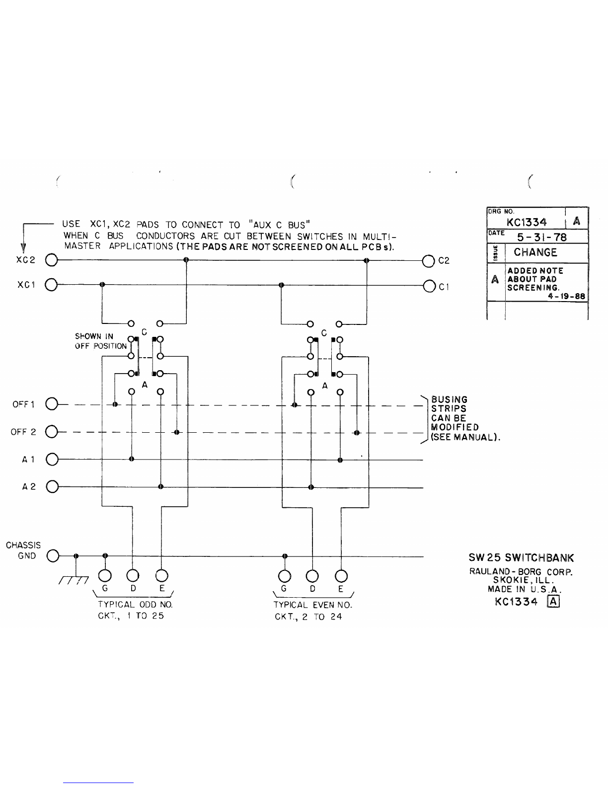
Connect the twisted pair to terminals D and
E,
and the
drain wire to terminal G for each line circuit. On Model
SWL25 only, connect the third conductor for calf-in to
terminal T(Trigger).
Connector or Bus Wiring
L,......./.
There are three terminals
(OFF, A, 0
at the ends of the
switchbank that will be interconnected in a factory-wired
system. These interconnections provide loop-through for
common functions, especially between multiple switch-
banks.
For wiring details, read the instruction manual for
the proper program and intercom equipment panel. When
you’re wiring to these end terminals, you may need to
cut
slots in the connector shells for loop-throughs between
switchbanks.
Recommended Terminations
Insulation-piercing connectors are the fastest, most re-
liable way to terminate wire to the switchbank. These
connectors must be ordered separately. Order one SK-2522
Connector Kit for each switchbank. The kit contains 25
four-terminal connectors for 22-AWG wire. The attached
manual, KI-1564, tells how to install these connectors.
Alternative Method #I
Modified wire wrapping may be used to terminate 22-
or 24-AWG solid conductors. Strip back wire about lb” and
use a wire-wrapping tool that provides one complete turn
of insulation around the terminal pin. This modified wire
wrap provides the required strain relief.
Alternative Method #2
Crimped connectors may be used where there is a
mixture of wire gauges (18-24 AWG) in the system, or
where preferred. Multiple-gauge crimped connectors and
an adapter shell are required for this termination method.
Order one CTA25 Terminal Adapter Kit for each switch-
bank in the system. The kit contains 25 four-terminal
adapter housings and 100 crimp connectors. Hand Tool
G2501 (or the older G317A) is required to crimp the
connectors onto the wires.
Strip away about 1‘I? of the cable sheathing and shield,
then strip the individual wires
about ‘kiP.
Crimp each
terminal onto a wire using Molex Model HTR-2445-A
91988 Rauland-borg Corporation . Printed in U.S.A. Page 1 of 4
Orig. lo/87 Rev. 4/88. 2d Printing 12/95.