Ravel RMC-PRS-56E-PUN User manual

Retractable Flap Barrier Operation Manual
2
- -
Dear Customer!
Thank you for choosing our Intelligent brushless Retractable Flap Barrier
RMC-PRS-56E-PUN. Please follow the instructions given in the Manual carefully,
and this quality product will provide many years of trouble-free use.
Assembly and Operation Manual (hereinafter-the Manual) for the Retractable
Flap Barrier contains data that is necessary for the most full use of operating
advantages of the turnstile as well as chapters on packaging, installation and
maintenance.
Only qualified personnel, following the instructions of this Manual, must carry out
installation and maintenance.
1. Introduction
The Retractable Flap turnstile was developed to be robust, reliable and esthetical
pleasing. Its rounded lines house a sturdy blocking mechanism designed for very
low maintenance. The equipment is provided with a standard electric interface and
is easily integrated into a system with write/read facilities, such as access control
system, time & attendance system, ESD system, fare collection system and
biometric system, etc.
The Retractable Flap turnstile is designed for managing pedestrian flows at
entrance points of industrial facilities, banks, administrative buildings, retail
outlets, railway terminals, airports providing free passageway in emergency
situations. To ensure fast and convenient passage it is recommended to install one
turnstile per 500 people working the same shift, and on the basis of maximum
working load 30 persons/min. See Chapter 4 for information on the throughput
capacity of the turnstile.
The Retractable Flap turnstile you purchased is researched and produced in
accordance with CE quality management system and is a product having gone
through strict and careful inspection.

Retractable Flap Barrier Operation Manual
3
- -
The product is equipped with sophisticated technology. To ensure a safe and
reliable operation and to ensure the safety operation, the operation manual is
provided with special precautions for the operation of the system. It is
recommended that the user read carefully the operation manual prior to application
of the equipment, otherwise, your right may be infringed due to an improper
application of the equipment.
This manual presents a detailed description of Retractable Flap turnstile operation
and components.
2. Warranty
The manufacturer guarantees that the turnstile complies with applicable statutory
safety and electromagnetic requirements provided that the instructions on storage,
installation and operation are observed.
The warranty period is 12 (twelve) months commencing from the date of sale. We
will repair or replace at our discretion any defective product, provided it is
returned to our factory. Please contact our service department before returning any
product.
3. Safety Precautions & Requirements
1. General Safety Notes
The Retractable Flap turnstile has been designed built and tested according to the
latest technology. Although it has left the factory in a fully operational and safe
condition, it is important that the installation is carried out correctly therefore the
operating instructions must be read carefully and the safety notes must be
observed.
Any liability and warranty is declined by the manufacturer in the case of incorrect
use and use for purposes other than intended.

Retractable Flap Barrier Operation Manual
4
- -
The electrical power used in this equipment is at a voltage high enough to
endanger life. Before carrying out maintenance or repair, you must ensure that the
equipment is isolated from the electrical supply and tests made to verify that the
isolation is complete.
Carefully read the instruction in this manual before assembling and installing the
Retractable Flap turnstile. This will extend the life of the product and will enable
you tofully benefit from all its features.
3.2 Safety Notes
◼Disconnect all external opening or closing devices (access control, control
desk, etc.) during maintenance work.
◼It is prohibited to install the Retractable Flap turnstile without proper
mounting tothe foundation.
◼Amainpower switch or residual current operateddevice is compulsory.
◼Before commissioning make sure all electrical and functional features are
tested
◼The electrical wiring of theRetractable Flapturnstile must comply with the
included drawings
◼Only certified and trained electrical technicians may perform the electrical
connections.
◼Only certifiedand trained electrical technicians may remove covers for mains
plug mains receivers or wiring.
◼During maintenance work the fixing bolt must be checked and tighten, if
necessary.
◼Current carrying components like switching power supply, solenoids,
resistors, stator housings of motors, lamps etc. shall not be touched while in
operating temperature condition; this can cause skin burns
◼During application of the product, it is forbidden to sit on or press with force
on the barrier rod, otherwise, unnecessary damage may be caused to the
Retractable Flap turnstile.
◼It is recommended to use correctly the equipment interface regarding tothe

Retractable Flap Barrier Operation Manual
5
- -
electric characteristic, otherwise, damage to the equipment and other
equipment of theuser may be resulted.
◼The equipment is not equipped with explosion-proof design, and it is not
allowed to apply the equipment to an environment with danger of
inflammable or explosion. However, it is optional for the user to purchase
products of other type for the purpose.
3.3 InstallationSafetyRequirements
The installation should be carried out by the qualified personnel after careful
study of thisManual.
Warning!
◼All thecables shouldbe connectedup when the power supply is switched off
from the ACmains.
◼Only serviceable tools should be used for installation.
◼Observegeneral electrical safetyrules when laying out thecables.
◼Before the turnstile first power on make sure its installation and connection
have been made accordingly.
3.4 Operation Safety Requirements
Observegeneral electrical safety rules when operating the turnstile.
Donotuse!
◼Do not use the turnstile under conditions that do not comply with the
requirements of Chapter 3 of this Manual.
◼Do not use the turnstile at supply voltage that does not comply with the
requirements of Chapter 4 of theManual.
Safety requirements on the power supply units operation are shown in their
certificates.

Retractable Flap Barrier Operation Manual
6
- -
4. Product Description
1. StandardFeature & Function Specifications
◼Fast identity authentication technology to accurately and efficiently identify
IC cards, ID cards, magneticcards or barcode cards.
◼DC brushless motor is maintenance-free and new digital positioning.
◼Mechanical infrared double anti-pinch; optional in online mode or offline
mode.
◼Witha variety of operating models and functions, it can be programmed to be
bi-directional access, or exitby sensors.
◼Real-time fault self-test and alarm prompts to ensure safe operation of the
system and easy maintenanceand use.
◼Bi-directional, reverse direction intrusion and bi-directional tailgating
functionality, to deny unauthorized access.
◼Barrier locked in closed position to prevent force intrusion, until a valid open
signal is received.
◼With automatic counting and counting function, the number of people can be
displayed, which is convenient for real-time inspection. The total number of
displays is over 90,000. (optional)
◼(Sound and light/voice optional) With anti-crash prompt function, beware of
illegal entry or non-standard access; Powerful online intelligent control mode
allows you to easily:
A)Setting of import and export work methods. Brushing the same card
multiple times allows multiple people to pass the special features to meet the
needs of special occasions.
B)Set whether the card has a memory mode; use the normally open mode or
the normally closed mode to effectivelyalleviate the flow of people.
C)With humanized timeout reset time setting function, infrared sensing
technology realizes real-time monitoring channel, safety protection and anti-
tailing.
◼Emergency or special situation processing mode; with standard input and

Retractable Flap Barrier Operation Manual
7
- -
output interfaces, which facilitates integration of the system with other
devices.
◼Remotecontrol and management is available.
◼Super combination ability, different styles, series channel products can be
combined without affectingsystemperformance.
◼Powerful system capacity expansion, new products can be added at anytime.
◼Remote control management: The state of the gate is operated remotely to
meetthespecial needs of users and fire safety requirements.
◼Powerful self-checking function: The device is in fault monitoring state at
any time. The error reporting function is friendly and the human-computer
interactionis convenient and quick to realize maintenance;
◼Good anti-collision function (when the gate is in the state of opening and
closing the door, when there is an object hit, the brake detects the object and
immediately stops moving and reverses back); the service life is up to 100-
200 million times.
◼Emergency-escape function: When power off, it will be opened the gates
automaticallyto meet the request of fire protection. Also the gates will open
by pressing the emergency button which can be remote-controlled whether
the power is on or not. (Optional).
◼Standard fire alarminput interface, requires N.C normally close contact.
◼The turnstile system can easily integrates with the 3rd party equipment with
read facilities, such as biometric reader, consumption system, ESD system
and access control systemetc.
◼The turnstile system can be hooked up with multiple reader equipments
together. Rapid identification technique, available to identify accurately and
efficientlythe magneticcard, bar codecard, ID/ICcard, fingerprint and
face detectionetc.
◼Operation model: Both directions can be set as controlled mode or freemode,
two or one direction can be controlled by switch- button or access controller.
◼Withnormally open & normally closed workingmode.
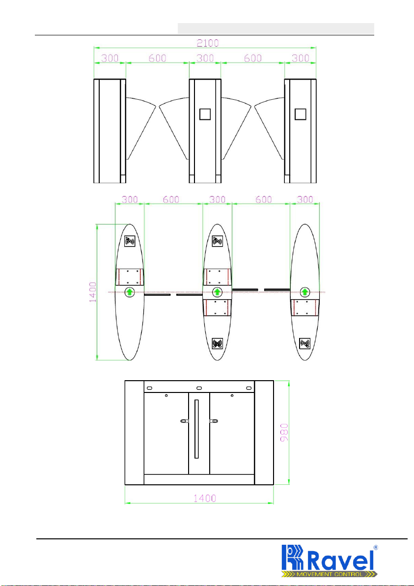
◼Passageway width at 1000mmavailable.

Retractable Flap Barrier Operation Manual
8
- -
4.2 Customized Features & Functions
◼AlternativeMaterials, Finishes and Custom Design
◼Usage Counter function
◼Remote-Controlled Button
◼Access Control,Biometrics System Integration
4.3 Specifications
◼Framework: 304# Stainless Steel (default),201# or 316# (optional)
◼Production process: full CNC laser cutting
◼Thickness of ply: 1.5mm(default)
◼Finish: stainless steel surface: brushed surface, polishingsurface
◼Dimension(L*W*H): L1400× W300 ×H980mm(default)
◼RetractableFlapmaterial:12mmAcrylic
◼RetractableFlap lane width: 600mm
◼Gate switching time: less than 0.4S
◼Passingspeed: normally open 50 people/ min; normally closed 30 people/
min
◼Communicationinterface: RS485
◼Input voltage: AC220; total power: less than200W
◼Communicationdistance: less than1200m
◼Signal input: dry contact signal or 12V levelsignal (effective signal is pulse
signal signal effective duration is large
Is equal to 50ms drive current minimum 10mA)
◼Relative temperature and humidity: Humidity is less than 95%, no
condensation. Temperature: -15 degrees to 80degrees
◼Working environment: indoor and outdoor (outdoor canopy)
◼Infrared standard 3 pairs.
◼The inductive card reader dimension: equipped with the standard mounting
brackets, or tailor.
◼Read facilities mounting: may be mountedon thesurface of turnstile gate, or

Retractable Flap Barrier Operation Manual
9
- -
flush mounted, or rack mounted. There is an output to interlock the read
facilities.
5 Equipment Definition
1. TermDefinition of Entry & Exit
(1)Entry: the direction waypassing through the barrier passage from outside the
control area and into the area controlled by theproduct.
(2)Exit: the direction way passing through the barrier passage frominside the
control area and going into the area outside the control of theproduct.
5.2 Equipment Operation Mode
The turnstile provides bi-directional access control. Each direction may be in one
of three states:
◼(1) Free passage: all person areauthorized to pass under all conditions
◼(2) Controlled access: each person must use a card reader before being
authorized to pass
◼(3) Lane closed: no persons are authorized to pass, and security cards are
ignored
5.3 EquipmentOutline Dimensions
Retractable Flap Barrier is witha complete set of types and specifications and can
be divided into types as given below. Fig. 1
Besides, there are also different types and specifications depending on different
read equipment installed.

Retractable Flap Barrier Operation Manual
10
- -
Fig. 1 The dimensions of Retractable Flap Barrier

Retractable Flap Barrier Operation Manual
11
- -
6. Equipment Assembly and Installation
Instruction
1. Installation Details
Caution!
Follow the safety requirements during the installation (see clause 3)
Correct turnstile installation provides its functionality and lifetime. Please
carefully study and followthe installationinstructions.
Caution!
The manufacturer shall not be liable for any damage caused as the result of
improper installation and declines any claims arising thereof in case if the
installation is not done in compliance with the instructions provided in this
Manual.
2. InstallationProcedure
(1)Prepare the tools for product installation and Sort out the auxiliaries in
accordance with the packing list;
(2)Determine the installation location in accordance with the system composition,
operation mode, application site, and prepare to install after carrying out the system
planning;
(3)As shown in Fig. 1 for the installation requirements, determine the installation
hole location, bury before hand at the installation location 4*M12 ground screw
bolts or 4*M12inflatablescrew bolts, As shown in Fig.2;
(4) Sheath the strong power and weak power cables respectively with 3/4”PVC

Retractable Flap Barrier Operation Manual
12
- -
tube, and bury them to the corresponding positions withconcrete;
(5) Moveeach cabinet to the respectiveinstallation position, and align with each
ground screwbolt;
Fig.2 Ground Foot Installation Foundation Diagram
Notes:
(1). AC220V power supply line pipe: use RVV3*1.0 power supplycable.
(6)Check the system composition and operation mode, and carry out the next
operation after confirming the above check;
(7)Open the cabinet door, select one of the products as a reference. (it is better to
select the middle one as reference). Align the hole for screw bolt at the chassis
withthe respective ground screwbolt. Then, tighten thenuts.
(8)Open an adjacent cabinet door. Align the hole for screw bolt at the chassis with
the respective ground screw bolt and arrange properly on line with the reference
product. Then, tighten the nut preliminarily. The rest products, if any, are installed
just the same;
(9)As shown in the connecting diagram of the system (Fig. 6, connect the power
line, control line to the connecting socket of the main controller board of the
turnstile, and connect properly the protection ground wire

Retractable Flap Barrier Operation Manual
12
- -
(10). After a certified check of status and function adjustment, fasten the ground
screw nuts.
6.3 Equipment composition and basic working principle
6. 3. 1 product structure
The product structure is mainly composed of two parts: mechanical system and
electronic control system;
6. 3 . 1 . 1 Mechanical systemstructure
The mechanical system is divided into two parts: the chassis and the movement.
As the carrier, the chassis is equipped with a reader/writer, a counter, a direction
knowledge device, an audible and visual alarm device, an infrared radiation
sensor, a door lock, etc.; the movement consists mainly of a motor, a reducer, a
frame, a driveshaft, a gate, and the like;
6. 3 . 1 . 2 Electronic control system
1) Electronic control system composition and function The electronic control
system is mainly composed of reader, main control board, infrared sensor,
direction indicator, counter, alarm
Devices, voice boards, limit switches, transformers, speakers, etc.; the main
components are as follows:
●
Reader: After reading the information on the card and after judging the
processing, it sends a gate signal tothe main control board;
●
Main and auxiliary control boards: the control center of the product, receiving
signals fromreaders and infrared sensors, and performingthese signals
After the logic and processing, the execution command is issued to the direction
indicator, motor, counter, and alarm.
●
Infrared radiation sensing: detecting pedestrian position and safety protection;
sensors at both ends of the channel determine the pedestrian passing
position,Safeguarding;
●
Permission indicator/channel indicator: displays the current transit status of the
channel, guiding pedestrians to pass through the channel safely and orderly;
●
Counter: records thenumber of people who effectively pass a certain channel

Retractable Flap Barrier Operation Manual
14
- -
fromthe samedirection;
●
Sound andlight alarmdevice: send an alarm prompt signal to illegal traffic
personnel;
●
Limit switch: the position at which the gate is controlled to rotate;
●
Voiceversion: make corresponding voice prompts according to theinstructions
issued by the main control board;
6. 3 . 2 Systemworkprinciple
1Turn on the power, display the board STAT(start), and then detect the electric
eye. First, the auxiliary machine control board cuts off the auxiliary machine's
infrared power supply (the auxiliary machine displays SENP). After the electric
eye detection is normal, the auxiliary machine turns on the infrared power supply
(the auxiliary machine displays SEHP). The host detects the normal electric eye.
Display SENO (sensor ok), if the electric eye is faulty, it will display E-SX (X is
the number of the problem electric eye). After the electric eye detection is normal,
enter the main and auxiliary machine communication detection normal display
SERO (serial ok), enter the gate reset digital after the communication is normal.
The tube displays RESU (RESUME) reset. If the reset time gate cannot be reset,
the display shows that RUNX (X is the current working mode of the gate, that is,
the value of LP02) is initialized after the E-CS is normal.
2After the pedestrian reads the legal card, the system sends a gate signal to the
main control board; the main control board receives the information of the reader
and the infrared sensor, and after comprehensive judgment processing, sends the
control signal to the direction indicator,the voice board and
The sub-control board, the control direction indicator changes from red to green,
the voice version makes corresponding voice prompts, and the sub-control board
does the phase
The auxiliary machine action should be in the normally closed mode, the gate is
opened (the gate does not operate when the mode is normally open), and
pedestrians are allowed to pass;
3) After the pedestrian passes the channel according to the direction indicator, the
infrared sensor detects the pedestrian passing through the channel and

Retractable Flap Barrier Operation Manual
15
- -
continuously sends a signal to the main control board until the pedestrian
completely passes the channel; the main control board sends a letter to the counter.
No., thecounter will automaticallyadd 1, completethe pass.
4)If the pedestrian reads the invalid card, the system prohibits pedestrians from
passing (normally open mode, the gate will be closed; normally closed mode,
gate)
No action;) and sound and light alarm or voice prompts, until the pedestrian exits
to cancel the alarm;
5) If the pedestrian forcibly brakes, the system will automatically lock the gate for
a few seconds and then automatically unlock and reset, if the pedestrian forcibly
pushes the door
If the gate exceeds a certain angle, the gate will be further locked until the
pedestrian exits to automatically unlock and reset (this function is only for
individual models)
PRECAUTIONS:
(1)The depth of the PVC tubes buried shall be more than 60mm. The height above
the ground shall be more than 50mm. And the exit of the PVC tube shall be bent
return so as to avoid the water falls in.
(2)All the operation above should be carried out under power off condition, and it
should be ensured that the protection ground wire of the system is connected
correctly, properly and firmly.
(3)In case the equipment selected is used outdoor, a concrete installation platform
of a size of 100mm~200mm should be prepared for humidity-proof at the location
for installation of the equipment. At the same time, rainproof facility such as sun
shading plate should be installed above the equipment. It is forbidden to use the
equipment directlyat an exposedenvironment.

Retractable Flap Barrier Operation Manual
16
- -
7. Debugging Introduce
Once the mechanical and electrical installation of the turnstile has been completed,
it can be put into service.
1. Checking the wiring connection
Please carefully check all wiring are correctly connected according to diagram,
check connectors are not loose; check if the equipment is well grounded. If
everythingis ok, then you can test the devices after power on.
please make sure the equipments are reliable grounded, unless you can’t do
debugging.
2. Function debugging
1. External entry opening signal and exit opening signal;
2.Without valid accesscontroller signal, acoustic signal for announcement of
unauthorised use. (extended voice prompt modular available).
3. Equipment Operation after poweron
Normally Closed model: turnstile arm will up automatically after power on, it will
drop automatically when power failure.
Normally Open model: barrier will open automatically after power on, and keep
normally open status.
---------------------------------------------------------------------------------------------------
Precautions:
(1) Please do not use the system when there is lightning, otherwise the
turnstile may be damaged.
(2) It is requiredto connect reliably the protection grounding of the system to

Retractable Flap Barrier Operation Manual
17
- -
avoid accident of personnelinjury.
8. Parameter setting of Main Controller Board
Example of menu settings:
Power on---R U N0---S E T---P0 0---I N C---L P 0 1---S E T---0 0 1 ---I N
C---0 0 2 ---S E T---LP 0 1---P 0 0 ---SE T---RU N0
Note : :
S E T key is functionkey
I N C is plus onekey
D E C is minus one key
The entrance and exit of the menu are P 0 0
This menu is a circular menu
The system runs the status code tube to display R U NX
X is the working mode of the system, that is, the value of L P 0 2
There arethree types of menus in this department : :
LXX for the logicmenu
dXX for the drive menu
N for the non-usermenu
Note: When exitingthe menu, themenu option willbe adjusted to P00. Press SET
to display RUNX and exitsuccessfully.

Retractable Flap Barrier Operation Manual
18
- -
1 Entering andexiting menu settings
The basic method for entering and exiting the menu while the system is running
(LED is shown as 'RUNX') is (button and display digital tube position Figure A-
1):
1) Press SET to enter the menu function setting status and display ‘P00’
2)Press the INC key to increase the system function number to the desired function
number (the system function number is incremented by 1 each time the INC key is
pressed)
3) Press SET to enter the parameter/function setting status.
4)Press the INC or DEC key to set the parameter (INC increments the parameter
value by 1, and decrements the parameter value by 1)
5)Press SET to save the setting value and return to the menu function setting
mode.
6) Press the DEC button to return the systemto P00
7)Press SET to exit the menu setting, enter the program running status, and
display the word 'RUNX'
Note: RUNX Xis the working mode of the device.
2 Menu function, setting
The following menus are unique to the main control board:
LP01: System workingstatus
Enter the menu setting item. When the display shows ‘LP01’, press SETto enter.
There are 2 operating states: 000: test mode; 001: Normally closedstate
LP02: Equipment working mode
●
When the display shows
‘
LP 0 2
’
, press SET to enter, and the following

Retractable Flap Barrier Operation Manual
19
- -
operation modes are available.
●
000:Two-way control of entry and exit, both access and exit are required to read
the card.
●
001: The entranceis controlled, the exit is free, the entrance needs to read the
card, and the exit can be accessed without reading the card;
●
002: The entry is controlled, the outboundis forbidden, theentrance needs to
read the card, and the exit prohibits pedestrians frompassing;
●
003: Incoming freedom, outbound control, no need to read cartoon lines at the
entrance, and need to read cartoon lines at the exit;
●
004: Freedomof entry,freedomof exit, entrance and exit can be accessed
without reading a card;
●
005: Incoming freedom, outbound is prohibited, the entrance does not need to
read the card, and the exit prohibits pedestrians frompassing;
●
006: The entry is prohibited, theexit is controlled, the entrance prohibits
pedestrians from passing, and the exit requires reading the card to pass;
●
007: Theentry is forbidden, the exit is free, the entrance prohibits pedestrians
frompassing, and the exit can be accessed without reading the card;
●
008: Incoming entry prohibition, outbound prohibition, channel cut-off, entrance
and exitto prevent pedestrians frompassing;
●
LP03: Incoming and outgoing to voiceprompt switching
●
The value is 0-2;
●
00: Forward traffic, forward voice prompt; outgoing traffic, outgoing voice
prompt;
●
01: The heading is out to thevoice prompt; the outbound direction is thevoice
prompt;

Retractable Flap Barrier Operation Manual
20
- -
●
02: Alarmfor thebuzzer.
LP04: default
LP05: default
LP06: Passtime
The value is 3-60, in seconds
LP07 : Signal effective time
The valueis 10-50 in seconds
LP08: deviceaddress
The value is 0-255;
LP09: extraordinary delay time
The value is 0-60;
The following menus have parameters for the main sub-control board:
dP01: maximumoperatingspeed of thegate
The valueis 0-16; the higher the value, the higher the startup speed;
dP02 : collision speed setting:
The value is 0-16; the larger the value, the greater the return strength;
dP03 : Retractable Flap Barriers zero is set: operate according to voice;
dP04 : Gate off 1 Fine adjustment
Refer to the slave control panel display (CLO1) when adjusting this parameter;
The value is 0-50;
dP05 : Gate off 2 Fine adjustment
Table of contents
Popular Turnstile manuals by other brands

Alvarado
Alvarado EDC Installation and maintenance instructions

Detex
Detex DSI ES9000 Installation and operation instruction

Alvarado
Alvarado WATCHMAN installation instructions

ZKTeco
ZKTeco FHT2300 user manual

BOON EDAM
BOON EDAM Trilock 50 Instruction card

Alvarado
Alvarado SUPERVISOR 5000 installation instructions