OZAK GLASS LINE A1 User manual

DD-75-193 R(0) Y.T.31.03.17
1
GL A1 & GL A2
INSTALLATION AND MAINTENANCE HANDBOOK
www.ozak-t.com
DD-75-193 R(0)
Y.T.31.03.17

DD-75-193 R(0) Y.T.31.03.17
2
INDEX
1. GENERAL INFORMATION .............................................................................................................................................. 3
1.1. Glass Line A1 Technical Specications
1.2. Glass Line A2 Technical Specications
2. SAFETY AND OPERATION .............................................................................................................................................. 7
2.1. Safety Warnings And Symbols
2.2. Power Supply Fuse Replacement
2.3. Safety Related Instructions
2.4. Operating Precautions
3. HANDLING AND INSTALLATION .................................................................................................................................... 8
3.1. Handling
3.2. Installation
4. SETUP AND OPERATION ................................................................................................................................................ 10
4.1. Power and Grounding Connections
4.2. Control Board Connections
4.3 Control Board Settings
4.3.1 Blocking Passage Direction
4.3.2 Timeout and Mode Settings by Dip Switch
4.4. Operating Instructions
5. POST INSTALLATION CHECK LIST .................................................................................................................................. 12
6. SERVICE AND MAINTENANCE ....................................................................................................................................... 13
6.1. Maintenance Instructions
6.1.1. Recomended User Maintenance
6.1.2. Periodic Maintenance by Technical Service Personnel
6.2. Trouble Shooting Guide
6.3. Motor Driver Adjustments
6.4. Photo Sensor Replacement and Alignment
6.5. Motor Replacement
6.6. Schematic Diagram
7. LIST OF REPLACEMENT PARTS ...................................................................................................................................... 19
8. CE DECLARATION OF CONFORMITY AND WARRANTY ................................................................................................ 20
8.1. Warranty Certicate
8.2. Warranty Terms and Conditions
8.3. Cases Excluded From The Coverage of Warranty
8.4. Declaration of CE Compliance
GLASS LINE A1
TECHNICAL SPECIFICATIONS
DD-72-147 R(16) 1 / 2 Y.T.04.04.2017
Power Requirements :110/220-240V. 60/50Hz. AC (%±10) 24V.DC at standby ~2W.max. ~65W. System is
powered by a well regulated SMPS which can automatically compensate for voltage fluctuations.
Dimensions : Cylindrical body 1030mm x Ø230mm x Wing width (550 / 900mm)
Body Features : 1mm thick, single piece, 304-Grade satin finished stainless steel cylindrical body.
Wing Features : Wing is made of 10 mm thick tempered glass (Opt.polycarbon or acrylic). 550 mm or
900 mm wing lengths are available as standard choices.
Top Lid Features : Standard 20mm thick natural granite (Star Galaxy Black) stone top lid for a decorative
and aesthetical appearance (opt. tempered glass, stainless steel, wood).
Indicator Features : Built-in circular RGB LED status indicators are located under the top lid. Illumination is
blue at stand-by; green during authorised passage, flashing red for unauthorised
attempts and green for emergency alert mode.
Operating Temperature, Humidity, IP Rating, MCBF
: -20°C - +68°C (Opt. -50°C with heater unit) / RH 95% non-condensing /IP 44 Indoor
Model (IP 56 is available for optional pipe wing versions)/ 1M Cycles.
Control System : All inputs are opto-coupler protected. Controlled by dry contact or grounding input.
Compatible with all access control systems that provide dry contact or grounding
outputs. Optional RS232/RS485/TCP IP control module is available.
Weight : ~58kg (with 90 cm. tempered glass wing and granite top cover).

DD-75-193 R(0) Y.T.31.03.17
3
GLASS LINE A1
TECHNICAL SPECIFICATIONS
DD-72-147 R(16) 1 / 2 Y.T.04.04.2017
Power Requirements :110/220-240V. 60/50Hz. AC (%±10) 24V.DC at standby ~2W.max. ~65W. System is
powered by a well regulated SMPS which can automatically compensate for voltage fluctuations.
Dimensions : Cylindrical body 1030mm x Ø230mm x Wing width (550 / 900mm)
Body Features : 1mm thick, single piece, 304-Grade satin finished stainless steel cylindrical body.
Wing Features : Wing is made of 10 mm thick tempered glass (Opt.polycarbon or acrylic). 550 mm or
900 mm wing lengths are available as standard choices.
Top Lid Features : Standard 20mm thick natural granite (Star Galaxy Black) stone top lid for a decorative
and aesthetical appearance (opt. tempered glass, stainless steel, wood).
Indicator Features : Built-in circular RGB LED status indicators are located under the top lid. Illumination is
blue at stand-by; green during authorised passage, flashing red for unauthorised
attempts and green for emergency alert mode.
Operating Temperature, Humidity, IP Rating, MCBF
: -20°C - +68°C (Opt. -50°C with heater unit) / RH 95% non-condensing /IP 44 Indoor
Model (IP 56 is available for optional pipe wing versions)/ 1M Cycles.
Control System : All inputs are opto-coupler protected. Controlled by dry contact or grounding input.
Compatible with all access control systems that provide dry contact or grounding
outputs. Optional RS232/RS485/TCP IP control module is available.
Weight : ~58kg (with 90 cm. tempered glass wing and granite top cover).

DD-75-193 R(0) Y.T.31.03.17
4
GLASS LINE A1
TECHNICAL SPECIFICATIONS
DD-72-147 R(16) 2 / 2 Y.T.04.04.2017
System Features & Operation
: Microprocessor controlled, bi-directional DC motor driven mechanism with torque and
speed adjustments. The system opens the wing in either direction upon receiving
contact to allow passage. Glass wing automatically retreats when it pushes against an
obstacle and goes into alarm after a second attempt.
Emergency Mode : In case of emergency input, the wing opens in either direction (pre-set direction by
internal dip-switch) and the system stays in open position until the emergency input is
removed.
Wing can be pushed open manually in either direction in case of a power failure.
Wing Speed : Wing speed is controlled by adjustable PWM controlled motor driver system.
For 900mm Passage Width Tempered Glass Wing:
-Wing Opening Speed: ~3,0 seconds by default, ~2,5 –3,5 sec. adjustable.
-Wing Closing Speed: ~3,0 seconds by default, ~2,5 –3,5 sec. adjustable.
For 550mm Passage Width Tempered Glass Wing:
-Wing Opening Speed: ~2,7 seconds by default, ~2,5 –3,5 sec. adjustable.
-Wing Closing Speed: ~2,7 seconds by default, ~2,5 –3,5 sec. adjustable.
90° movement from original position,
Standard Features : Natural granite top lid (Star Galaxy Black), RGB LED indicator.
Optional Accessory and Applications
: Remote control unit, interface unit for PC, RS485, RS232 and LAN, counter, audio-
messaging system, base plate, different top lids, separator, card reader pole.
*Design and specifications are subject to change without notice.
GL A2
TECHNICAL SPECIFICATIONS
1 / 2
Power Requirements : 110/220-240V. 60/50Hz. AC (%±10) 24V.DC at standby ~2W.max. ~65W. System
is powered by a well regulated SMPS which can automatically compensate for voltage fluctuations.
Dimensions : Cylindrical body 1500mm x Ø230mm x Wing width (900mm)
Body Features : 1mm thick, single piece, 304-Grade satin finished stainless steel cylindrical body.
Wing Features : Wing is made of 4,0+1,52+4,0 mm laminated & tempered 900 mm glass. Wing
length and 1500/1800 mm wing heights are available as standard choices.
Top Lid Features : Stainless steel or natural granite (Star Galaxy Black) stone top lid.

DD-75-193 R(0) Y.T.31.03.17
5
GLASS LINE A1
TECHNICAL SPECIFICATIONS
DD-72-147 R(16) 2 / 2 Y.T.04.04.2017
System Features & Operation
: Microprocessor controlled, bi-directional DC motor driven mechanism with torque and
speed adjustments. The system opens the wing in either direction upon receiving
contact to allow passage. Glass wing automatically retreats when it pushes against an
obstacle and goes into alarm after a second attempt.
Emergency Mode : In case of emergency input, the wing opens in either direction (pre-set direction by
internal dip-switch) and the system stays in open position until the emergency input is
removed.
Wing can be pushed open manually in either direction in case of a power failure.
Wing Speed : Wing speed is controlled by adjustable PWM controlled motor driver system.
For 900mm Passage Width Tempered Glass Wing:
-Wing Opening Speed: ~3,0 seconds by default, ~2,5 –3,5 sec. adjustable.
-Wing Closing Speed: ~3,0 seconds by default, ~2,5 –3,5 sec. adjustable.
For 550mm Passage Width Tempered Glass Wing:
-Wing Opening Speed: ~2,7 seconds by default, ~2,5 –3,5 sec. adjustable.
-Wing Closing Speed: ~2,7 seconds by default, ~2,5 –3,5 sec. adjustable.
90° movement from original position,
Standard Features : Natural granite top lid (Star Galaxy Black), RGB LED indicator.
Optional Accessory and Applications
: Remote control unit, interface unit for PC, RS485, RS232 and LAN, counter, audio-
messaging system, base plate, different top lids, separator, card reader pole.
*Design and specifications are subject to change without notice.
GL A2
TECHNICAL SPECIFICATIONS
1 / 2
Power Requirements : 110/220-240V. 60/50Hz. AC (%±10) 24V.DC at standby ~2W.max. ~65W. System
is powered by a well regulated SMPS which can automatically compensate for voltage fluctuations.
Dimensions : Cylindrical body 1500mm x Ø230mm x Wing width (900mm)
Body Features : 1mm thick, single piece, 304-Grade satin finished stainless steel cylindrical body.
Wing Features : Wing is made of 4,0+1,52+4,0 mm laminated & tempered 900 mm glass. Wing
length and 1500/1800 mm wing heights are available as standard choices.
Top Lid Features : Stainless steel or natural granite (Star Galaxy Black) stone top lid.

DD-75-193 R(0) Y.T.31.03.17
6
GL A2
TECHNICAL SPECIFICATIONS
2 / 2
Indicator Features : Built-in circular RGB LED status indicators are located under the top lid.
Illumination is blue at standby; green during authorised passage and flashing red for
unauthorised attempts or emergency alert mode.
Operating Temperature, Humidity, IP Rating, MCBF
: -20°C - +68°C (Opt. -50°C with heater unit) / RH 95% non-condensing /
IP 44 Indoor Model (IP 56 is available for optional pipe wing versions)/ 1M Cycles.
Control System : All inputs are opto-coupler protected .Controlled by dry contact or grounding input.
Compatible with all access control systems that provide dry contact or grounding
outputs. Optional RS232/RS485/TCP IP control module is available.
System Features & Operation
: Microprocessor controlled, bi-directional DC motor driven mechanism with torque
and speed adjustments. The system opens the wing in either direction upon receiving
contact to allow passage. Glass wing automatically retreats when it pushes against
an obstacle and goes into alarm after a second attempt.
Emergency Mode : In case of emergency input, the wing opens in either direction (pre-set direction by
internal dip-switch) and the system stays in open position until the emergency input is
removed. Wing can be pushed open manually in either direction in case of a power
failure.
Wing Speed : Wing speed is controlled by adjustable PWM controlled motor driver system.
For 900mm passage width laminated & tempered glass wing:
-Wing Opening Speed : ~3,0 seconds by default, ~2,5 –3,5 sec. adjustable.
-Wing Closing Speed : ~3,0 seconds by default, ~2,5 –3,5 sec. adjustable.
90° movement from original position.
Standard Features : Natural granite top lid (Star Galaxy Black), RGB LED indicator.
Optional Accessory and Applications
: Remote control unit, interface unit for PC, RS485, RS232 and LAN, counter, audio-
messaging system, base plate, separator, card reader pole.
*Design and specifications are subject to change without notice.

DD-75-193 R(0) Y.T.31.03.17
7
2. SAFETY AND OPERATION
2.1 Safety
Warnings And Symbols
personnel only!
2.2 POWER SUPPL
Y FUSE REPLACEMENT
4
HIGH VOLTAGE WARNING LABEL
GROUNDING SYMBOL
POWER CONNECTOR FRONT VİEW
Gnd.
PN
WARNING / DİKKAT
220 V. 50 Hz.
FUSE
Gnd.
PN
WARNING !
Never remove the protective cover of the power
supply unit for any reason!
Observe the warning signs, power and fuse values
when performing any work on the turnstile. Warning
labels and power supplies may vary depending on
the turnstile model and type.
CAUTION! Use only original type and value replacement fuse
24 V DC Power Supply
Spare Fuse

DD-75-193 R(0) Y.T.31.03.17
8
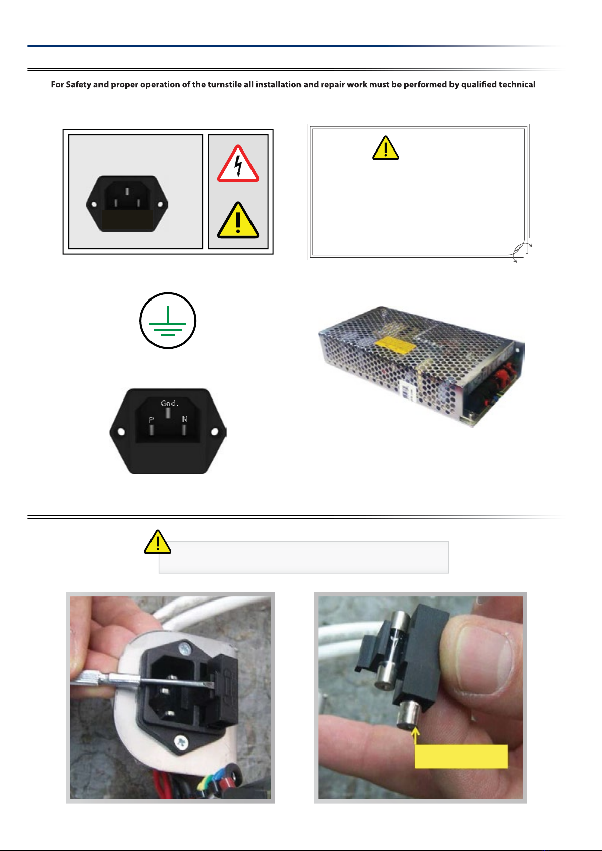
2.3 Safety Related Instructions
1. Users must not dismantle the turnstiles. Maintenance can only be performed by competent and authorized personnel.
Maintenance work attempted by non- qualied individuals may create danger to users and the turnstile.
2. Turnstile must not be installed at places where there is a risk of explosion caused by electrical arcs or a probable gas leakage.
3. Turnstile must be kept away from ammable environments.
4. Turnstile cannot be installed at places where there is vibration.
5. Turnstile must not be kept in excessively moist environments.
6. Turnstile must not be exposed to heat.
7. Turnstile must be kept away from high level magnetic elds.
8. Turnstiles must not be subjected to abusive treatment such as impact or excessive shaking.
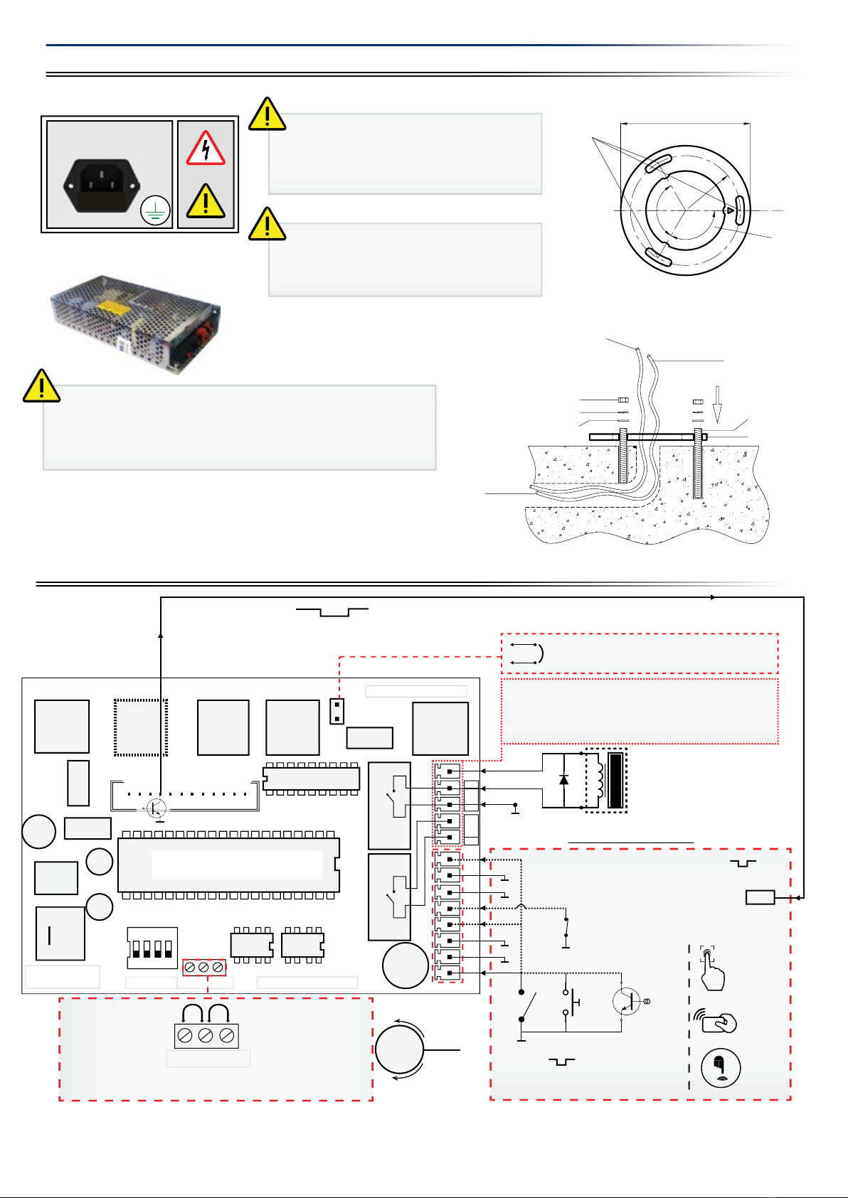
9. Operating voltage/ power range must be observed in all installations. .
10. The power must be stable, properly grounded, insulated.
11. Turnstiles can only be operated under the environmental conditions and temperatures specied by the manufacturer.
12. Children must not be allowed to play with the turnstiles.
13. All connections must be conrmed to be correct before supplying power to the turnstile.
14. No materials or equipment other than what is specied for the turnstile must be used when making connections into the input
and output terminals.
15. All parts and accessories used in the turnstiles must be approved by the manufacturer.
16. In case of any electrical arching or faults caused by such condition, power must be disconnected and authorized servicer or
manufacturer must be contacted as soon as possible.
17. The power must be cut o before cleaning or applying maintenance to the turnstiles.
18. Only clean, soft and moist fabrics (no abrasive materials) should be used for cleaning the turnstile.
19. Damaged turnstiles must not be operated, and the authorized dealer or the Manufacturers technical support center should be
contacted soon as possible for repair.
2.4 Oper
ating Precautions
1. More than one person must not attempt to pass at the same time.
2. Do not obstruct or apply force to the panel at any time.
3. A locked turnstile must not be forced, kicked, abused or tempered with to gain passage without authorization.
4. Turnstiles must not be washed for cleaning purposes (applying water with a hose or pouring water from a bucket. etc).,Wiping o
with non abrasive materials such as a damp cloth is sucient in most cases.
5. Chemicals for cleaning and polishing must not be used in any case. The manufacturer is not responsible for damages resulting
from use of such materials.
3.1 Handling
1. Please pay special attention to carry the turnstiles as originally packed by the manufacturer.
2. Follow the handling and carrying instructions written on the package.
3. Do not place a heavy load on the turnstile package.
4. Do not place the packed turnstile on a wet ground.
5. Do not leave the packed turnstile under rain.
6. During handling, use an appropriate lift/crane with sucient lifting capacity.
7. Before starting installation ensure that there is no shipping damage or missing parts and hardware inside the package.
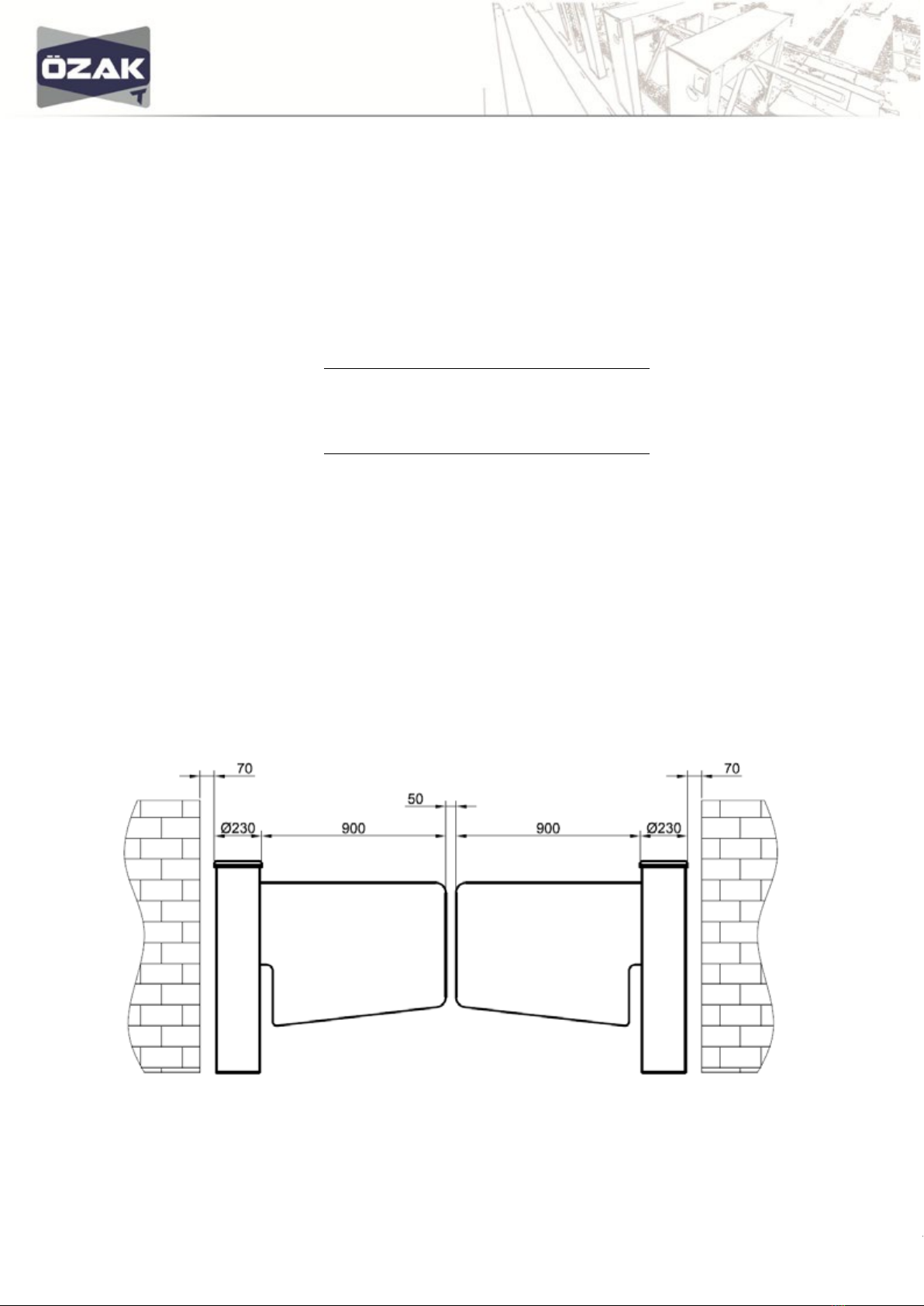
The installation place should be selected according to user's requirements. This selection should not prevent proper
operation of the turnstile.
Ensure that the Installation surface is at, even and of proper strength. Flatten any uneven/rough areas as required.
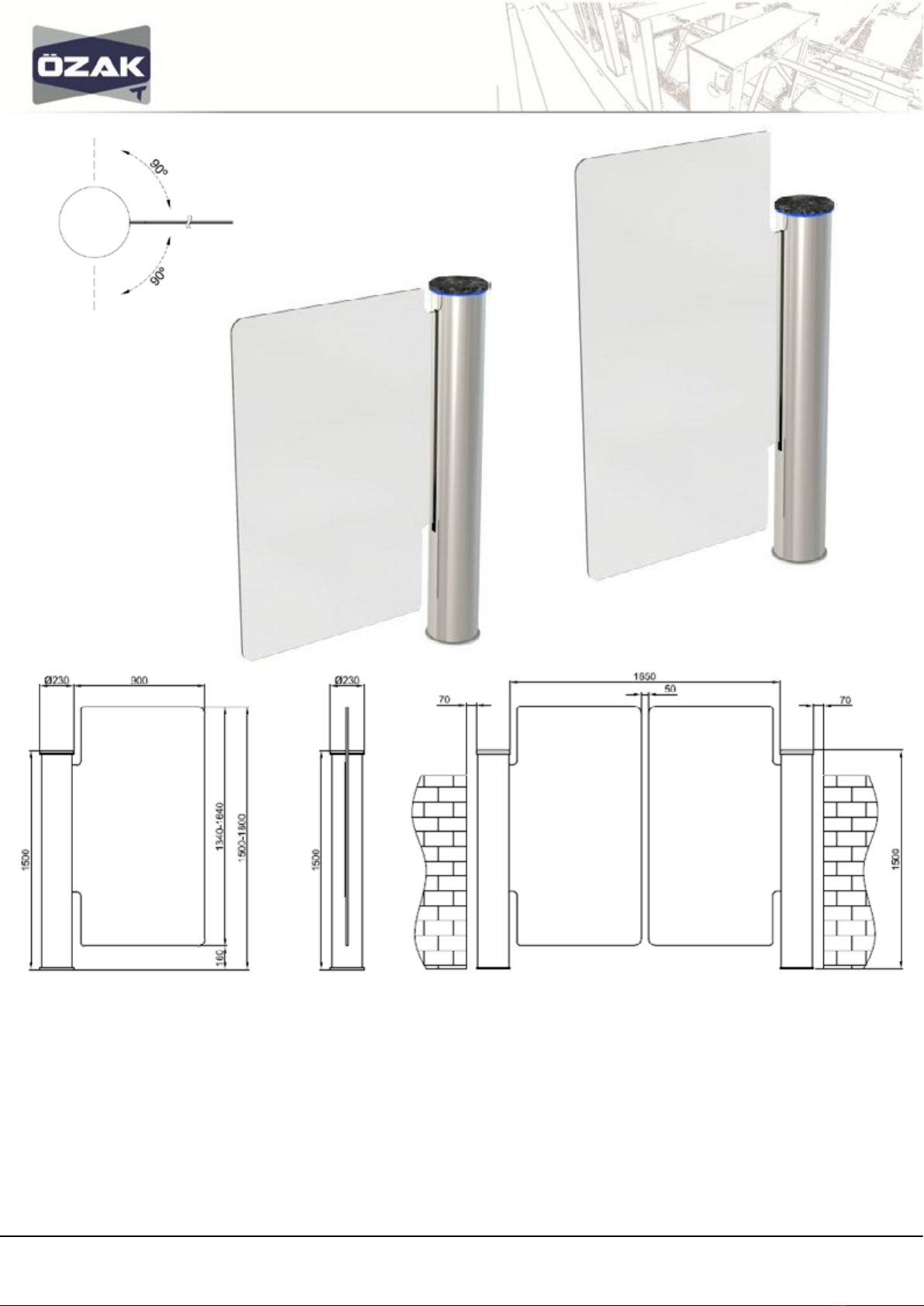
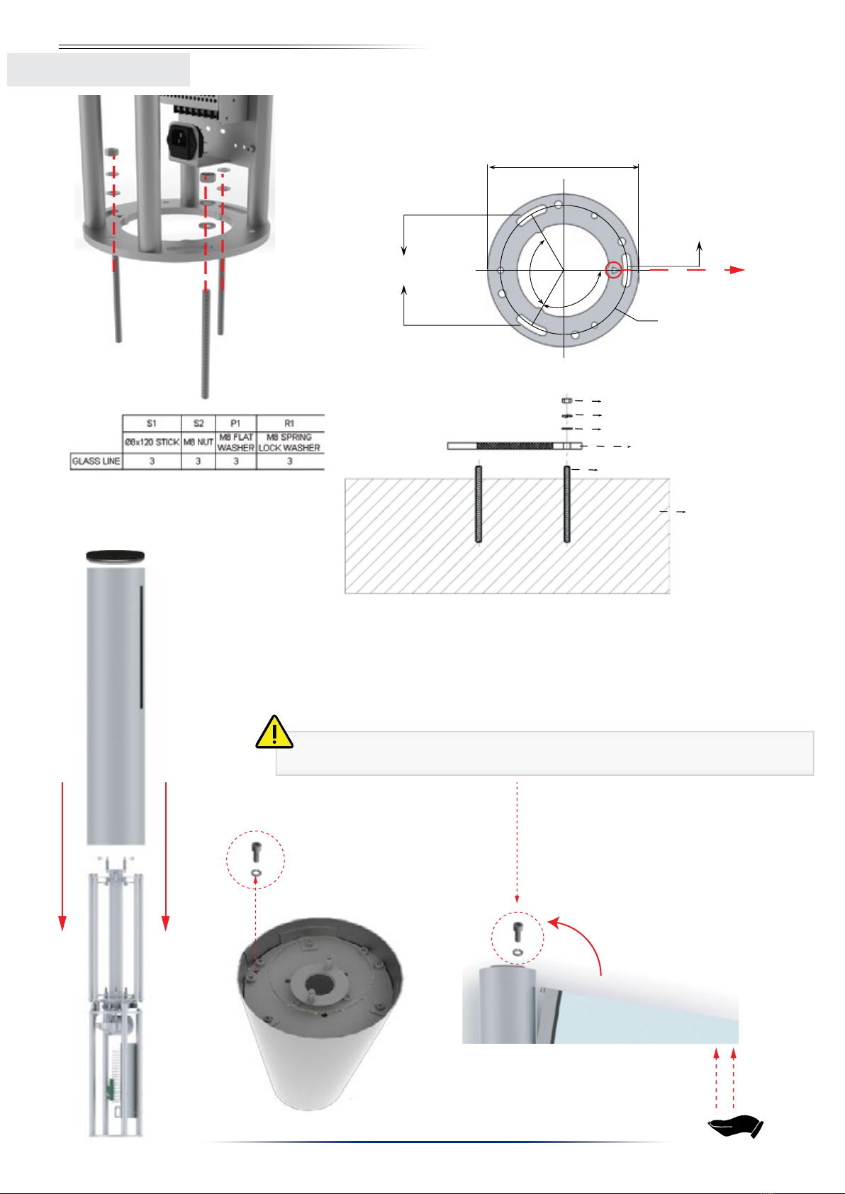
5
3. HANDLING AND INST
ALLATION
3.2 Installation
Removal of Cover Before
Installation:
1. Remove the granite top cover
by pulling upward.
2. Unscrew 3x M6x16 Allien head
screws and washers.
3. Pull up and remove the
stainless steel cylindirical body.
1 2 3
M6 x 16 Hexagon Head Cap
Screw M6 Flat Washer
M6 x 16 Hexagon Head Cap
Screw M6 Flat Washer

DD-75-193 R(0) Y.T.31.03.17
9
S2
R1
P1
S1
S1
S1
S2 R1
P1
6
Caution!
Have panel held securely while tightening or removing panel xing screw (1) to avoid dropping!
Ground
Ø8 x 120 Stick (3 pieces)
M8 Flat washer (3 pieces)
M8 Spring lock washer (3 pieces)
M8 Nut (3 pieces)
Turnstile Base Unit
Ø197 mm
Ø166.5 mm
120º
120º
MOUNTING HOLES
FOR THE FLOOR
MOUNTINGHOLES
FOR THE FLOOR
1. Mark holes and drill with a size 10 drill bit. Clean debris inside the holes by pressurized air.
2. Fill holes with chemical plaster and x anchoring bolts (size 8) in place by rotating.
Chemical plaster dries in about 25 minutes.
3. Place turnstile on anchoring bolts and tighten the nuts to secure in place. Pay attention to
triangle panel position marker during surface mounting
4. Connect power and control cables.
5. Re-install cylindirical body
6. Remove display unit mounting screw (1).
7. Remove glass xing screw (2)
8. Install panel as shown in g. 1 by tilting slightly forward and securely seat on the chasis.
9. Tighten panel xing bolt and nut.
10. Reposition and secure display unit.
11. Install granite top lid in place.
3.2 Installation
Surface Mounting
Panel Mid
Po
sition Marker
1
Wing Mounting
1

DD-75-193 R(0) Y.T.31.03.17
10
4.1 Power and Grounding Connections
4.2 Control Board Connections
4. SETUP AND OPERATION
WARNİNG / DİKKAT
220 V. 50 Hz.
FUSE
ERT
FN
Warning! Power and grounding connections
must be made by a qualied electrician in
accordance with the relevant local regulations
using appropriate materials!
Proper grounding must be ensured to prevent
shock hazard!
Warning! Never remove the protective cover of the power supply
unit for any reason!
In case of a power supply failure, the power supply unit must be
replaced with an original unit obtained from Ozak.
Cable Routing
Area
M8 Washer
M8 Lock Washer
M8 Nut
M8x120 Anchor
Turnstile Base Plate
Ground
1,5 mt (CAT 5, CAT 6 etc.)
Data Cable above surface
1,5 mt 3 x 1,5 TTR
Power Cable above surface
Ø197
120°
120°
Ø166,63
Mounting Holes
Cable Routing
Area
Note: For optimal ow rate contact duration of 1 second or less is recomended.
SN
Access Control Terminal
Res
+24V
B-AB-A or A-B
A-B
N.O.
N.O.
Com
Com
Gnd
Gnd
Emg
INB
Gnd
Gnd
Gnd
Gnd
INA
1
23 7
56
8
- Power +
B-AA-B
J3
Top IndicatorsSide IndicatorsMotor Control
Direction Sensors
ON
DipSwitch
1234
U2
U7
U1
RL1
RL2
U9
A
B
Prg: XXXXXXXXXXX
Rx
Tx
I/O_1
I/O_2
I/O_3
I/O_4
Out_P3
Out_P2
Out_P1
+5 V
+24 V
Gnd
0.5 - 1 sn dry contact
or open collector input
888888
Optional counter
1N4001
or similar
Busy Out
or or
TRN1202
0.5 - 1 sn
busy
B-AA-B
Enable
Gnd
Passage conrmation dry contact output
Use with access control systems, counters etc.
accessories (0.5 sec. N.O. contact)
Buzzer Jumper
(Buzzer disabled when removed.)
Connect a jumper from Enable A-B or B-A to Gnd to block
a passage direction.
Res: Manual Time Reset (Optional)
24 VDC
Optional counter
sample connection
During Passege = 0
Emg: Emergency-Free Access Mode
(when contact is open.)
Gnd
Enable
TURNSTİLE POWER WARNING LABEL
Ground (GND)

DD-75-193 R(0) Y.T.31.03.17
11
8
4.3 Control Board Settings
4.3.2 Timeout and Mode Settings by Dip Switch
To block entry into A or B direction, short enable terminals. Turnstile will not alow passage in the blocked direction. This feature can be
used with a metal detector to automatically block access for security purposes or setting the turnstile for one way trac operation.
4.3.1 Blocking Passage Directions (Inhibit)
TIME SELECTION
WSWS
NOITANALPXE21
FFOFFO Entry Time Out 6 Seconds
FFONO Entry Time Out 12 Seconds
NOFFO Entry Time Out 2 Seconds
NONO Entry Time Out - Infinite
PANEL OPENING DIRECTION IN EMERGENCY
WS
NOITANALPXE3
FFO OPEN CLOCKWISE IN EMERGENCY
NO
OPEN COUNTERCLOCKWISE IN
EMERGENCY
BUTTON MODE SELECTOR
WS
NOITANALPXE
FFO
SEPARATE OPEN AND CLOSE
BUTTONS
NO
OPEN AND CLOSE WITH A SINGLE
FIG. 2
FIG. 3
FIG. 4
FIG. 1
BUTTON INTO IN A OR B
FIG. 1 FIG. 2 FIG. 3
babab
ab
a
Emg
FIG. 4
Emg
Connect a jumper from Enable A-B or B-A to Gnd to block a passage direction.
ab ab
BLOCKED
CONTAC TCONTAC T
BLOCKED
ON
OFF
ON
OFF
ON
OFF

DD-75-193 R(0) Y.T.31.03.17
12
9
1. Turnstile is factory preset (see dip switch settings) for bi-directional controlled access. For one way access, or single button/ reader
operation please refer to 4.4 Control Board Settings
2. After completing the installation steps, gently bring the panel to the center position and apply power . Buzzer is heard, RGB indicator on
top ashes white for a few seconds and then buzzer stops, RGB indicator turns blue indicating that the turnstile is in standby mode.
3. When a momentary contact is given into ’INA’ terminal, top indicator ashes green, buzzer is heard and panel opens by turning 90
degrees in clockwise direction. Panel remains open for 6 seconds (default setting) and then returns to center. For opening in the
opposite direction a contact is required on ‘INB’ terminal.
4. Panel remains open when continuous contact is present on INA or INB.
5. If a continuous contact is given on Emg. terminal, buzzer is heard, indicator ashes green, panel opens in clockwise and remains open for
duration of the contact. This feature can be used with re alarm system to open the gate automatically when the alarm is activated. To
open in counterckockwise direction, set dip switch 3 ON.
6. When the panel is held or meets an obstacle during movement after opening more than 30 degrees, it moves back and tries to advance
once more. If the obstacle is still present panel stops and alarm is heard. Alarm resets after 10 seconds.
7. If the panel is forced excessively, a built in electronic circuit breaker will be activated and power to motor is disconnected. In this case a
power o reset is required to restore normal operation.
5. POST INSTALLATION CHECK LIST
No Item to Check
√
Remarks
1 Installation surface is flat, even and sufficiently strong
2 All wiring is routed and connected properly
3 All AC power lines are properly insulated and grounded
4 Turnstile is positioned and mounted correctly and firmly
5 All anchoring bolts are secured in place with chemical plaster.
6 All anchoring hardware tightened properly (no loose nuts/bolts
etc).
7 Panel, covers, readers etc. are mounted correctly. Panel is
securely bolted in place
8 No physical damage or irregularities (dents, scratches, broken
items ets.)
9 When powered up buzzer is heard, indicator is blue, rotor/panel
in standby position)
10 Turnstile allows passage in A direction (opens clockwise) when
contact is given on Input A and Gnd and indicator turns green.
11 Turnstile allows passage in B direction (opens counterclockwise)
when contact is given on Input B and Gnd and indicator turns
green.
12 Turnstile operates quietly, smoothly and returns to center
(standby) position after the pre-set time elapsed (6 sec default)
13 When Emg contact is given continuously turnstile opens for free
passage..
14 When power is cut off, turnstile allows free passage by pushing
15 AC potential between turnstile ground and neutral is less
than 0.5V. Good continuity (0 Ohm) between chassis and
ground.
Unit is properly grounded.
4.4 Operating Instructions
SN
Access Control Terminal
Res
+24V
B-AB-A or A-B
A-B
N.O.
N.O.
Com
Com
Gnd
Gnd
Emg
INB
Gnd
Gnd
Gnd
Gnd
INA
1
23 7
56
8
- Power +
B-AA-B
J3
Top IndicatorsSide IndicatorsMotor Control
Solenoid Out Direction Sensors
ON
DipSwitch
1234
U2
U7
U1
RL1
RL2
U9
Prg: XXXXXXXXXXX
Rx
Tx
I/O_1
I/O_2
I/O_3
I/O_4
Out_P3
Out_P2
Out_P1
+5 V
+24 V
Gnd
0.5 - 1 sn dry contact
or open collector input
888888
Optional counter
1N4001
or similar
or or
TRN1202
0.5 - 1 sn
B-AA-B
Enable
Gnd
Passage conrmation dry contact output
Use with access control systems, counters etc.
accessories (0.5 sec. N.O. contact)
Res: Manual Time Reset (Optional)
24 VDC
Optional counter
sample connection
Emg: Emergency-Free Access Mode
(when contact is open.)
Gnd
Enable

DD-75-193 R(0) Y.T.31.03.17
13
6.1.1 Rec
omended User Maintenance
10
6.1.2
Periodic Maintenance by Technical Service Personnel
6. SERVICE AND MAINTENANCE
6.1 Maintenanc
e Instructions
• Periodically wipe the turnstile exterior with a clean, damp and soft cloth to keep it free of dust.
• Inspect panel, cover, body etc. once every three months or as required to ensure that there are no loose, worn out or damaged
items.
• Check that the turnstile is firmly anchored on the surface.( No loose or damaged anchoring).
• Check that all mechanical movement is smooth and quiet with no unusual noise, rattling etc.
•Inspect electrical cables and connections for any damage, water contamination, loose connections or wear. Contact your autho-
rized dealer or the manufacturer if any problem is detected.
• Ozak uses only the finest quality certificated steel obtained from reputable suppliers for maximum corrosion resistance and
strength. During the manufacturing process all the required procedures are completed to ensure that the finished products have
excellent corrosion resistance.
• Depending on the environmental conditions, there may be tea staining issues on some turnstile surfaces in moist/ dusty areas if
regular cleaning and maintenance is not performed. On 304 and higher grade steel surfaces, these stains are not actual rust, but
only accumulation of airborne particles sticking on the surfaces. These type of stains can be cleaned off and prevented by periodic
maintenance recommended below.
Do not wash the turnstile with water. GLA1 is designed for indoor applications only. There are no user serviceable items inside the
turnstile. Do not attempt to do repair work such as lubrication, part replacement, adjustment inside the unit. All such work must be
performed by qualied technical personnel only!
GLA1 Maintenance Item Period Action
General Covers and anchoring bolts 12 mt. Check/ tighten
Reader and other munted accessories 12 mt Check
Panel (tight and secure-no play) 12 mt Check
Mechanism Rotor shaft 12 mt Check
Motor 12 mt Check
Gears 12 mt Check + Lubricate
Bearings 12 mt Check
Electrical Control Board 12 mt Check + Remove dust
Directional Photosensor 12 mt Check + Remove dust
Wiring and connectors 12 mt Check
Indicators and buzzer 12 mt Check
Maintenance Notes:
.................................................................................................................................................................
.................................................................................................................................................................
.................................................................................................................................................................
.................................................................................................................................................................
.................................................................................................................................................................
.................................................................................................................................................................
.................................................................................................................................................................
.................................................................................................................................................................
.................................................................................................................................................................
.................................................................................................................................................................
.................................................................................................................................................................
.................................................................................................................................................................
.................................................................................................................................................................
.................................................................................................................................................................
.................................................................................................................................................................

DD-75-193 R(0) Y.T.31.03.17
14
11
6.2 Trouble Shooting and Repair Guide ( Refer all repair work to qualied technical service personnel! )
6.3 Motor Driver Adjustments
CURRENT ADJUSTMENT PROCEDURE:
The motor driver board has an overcurrent protection feature with adjustable threshold by RV1.
1. Do not change speed setting unless a replacement board is installed. Otherwise, set the speed at factory default .
2. Adjust‘current’ carefully by observing red ‘overcurrent’ LED. The LED should blink for minimal duration each time the motor
starts. If the led blinks too long and brightly, turn adjustment left (CCW) for minimal ash duration.
Note: If the speed setting is changed,‘current’ must be re-adjusted.
Caution!
Panel may stall and retreat with no obstacle if RV1 setting is too low. In this case turn RV1 counter clockwise to reduce sensitivity.
If the setting is too high then panel may exert excessive pressure on an obstacle.
Description of Fault Possible Cause Recommended Action
No power. (indicators, buzzer
o)
1. No AC power supplied to unit.
2. Loose power cable
3. Blown fuse
4. Faulty power supply unit
1.Restore AC power.
2. Connect power cable.
3. Replace fuse (see 2.2)
4. Replace power supply unit
Turnsile does not allow
passage when input contact
is given-buzzer heard,
indicator turns green
1. Restricted panel movement (due to
foreign object blocking movement)
2. Motor driver circuit breaker tripped
3. Loose motor connection
4. Blown motor driver fuse
5. .
1.Remove object
2. Power o reset
3. Repair connection
4. Replace motor driver board fuse
Panel oscillates right and left
in the middle position 1. Misaligned/ bent photosensor Adjust photosensor (reduce angle)
No response to input/reader
Turnstile remains open with
alarm sound.
device. No access
1. Loose/incorrect reader connection
2-Reader fault
1. Emergency (Emg) input jumper removed.
2.Fire alarm relay connection fault.
1. Connect jumper on Emg-Gnd terminals
2.Repair re alarm (NC)connection
3-Faulty control board
1.Check/repair reader connections
3-Replace faulty reader/input device
4-Replace control board
Motorized rotor/ panel keeps
moving/ fails to stop in
middle position.
1. Loose photosensor connector
2. Misaligned, bent or contaminated
photosensor
3. Faulty photosensor
1. Repair/tighten photosensor connector
2. Adjust/ clean photosensor
3. Replace photosensor
Motorized panel opens
slowly and times out on
return/ alarm activated.
1. Too low motor speed settingon motor
driver board
1. Increase motor speed (turm speed control ccw
direction) on motor driver board
Speed Adj.
Overcurrent LED
Current Adj.
5.
Electronic circuit protection activated
Power o reset

DD-75-193 R(0) Y.T.31.03.17
15
6.4 Photo Sensor Replacement and Alignment
1. Power o unit and Remove Sensor Plug #6
3. Remove 2 sensor screws with 3 mm.
Allen key) and take out plastic spacers
4. Remove Photosensor Unit 5. Check new photosensor for proper centering 6. Check photosensors for proper alignment
8. Check/align sensors for proper clearance
with disc and all moving parts.
2. Move mechanism to center position
7. Install photosensor unit (follow removal steps in
reverse order) – Insert into plug #6
CAUTION! Do not insert into any other
plug-This will damage photosensor unit.
12

DD-75-193 R(0) Y.T.31.03.17
16
6.5 Motor Replacement
13
4. Remove motor mount screw‘1’ by 5 mm allenkey 5. Remove motor mounting screw‘2’ by 5 mm
allenkey
6. Remove remaining motor mounting bolt by10
mm wrench and remove motor. Follow stepsin
reverse to install new motor.
1. Turn rotor to gain access to sensor xing screw.
Remove screw by 3mm. allen key while holding
bottom nut with 7 mm wrench
2. Carefully push photosensor unit back for access
to motor mounting bolts
3. Loosen lock screw by 4 mm allen key

DD-75-193 R(0) Y.T.31.03.17
17
6.5 Motor Replacement
13
4. Remove motor mount screw‘1’ by 5 mm allenkey 5. Remove motor mounting screw‘2’ by 5 mm
allenkey
6. Remove remaining motor mounting bolt by10
mm wrench and remove motor. Follow stepsin
reverse to install new motor.
1. Turn rotor to gain access to sensor xing screw.
Remove screw by 3mm. allen key while holding
bottom nut with 7 mm wrench
2. Carefully push photosensor unit back for access
to motor mounting bolts
3. Loosen lock screw by 4 mm allen key
6.6 Schematic Diagram
14
+-
Control Board
Motor Driver Board
Brake Relay Board
PHOTO SENSOR
24VDC Power Supply
220 V AC
Gnd
NP
RGB
LED INDICATOR M
12 V DC IN
d
PHOTO SENSOR
NN
-
2
4
V
D
C
Power Supp
l
y
+
BLUE
YELLOW
BLACK
BLACK
BLACK
RED
RED Fuse
RED
BLUE
YELLOW
BLACK
GREEN
YELLOW
GREEN
RED
Main Power
Data Conn.
1-Direction
2-Start/Stop
3-OverCurr
4-Mt.Break
D4
Q2
U3
U2
MCT6
1213H
MCT6
1213H
U1
F1
R3
U4
RV2
RV1
RL2 RL3RL1
9
7+24v
1234
Fuse Ind.
Motor Out
Motor Ind.
Current Adj.
J4
Speed Adj.
Over Curr. Ind.
Brake Ind.
S/
N:
C
/N
:
P
/N
:
+12v
out
Batt Gnd
+
+
-
-
SN
Res
+24V
B-A
A-B
N.O.
N.O.
Com
Com
Gnd
Gnd
Emg
INB
Gnd
Gnd
INA
1
23 7
56
8
- Power +
B-AA-B
J3
Direction Sensors
ON
DipSwitch
1234
U2
U7
U1
RL1
RL2
U9
Prg: XXXXXXXXXXX
Rx
Tx
I/O_1
I/O_2
I/O_3
I/O_4
Out_P3
Out_P2
Out_P1
+5 V
+24 V
Gnd
TRN1202
Gnd
Enable
1 2 3 4 5 6
1 2 3 4 5 6
1 2 3 4 5 6
1 2
1 2 3 4 5 6
BLACK
Dr
R
o
nn.
2
V
2
4
Gnd
r
D
a
Co
Q2
U
3
RV
7
7
3
ON
D
i
p
1
+
24
V
Gnd
or
D
at
a
7
7
2
p
Swi
2
3
O
O
O
Out
_P1
O
O
+5
V
M
ot
o
D
t
i
o
n
1
-D
i
rec
t
/
Stop
2
-Start
/
Cu
rr
3
-
OverC
Curr
3OverC
r
ea
k
4
-Mt.B
r
D
4
1
M
otor In
d
.
Speed
Adj.
Speed
Adj.
+
-
R
es
+
24
V
B-
A
A
-
B
N.O
.
N.
O.
C
om
C
om
Gn
d
Gn
d
E
m
g
IN
B
Gn
d
Gn
d
INA
B
-A A-
B
tch
3
4
U2
U7
U
1
R
L1
R
L2
U9
P
rg: XXXXXXXXXX
X
Rx
Tx
I/O_1
I/O
_
2
I
/O
_
3
I
/O
_4
O
ut
_
P3
Out
_P2
O
Out
P1
O
TRN1202
G
n
d
Enable
Enable
YELLOW
RED
BLACK
GREEN
in

DD-75-193 R(0) Y.T.31.03.17
18
15
CONNECTOR PIN CONFIGURATION TABLES
CAUTION! Pin and connector numbers
MOTOR DRIVER BOARD
1
2
3
4Gnd.
POWER
+24Vdc
Batt.In
+12Vdc (For Led Strip)
1 2 3 4 1Direction Control
2
3Overcurrent Detect
4Motor Brake Control
CONTROL CONN.
Start/Stop Control
7
1Motor Out(Brown)
2Motor Out(Blue)
9
MOTOR OUT
12
Match socket and cable numbers when
replacing boards and other parts !
Pay attention to pin markers when
replacing microprocessors !
CONTROL BOARD
1
2
3
4
Sensor 2 Data In
Gnd
+24Vdc
Sensor 1 Data In
6
PHOTO SENSOR INPUT
1Gnd
2+24Vdc
POWER 8
1
2
3
4
5
6
n.c
n.c
3
n.c
RGB LED STRIPE
n.c
Blue Led Stripe
Red Led Stripe
1Relay Out 1Red
1
(5 not used)
1
2
3
4
5
6
n.c
n.c
n.c
B-A Green Led Stripe
n.c
2
RGB LED STRIPE
A-B Green Led Stripe

DD-75-193 R(0) Y.T.31.03.17
19
7. LIST OF REPLACEMENT PARTS
REF Part Description Part Number
1
2
Directional Photosensor
30 01 14 0001
3
Electronic Control Board (1202) 30 01 06 0003
4
Glass Wing *
5
Motor (24V/60W) 30 01 16 0002
6
Motor Driver Board (MC24) 30 01 03 0011
7
Power supply (SMPS) 100W/ 24V 10 01 35 0013
8
RGB Indicator Led 45 00 00 0004
9
Rubber Stop 20 02 03 0023
Top Lid (Marble) 30 03 00 1144
10 Cylinder 30 03 00 0020
Use only original Özak replacement parts!
2
4
1
6
5
3*
7
9
10
* Panel type and size can vary depanding on option choosen.
*Please provide model and serial number of the turnstile when ordering parts.
**Part numbers can vary depanding on pruduction date.

DD-75-193 R(0) Y.T.31.03.17
20
Warranty Certificat
e
BRAND NAME :
..............................................................................................
MODEL :
..............................................................................................
DATE OF DELIVERY :
..............................................................................................
W
ARRANTY PERIOD
:
..............................................................................................
SERIAL NUMBER
:
...............................................................................................
MANUFACTURER : ÖZAK GEÇİŞ TEKNOLOJİLERİ SANAYİ TİC A.Ş.
ADDRESS : Çuhane CD. N0: 130 41080 KÖSEKÖY / KOCAELİ / TURKEY
PHONE&FAX : +90 262 373 48 48 Pbx.
WEB : www.ozak-t.com
TSEK TS EN ISO 9001:2008
T-233/01
This manual suits for next models
3
Table of contents
Other OZAK Turnstile manuals