Tansa LTT 303 User manual

TRIPOD TURNSTILE
USER MANUAL

| 2 |

CONTENTS
Introduction
5
Chapter 1: General Information
1.1 General specifications……………………..………………………………..…….……..
6
1.2 Tripod turnstile types.………………………………………..…………………...…..….
7
1.3 Package Contents…………………………………………………………….………..…
8
1.4 Hardware changes……………………………………………………………………….
8
1.5 Symbols and definitions…………………………………………………………...…...
8
Chapter 2: Technical information
2.1 TechnicalSpecifications……….……………………………………………..…..……
9
2.2 Technical specifications table…………………………………………………….….
10
2.3 Optional accessories…………………………………………………....……………..
11
Chapter 3: Installation and Assembly
3.1 Required tools…………………….…………………………………………………..
12
3.2 Field preparation………....………………………………………………...….…….
13
3.2.1 Floor Mounting ………………………………………………………………
14
3.2.2 Cabling…………………….…………………………….……………...……..
15
3.3 Turnstile hub assembly…….…………….………………..….…………….…..….
16
3.4 Turnstile arm assembly……………………………………………….................…
17
3.4.1 Drop arm assembly…………………………………….….…………...…….
17
3.4.2 Normal arm assembly…………………………………….…..………………
17
Chapter 4: Turnstile mechanism information
4.1 Internal parts……………………………………………..………………………....…
18
4.2 How to open the cover………………………………………………………………..
19
4.3 Turnstile mechanism…………………………………..….……………………….…
20
4.3.1 Shock absorber adjustement…………………………..………………………
21
| 3 |

4.4 Guiding indicators………………………………………………………………...
22
4.5 Supply unit and grounding…………………………………….…………...……..
23
Chapter 5: Electrical Connections
5.1 Control card and specifications…………………………………………………….…
24
5.2 TEC-101 control card……………………………………………………………….…
27
5.3 Control card key descriptions……………………………………………….…….….
28
5.4 Control card terminal descriptions (XL5)
30
5.4.1 External connection types………………………………………………….....
31
5.4.1.1 Triggering with dry contact……………………………………………..
31
5.4.1.2 Triggering with energy input……………………………………………
31
5.4.2 Alarm cable group turnstile connection…………………………………….
32
5.5 Control card terminal descriptions (XL9) ………………………………………….
33
5.5.1 How to use pass relays…………………………………………………….....
34
5.5.2 Pass relays and counter connection
34
Chapter 6: Product Usage Instructions
6.1 Safety and Operating Instructions…………………………………………………..
35
6.2 Maintenance Instructions…………………………………………………………....
36
Chapter 7: Fault Condition
7.1 Troubleshooting………………………….……………………………………....
37
Chapter 8: Warranties
8.1 Warranty conditions…………………………………………………………......
40
8.2 Out of warranty conditions……………………………………………………..
41
8.3 Warranty certificate……………………………………………….……………..
42
Chapter 9: Quality certificates
9.1 Management system certificate and attachment………………………..…….
9.2 CE certificate and TSE certificate………………………………….……..........
43
44
| 4 |

INTRODUCTION
Dear valued customer,
Thank you for choosing our tripod turnstile. We want to offer you the best efficiency.
Please read this manual carefully. This manual contains detailed information on the installation
and maintenance of turnstiles. The information contained in this manual is of great importance
in order to extend the service life of the turnstile and to obtain maximum efficiency.
Turnstiles have an active place in our daily lives and are used in many areas. It is possible to
see them in several places such as public transportation stations, business and training centers,
parks, dining halls, stadiums, prisons, etc.
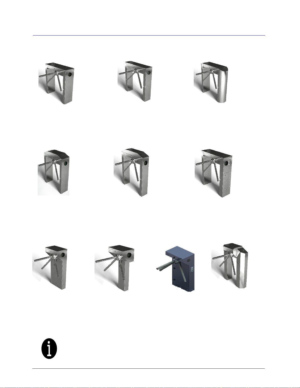
The nature and purpose of the areas where turnstiles are used is the biggest factor in the
design and production of turnstile models. Our products, which are created by taking this factor
into consideration, are grouped into four main categories: Tripod turnstiles (waist high turnstiles),
Swing gate turnstiles (handicapped accessible turnstiles), Full-height turnstiles, and Speed gate
turnstiles. In addition, Full-height turnstiles and the Speed gate turnstiles also have handicapped
accessible versions.
Turnstiles can be produced as stainless steel, galvanized or electrostatic powder-coated
according to customer demands. Optionally, different solutions are available for some product
models.
Turnstiles are compatible with any kind of magnetic, biometric, proximity and similar
readers. In addition, applications such as buttons, coins, remote controls can be integrated and
used with a turnstile.
All materials used in the turnstiles are designed to be water and dust resistant and tested in
accordance with IP44 standards. Mechanical parts of the turnstiles are protected against corrosion
and oxidation with AISI 304 stainless steel and zinc plating.
Turnstiles can work in both directions. The anticipated use per hour is at the level of 1500
persons.
All TANSA brand turnstiles have certificates of compliance with TSE, ISO 9001 and CE
standards.
HEADQUARTER:
Address: Eyüp Sultan Mahallesi. Hoca Nasreddin Caddesi. No: 10
Sancaktepe / İSTANBUL
Phone: +90 (216) 561 96 71-72-73
Fax: +90 (216) 561 96 74-75
E-mail: [email protected]
| 5 |

1.1 General specifications
Working Direction: Turnstiles can work in both directions regardless of model and category.
They can be used as entry and exit.
Movement and Drive: Arms of the tripod turnstile move manually. There is no need to touch
the arms of the turnstile with hands. The arm rotates easily with body contact.
Case / Frame Material: Tripod turnstile can be made of 1.2mm in standard, or 1.5 mm or
2mm based on order, AISI 304 quality stainless steel or of 1.5 mm DKP sheet as electrostatic
powder-coated.
Rotor, Arm and Wing Parts: In the waist high turnstiles, arms are threaded joint mounted
and made of polishing covered hard aluminum. In drop arm turnstiles, arms are designed as screw-
mounted. Arms can also be manufactured as stainless steel.
Turnstile Functions: Electronic microprocessor control allows passage in both directions,
and provides usage information. Users are guided by the indicators on the turnstile. The contact,
opening and automatic closing times of the turnstile can be set on the electronic control panel. The
memory mode allows faster passage. The turnstile can be operated on locked to the desired
direction mode or free mode while in standby. Optionally, a passage indicator can be added on the
cover.
| 6 |
GENERAL
INFORMATION
1

GENERAL INFORMATION
1.2 Tripod turnstile types
LTT 303/ LTT 303A/ LTT 313/ LTT 313E/ LTT 323 turnstiles models have double versions.
| 7 |
LTT 303:
Normal case
double leg tripod
turnstile
LTT 303S:
Narrow case
double leg tripod
turnstile
LTT 303E:
Special cover
cylindrical
double leg tripod
turnstile
LTT 303A:
Angle Cover
Double Leg
Tripod Turnstile
LTT 303AS:
Narrow case,
angle cover
double leg tripod
turnstile
LTT 303J:
Coin operated
double leg tripod
turnstile
LTT 313:
Single-narrow leg
tripod turnstile
LTT 313EJ:
Coin operated
single-wide leg
tripod turnstile
LTT 313E:
Single-wide leg
tripod turnstile
LTT 323:
Wide case
tripod turnstile

GENERAL INFORMATION
1.3 Package Contents
Package contents may vary according to the turnstile models. Make sure that the package
contents below are complete. If you find any deficiency or fault, please contact TANSA.
A standard turnstile package should include:
•
1 pcs LTT 3XX Turnstile
•
3 turnstile arms (6 turnstile arms on double turnstile models)
•
1 pcs cover opening key
•
1 pcs shock absorber hex key
•
Stud and nut for fixing
•
User manual
1.4 Hardware changes
As the IP44 protection of the turnstile becomes invalid in any change made on the turnstile,
any mechanical or electronical change shall not be made without the permission of TANSA, and
TANSA shall not be liable for any problems that may arise otherwise. The intended change must
be notified in writing to TANSA in advance. Additional technical information, warnings and
precautions may be provided by TANSA if necessary.
1.5 Symbols and definitions
The symbols and descriptions in the user manual are shown below.
Important information and useful tips on using the turnstile.
Warning against dangerous situations in terms of life and property.
| 8 |

2.1 Technical specifications
Mechanism Specifications: The mechanism is made of hardened aluminum casting, the cams
and locking tabs on the mechanism are made of AISI 304 stainless steel.
Power Source: All the turnstiles can work with 110/220 VAC. The operating frequencies of the
turnstiles are 50 / 60 Hz.
Internal Voltage: There is no high voltage in any components except the supply unit in the
turnstile. Depending on the turnstile model, 24/12 VDC internal voltage is measured.
Power Failure and Emergency Mode: All tripod turnstile models have emergency mode and
are compatible with all types of fire / alarm panels. As soon as the emergency switch is on, the
turnstile guiding indicators blink in the shape of green arrow and give sound warning, the arms are
released in the unlocked position (LTT-3xx-DA) allowing free access. In the case of power failure
in tripod turnstiles, arms run idle or drops in the drop-arm models allowing free access. In drop-
arm models, arm should be lifted to the locked position by hand when the power is back.
Operating Temperature: Turnstiles can work smoothly in the temperature range between -10
and +70 degrees. It is recommended to use a thermostat heater, optionally, at temperatures lower
than -10 degrees.
Transport and Storage Temperature: -20 to +80 degrees.
Relative Humidity Ratio: Maximum 95%.
| 9 |
TECHNICAL
INFORMATION
2

TECHNICAL INFORMATION
2.2 Technical specifications table
Model
Height
Length
Width
Weight
Power
consumpti
on
Operating
temperature
LTT - 303
980 mm
840 mm
280 mm
~35 kg
Max. 4.1 W
-10° to +70°
LTT - 303D
980 mm
840 mm
500 mm
~55 kg
Max. 8.2 W
-10° to +70°
LTT - 303A
1045 mm
840 mm
280 mm
~35 kg
Max. 4.1 W
-10° to +70°
LTT - 303AD
1045 mm
840 mm
500 mm
~55 kg
Max. 8.2 W
-10° to +70°
LTT - 303S
980 mm
840 mm
200 mm
~30 kg
Max. 4.1 W
-10° to +70°
LTT - 303AS
1045 mm
840 mm
200 mm
~30 kg
Max. 4.1 W
-10° to +70°
LTT - 303E
1000 mm
1000 mm
280 mm
~45 kg
Max. 4.1 W
-10° to +70°
LTT - 303J
980 mm
880 mm
280 mm
~40 kg
Max. 5.1 W
-10° to +70°
LTT - 313
1020 mm
450 mm
300 mm
~25 kg
Max. 4.1 W
-10° to +70°
LTT - 313D
1020 mm
450 mm
500 mm
~40 kg
Max. 8.2 W
-10° to +70°
LTT - 313E
1020 mm
450 mm
300 mm
~30 kg
Max. 4.1 W
-10° to +70°
LTT - 313ED
1020 mm
450 mm
500 mm
~45 kg
Max. 8.2 W
-10° to +70°
LTT - 313EJ
1020 mm
450 mm
300 mm
~25 kg
Max. 5.1 W
-10° to +70°
LTT - 323
1030 mm
800 mm
300 mm
~30 kg
Max. 4.1 W
-10° to +70°
LTT - 323D
1030 mm
800 mm
525 mm
~55 kg
Max. 8.2 W
-10° to +70°
The power consumption in the table indicates the power used by the turnstile at idle. The
power consumption is reduced by 10% during operation.
|10 |

TECHNICAL INFORMATION
2.3 Optional accessories
Model
LED *
Button
Box
Card
reader
device
Coin
Unit
Drop
arm
Counter
Heater
Illegal
pass
alarm
Top
cover
pass
LED
LTT - 303
LTT - 303D
LTT - 303A
LTT - 303AD
LTT - 303S
LTT - 303AS
LTT - 303E
LTT - 303J
LTT - 313
LTT - 313D
LTT - 313E
LTT - 313ED
LTT - 313EJ
LTT - 323
LTT - 323D
*Guiding indicator
Descriptions of the signs in the table:
: Standard in the turnstile model.
: Can be added optionally to the turnstile model.
: Not applicable for the turnstile model.
| 11 |

3.1 Required tools
The tools required for the installation of the turnstile are listed below.
| 12 |
INSTALLATION AND
ASSEMBLY
3
10/12 mm
drill bit
Meter
Chemical adhesive
Hammer drill
Crimper
Torque
wrench
Socket wrench
17/13 mm
socket
Spirit level
Phillips head
screwdriver
Flathead
screwdriver
5mm hex

INSTALLATION AND ASSEMBLY
3.2 Field preparation
Turnstile dimensions differ according to the selected turnstile. It can be placed in the
specified area in desired way and position. Figure 3.1 shows a section of LTT 303's layout.
Figure 3.1 Turnstile layout
There are some instructions to place the turnstiles.
Instructions:
•The floor where the turnstiles are to be mounted must be completely flat and balanced.
Installation should not be done if there is any bumps and slopes on the floor.
•Under the floor, which the turnstile is to be mounted, must not be empty. No mounting
should be done on non-durable floors such as plasterboard, gypsum, sand etc.
•There should be no installation or cable under the floor where the turnstile is to be mounted.
If necessary, it should be specified as a plan or project and mounted according to this
information.
•No dust should be left in the holes while mounting of the turnstile on the floor. If possible,
please remove the dust with a pneumatic hose or similar tools.
•Chemical mixture epoxy should be used while mounting the turnstile on ground and no
work should be done before the freezing time (30 min) is completed.
•Mounting rods of 10 mm thickness and 150 mm length must be used to mount turnstiles on
the floor.
•Before starting the installation of the turnstile, make sure that the conditions described in
the "installation and assembly" chapter are present.
| 13 |

INSTALLATION AND ASSEMBLY
3.2.1 Floor mounting
After placement and positioning, the floor mounting of the turnstiles should be carried out
according to the information given. Mounting brackets of the turnstile may vary by model and
category. Mark the leg parts of the turnstiles by drawing around the area where it touches the
floor. (Figure 3.2) Remove the mounting brackets screwed on the turnstile feet or body by using
an M6 hex key. (Figure 3.3)
Figure 3.2 Figure 3.3
Place the mounting bracket on the floor 2mm inside by leaving equal space on the right and
the left, then mark the mounting points on the floor (Figure 3.4). After marking all the brackets in
this way, connected them firmly to the floor by screwing in the holes (Figure 3.5).
While screwing, pay attention to the position of the bracket that must have equal space on
the right and left.
Figure 3.4 Figure 3.5
| 14 |

INSTALLATION AND ASSEMBLY
Place the power cable and control cables through the turnstile in a way to leave the brackets inside
the turnstile. Tighten the previously unscrewed M6 hex keys. You have now completed the
mechanical installation of turnstiles. (Figure 3.6 and Figure 3.7) The next step is connecting the
power cable and control cables.
Figure 3.6 Figure 3.7
3.2.2 Cabling
Use a 3x1.5mm TTR power cable and 6A fuse for the turnstile supply. Grounding must be at
least 25 amperes. A separate cable line must be installed for data and fire contact cables to card
readers or other turnstile control devices to be connected to the turnstile. Data and fire cables must
be installed in the same with electric cables.
In places where a large number of turnstiles are installed side by side, emergency cables
must be installed from one turnstile to the other. This parallel connection must be made in
accordance with the emergency connection diagram.
|15 |

INSTALLATION AND ASSEMBLY
3.3 Turnstile hub assembly
There should be no power in the turnstile during the assembly process.
Figure 3.8 Hub assembly
The image shows the LTT 303 model turnstile, but all of our tripod turnstile hubs are
assembled in the same way. Turnstiles are delivered from our factory as assembled. The turnstile
hub consists of 6 parts in total. (Figure 3.8) Assembling and disassembling are very easy. Follow
the steps for assembly:
Screw the screw (no. 1) and the screwing disc (no. 2) into the mechanism through the wedge
hole in the mechanism. When this screw is tightened, there should be no power in the turnstile, and
it must be locked in both directions as the mechanism will rotate from the inside. When there is no
power, the locking tabs can also be held by hand.
Place any of the holes in the arm hub (no. 3) so as to pass through the screwing disc. Please
note that the arm hole on the hub should face upwards. Pull the correctly placed hub from screws
(no. 5) and washer group (no. 4), and firmly screw it to the screwing disk. The connection of the
hub to the mechanism is completed, and the process over after placing the hub stopper (no. 6).
Disassemble: Follow the assembling order in reverse.
| 16 |

INSTALLATION AND ASSEMBLY
3.4 Tripod turnstile arm assembly
3.4.1 Drop arm assembly
Drop arms are produced as 40.5 cm in height with an aluminum hub as standard. Stainless
steel arms can be used upon request. There is no difference between aluminum and stainless steel
arms. Arms and hubs are delivered as assembled to the turnstile. If the arms need to be replaced,
they should be disassembled and assembled in the following order.
1.
The arms are connected to the hub joint by M4 screw, remove this screw.
2.
After removing the screw, pull out the arm.
3.
Place the new arm and screw firmly.
3.4.2 Normal arm assembly
After the hub is assembled, place the arms are placed into holes by rotating. (Figure 3.9)
Figure 3.9 Arm assembly
| 17 |

4.1 Internal parts
Open the turnstile cover, to see the internal mechanism shown in Figure 4.1. There is a main
board, power supply and main mechanism in the turnstile mounted on the main body. Guiding
indicators and LED plexis are mounted on the inside of the turnstile legs with rivets.
Figure 4.1 Turnstile internal mechanism
1. Main mechanism
2. A- B direction pass indicator
3. Power supply
4. Main board
| 18 |
TURNSTILE MECHANISM
INFORMATION
4
The figure shows the internal parts of the single tripod turnstile. There are two pass
indicators, power supplies and motherboards in the double tripod turnstile mechanism.

TURNSTILE MECHANISM INFORMATION
4.2 How to open the cover
Figure 4.2 Figure 4.3
To access the interior parts of the turnstile, turn the top cover lock by turning it
counterclockwise using the key provided with your turnstile as shown in the figures above. (Figure
4.2 and Figure 4.3)
Figure 4.4 Figure 4.5
After unlocking, push the top cover of the turnstile back by gently lifting and remove it.
(Figure 4.4 and Figure 4.5)
| 19 |
It does not matter whether the turntable has an angle cover or a flat cover. Both are
opened as described above.

TURNSTILE MECHANISM INFORMATION
4.3 Turnstile mechanism
Figure 4.6 Turnstale main
mechanism
1-
“A” directional solenoid: Allows the arm to turn and stop by moving the locking tab. The
operating voltage of the solenoids is 24VDC and they have +/- poles. In reverse connection
the solenoid does not know even if there is energy. In Figure 4.6, (+) poles of the solenoids
are indicated. The red solenoid cable should be connected to the (+) pole.
2-
Tour detector optical sensors: Detect the start and end of the arm rotation. Provide pass
information. Remove and clean inside with a brush and damp cloth for maintenance. Do not
use alcohol or any contact spray. It is easy to disassemble / assemble thanks to the socket
and locked connectors. To remove the socket, it is sufficient to unlock and pull out.
3-
Locking tab: Blocks the gears of the mechanism with solenoid movement for locking.
| 20 |
Pay utmost attention while installing or removing the cable connection terminals during
solenoid replacement or checks. Hold the terminal by hand from the bottom when loosening and
tightening the terminal screws. The terminal leg may break in case of careless operation and
stress.
+
+
This manual suits for next models
9
Table of contents
Popular Turnstile manuals by other brands

HZ Security
HZ Security HZ-SPGS06 installation manual

Tiso
Tiso ASTM F2656 M50 Installation and operation manual

HIK VISION
HIK VISION DS-K3G200X Series manual

PERCo
PERCo TTR-11A Assembly & operation manual

ZKTeco
ZKTeco FBL6000 Pro Series user manual

Automatic Systems
Automatic Systems TR491 installation manual