Ravelli Sara Service manual

economicaluser
friendly
leading
design
healthy
home
visible
flame
cleanair
approved
Sara Wood Pellet Fire Owner’s
Installation&
Manual
PLEASE READ THIS ENTIRE MANUAL BEFORE INSTALLATION AND USE OF THIS WOOD PELLET FIRE.
FAILURE TO FOLLOW THESE INSTRUCTIONS COULD RESULT IN PROPERTY DAMAGE, BODILY INJURY, OR
EVEN DEATH.
Contact your local building or fire official about restrictions and installation inspection requirements in your area.

ATTENTION
If you are a not a registered Pellet SolutionsF i r e wood pellet
re installer, and do not have legitimate access to the
necessary passwords to install and program the Sara Wood
Pellet re, you MUST NOT install or attempt to install this re.
The Sara Wood Pellet re requires technical programming
and individualised air pressure adjustments to ensure it will
operate safely and efciently, and to avoid possible damage
to the re or the home.
Installation of the Sara Wood Pellet re by a non-registered
installer will void the warranty, and may result in your local
authority refusing to approve the necessaries permits.
If you require a registered Pellet SolutionsF i r e installer,
please contact us directly on info@pelletfiresolutions.co.nz.

1
Owners TableS e c t i n - o of Contents
1. Contents
Introduction......................................................... 2
Safety Warnings & Maintenance
Recommendations ............................................. 3
Pellet Quality ........................................................... 3
Flammable Liquids .................................................. 3
Cleaning the fire pot before and after each lighting ...... 3
Clinkering ................................................................ 4
What are Wood Pellets?..................................... 4
Maintenance and Cleaning ................................ 4
Components of the Fire........................................... 4
Before you begin ..................................................... 5
Cleaning the surfaces.............................................. 5
Responsibility .......................................................... 5
Spare Parts ............................................................. 5
Operating your Pellet Fire.................................. 5
Starting your Pellet Fire for the first time ................. 5
Filling the Pellet Hopper .......................................... 6
Understanding the Remote Control........................ 7
Synchronising the Remote Control with the Pellet Fire..... 7
Switching on the Stove............................................ 7
Operating Instructions ............................................. 8
Safety Devices ........................................................ 8
Operating Precautions............................................. 8
Setting up your pellet fire .................................. 8
Menu Descriptions................................................... 8
Menu One-Setting the Clock ................................. 8
Menu Two-Set Crono (Programmable Thermostat)..... 9
Menu Three-Select Language (Setting the
Language) ............................................................... 10
Menu Four-View Settings ...................................... 10
Menu Five-Stove State (Fire Status) ..................... 10
Menu Six-Working Hours ..................................... 11
Description of Screen Displays ............................... 11
Troubleshooting ................................................. 11
Explanation of Alarms............................................ 12
Maintenance and Cleaning ...............................13
Burn Pot Liner (daily)..............................................13
Heat Exchanger Tubes (daily) ............................... 14
Firebox, Flame Trap, Burn Pot Holder and FIREX
Lining (3-5 days).................................................... 14
Ash Pan (3-5 days)................................................ 15
Door Glass (3-5 days or as required) .................... 15
Seal & Gaskets (monthly)...................................... 15
Pellet Hopper (monthly)......................................... 15
Fresh Air Intake (yearly or as required) ................. 15
Flue System (yearly) ............................................. 15
Blower Mechanisms (yearly) ................................. 16
Post season clean-up............................................ 16
Cleaning the surfaces............................................ 16
Specifications ........................................................ 2
Maintenance Record ........................................ 17
Warranty Information ....................................... 18
Warranty Coverage .............................................. 18
Warranty Period .................................................... 18
Warranty Exclusions ............................................. 19
Proof of Purchase/Warranty ............................ 20

2
Page 1
2.1 Pellet Quality
Pellet quality is important - please read the following:
Your wood pellet fi re has been designed to burn ¼“
(6mm) diameter wood pellets, manufactured to the AS/
NZS 4014.6 standard only.
The performance of your wood pellet fi re is greatly
affected by the type and quality of wood pellets being
burned. As the heat output of various quality wood
pellets differs, so will the performance and heat output of
the wood pellet fi re.
Caution: It is important to select and use only pellets
that are dry and free of dirt or any impurities such as
high salt content. Wood pellets manufactured to the
AS/NZS 4014.6 standard are recommended. Dirty fuel
will adversely affect the operation and performance
of the unit and will void the warranty. The Pellet Fuel
Industries (PFI) has established standards for wood
pellet manufacturers. We recommend the use of pellets
that meet or exceed these standards. Ask your dealer for
a recommended pellet type.
2.2 Flammable Liquids
Never use gasoline, gasoline–type lantern fuel, kerosene,
charcoal lighter fl uid or similar liquids to start or “freshen
up” a fi re in the heater. Keep all such liquids well away
from the heater while it is in use.
2.3 Cleaning the fire pot before and after
each lighting
You must check that the Burn Pot Liner, where the
combustion takes place, is clean and that no waste or
residue blocks the holes, in order to always guarantee
excellent combustion of the stove. This will help avoid
possible overheating, which could causes changes in
the colour of the paint, as well as failure to light the stove.
Only a clean fi re pot can guarantee that the wood pellet
fi re will function without problems. During functioning,
deposits may be formed, which have to be immediately
eliminated. It is easy to see when the fi re pot has to
be cleaned! It only needs a glimpse, each day, before
switching on. For minor cleaning, it can be left in the
stove, but if the residue is diffi cult to remove, it has to be
extracted from its housing and the waste scraped out.
The ash content of the fuel and operation of your stove
will directly determine how frequently you will need to
clean out the fi re pot. The use of high ash fuels may
result in the stove needing to be cleaned daily whereas
Please read this entire manual before operating your
Ravelli
Wood Pellet Fire. Failure to follow these
instructions may result in poor performance, damage to
the fi re, property damage, bodily injury or even death.
Any unauthorised modifi cation of the appliance or use
of replacement parts not supplied by the manufacturer
is prohibited.
All national and local regulations shall be complied with
when installing this appliance. Your local Pellet
Solutions
F i r e
dealer will be happy to assist you in obtaining
information with regards to your local building codes and
installation regulations.
1. Introduction
2. Safety Warnings & Maintenance Recommendations
DO NOT use unsuitable and non-recommended
fuels, including liquid fuels, as this will void
any warranties stated in the manual.
DO NOT use this appliance as an incinerator.
A clean burn pot liner with all
the holes clearly visible
Burn pot liner needing cleaning
with holes blocked by ashes
Page 15
1.1 Specifications
1.1.1 Rating label Location
Ravelli Sara: The rating label is located on the back of unit.
1.1.2 Specifications
*Note: Consumption will vary with the type of fuel used.
IMPORTANT: The above values were found during testing and may vary with the fuel type, climate and installation style.
Classification Testing Standard Description
Class I IP-20 Efficiency: AS/NZS 4012:1999
Appliance: AS/NZS 4013:1999 Residential Wood Pellet Fire
Voltage 220- 240 Volt Current: 2.92 – 3.18 Amps Frequency: 50Hz
Max Power Requirement
550 watts Unit with full hopper: 120kg Hopper Capacity: 15kg
High Medium Low
Mean Flue Gas Temp
191°C
Mean Flue Gas Temp
159°C
Mean Flue Gas Temp-
124°C
Fuel Consumption
1.6kg per hour
Fuel Consumption
1.2kg per hour
Fuel Consumption
0.8kg per hour
Heat/Power Output
6.6kw
Heat/Power Output
5.4kw
Heat/Power Output
3.7kw
Average Particular Emissions (dry weight)
0.4gms per kg
Average Emissions Rate
24mg/MJ
Average Efficiency
82%
Gross Calorific Value of pellets (dry weight)
20.1MJ/kg
Fuel Type:
Wood pellets: 6mm diameter
(complying with standard AS/NZS
4014.6:2008)

3
Page 1
2.1 Pellet Quality
Pellet quality is important - please read the following:
Your wood pellet fi re has been designed to burn ¼“
(6mm) diameter wood pellets, manufactured to the AS/
NZS 4014.6 standard only.
The performance of your wood pellet fi re is greatly
affected by the type and quality of wood pellets being
burned. As the heat output of various quality wood
pellets differs, so will the performance and heat output of
the wood pellet fi re.
Caution: It is important to select and use only pellets
that are dry and free of dirt or any impurities such as
high salt content. Wood pellets manufactured to the
AS/NZS 4014.6 standard are recommended. Dirty fuel
will adversely affect the operation and performance
of the unit and will void the warranty. The Pellet Fuel
Industries (PFI) has established standards for wood
pellet manufacturers. We recommend the use of pellets
that meet or exceed these standards. Ask your dealer for
a recommended pellet type.
2.2 Flammable Liquids
Never use gasoline, gasoline–type lantern fuel, kerosene,
charcoal lighter fl uid or similar liquids to start or “freshen
up” a fi re in the heater. Keep all such liquids well away
from the heater while it is in use.
2.3 Cleaning the fire pot before and after
each lighting
You must check that the Burn Pot Liner, where the
combustion takes place, is clean and that no waste or
residue blocks the holes, in order to always guarantee
excellent combustion of the stove. This will help avoid
possible overheating, which could causes changes in
the colour of the paint, as well as failure to light the stove.
Only a clean fi re pot can guarantee that the wood pellet
fi re will function without problems. During functioning,
deposits may be formed, which have to be immediately
eliminated. It is easy to see when the fi re pot has to
be cleaned! It only needs a glimpse, each day, before
switching on. For minor cleaning, it can be left in the
stove, but if the residue is diffi cult to remove, it has to be
extracted from its housing and the waste scraped out.
The ash content of the fuel and operation of your stove
will directly determine how frequently you will need to
clean out the fi re pot. The use of high ash fuels may
result in the stove needing to be cleaned daily whereas
Please read this entire manual before operating your
Ravelli
Wood Pellet Fire. Failure to follow these
instructions may result in poor performance, damage to
the fi re, property damage, bodily injury or even death.
Any unauthorised modifi cation of the appliance or use
of replacement parts not supplied by the manufacturer
is prohibited.
All national and local regulations shall be complied with
when installing this appliance. Your local Pellet
Solutions
F i r e
dealer will be happy to assist you in obtaining
information with regards to your local building codes and
installation regulations.
1. Introduction
2. Safety Warnings & Maintenance Recommendations
DO NOT use unsuitable and non-recommended
fuels, including liquid fuels, as this will void
any warranties stated in the manual.
DO NOT use this appliance as an incinerator.
A clean burn pot liner with all
the holes clearly visible
Burn pot liner needing cleaning
with holes blocked by ashes

4
Page 2
3. What are Wood Pellets?
Wood pellets are made from sawdust and wood shavings.
The material used cannot contain any foreign substance
such as glue, varnish or synthetic substances. Subjecting
it to high pressure, the wood is pressed through a plate
with holes and due to the high pressure the sawdust is
heated activating the natural binders of the wood. Thus,
the pellets keep their shape even without the addition of
bonding substances.
The density of the wood pellet varies according to the type
of wood and can be 1.5 – twice greater than that of natural
wood. The diameter of the cylindrical rods is 6-10 mm and
their length can vary between 10 and 50 mm. Their weight
is equal to about 650 kg/m.
Due to the low content of water (approx 8%) they have a
high energy content. The standards AS/NZS 4014.6 defi ne
the quality of the pellets.
Do not put the bag of pellets on any part of the fi re during
the loading operations - hot surfaces can melt pellet
packaging.
The pellets must be transported and stored in a dry
place. They swell on contact with damp, and cannot
be used, They must always be protected from the
damp both during transport and in storage. Ravelli
recommends using a pellet with a diameter of 6 mm for
the stove.
4. Maintenance and Cleaning
4.1 Components of the Fire
This drawing shows the internal parts of a wood pellet fi re.
By fi lling the tank (7), the pellets are loaded into the fi re pot
(3) through the loading screw (1). Ignition is by means of
the resistance (2), which overheats the air from the special
intake (5) which on contact with the pellets will allow the
development of the fl ame. At this point the exhaust smoke
is deviated towards the stainless steel exchanger (6) and
through the smoke extraction tube (4) it is released into
the fl ue, through the connection with the smoke exhaust
pipe (9).
2
3
6
8
5
4
9
1
7
10
1. pellet feeding auger
2. igniter
3. burn pot
4. exhaust duct
5. combustion air inlet
6. heat exchanger (AIR
& BOX Models)
7. pellet hopper
8. fl ame trap
9. exhaust/fl ue outlet
10. exhaust fan
a low ash fuel may allow for longer intervals between
cleaning.
2.4 Clinkering
Clinkers are silica (sand) or other impurities in the fuel
that will form a hard mass during the burning process.
This hard mass will block the air fl ow through the Burn
Pot Liner and affect the performance of the stove.
Any fuel, even approved types, may clinker. Check
the Burn Pot Liner daily to ensure that the holes are
not blocked with clinkers (see above). If they become
blocked, remove the liner (when the unit is cold) and
clean/scrape clinkers out. Clean the holes with a small
pointed object if required. Refer to the section Routine
Cleaning and Maintenance.
Correct daily cleaning will allow the wood pellet fi re to
burn properly with high performance, avoiding problems
in the long-term which could require the intervention of a
technician to repair the wood pellet fi re.
Important: Even with a new batch of pellets,
although using the same brand, there may
be variations in the combustion process, and
therefore they may burn either more or less
cleanly.

5
Page 3
5. Operating your Pellet Fire
4.2 Before you begin
Before carrying out any maintenance take the following Pellet
precautions:
•Make sure that the general power supply has been
disconnected.
•Make sure that all parts of the wood pellet fire are cold.
•Make sure that the ashes have cooled completely.
•Make sure that the general switch is in the zero position
(off).
•Make sure that the plug is disconnected from the socket,
thus avoiding accidental electric shocks.
•Always use appropriate tools for maintenance.
•When you have finished re-install all safety guards
before using the wood pellet fire again.
The wood pellet fire requires little maintenance if quality
wood pellets are used, which is why we recommend pellet
fuel that is manufactured to the AS/NZS 4014.6.
4.3 Cleaning the surfaces
To clean the surfaces on the painted metal parts, use a
damp cloth.
Important: the use of aggressive detergents or abrasive
cleaners can damage the surfaces of the stove.
4.4 Responsibility
eriF snoituloS declines all responsibility, livichtob
and criminal, with the delivery of this manual, for any
accidents deriving from partial or total failure to observe
the instructions it contains.
Pellet eriF snoituloS declines all responsibility deriving
from the improper use of the stove, from its incorrect use by
the user, by unauthorised modifications and/or repairs or
from the use of spare parts which are not original. The
manufacturer declines all direct civil or criminal
responsibility due to:
•Use of poor quality fuel.
•Poor maintenance.
•Failure to observe the instructions in the manual.
•Use not compliant with the safety instructions.
•Installation that is not compliant with the regulations in
force in the country.
•Installation by personnel who are not qualified or
authorized.
•Modifications and repairs that are not authorized by the
manufacturer.
•Use of spare parts that are not original.
•Exceptional events.
4.5 Spare Parts
To avoid voiding your warranty, use original spare parts
only. Do not wait for components to be worn out before
replacing them.
Replace a worn component before it is completely broken
to prevent any accidents caused by the sudden breakage
of components. Perform the periodic maintenance checks
as described in the dedicated chapter on Maintenance
(page 13).
5.1 Starting your Pellet Fire for the rst
time
1. Load the hopper with pellets (see “5.2 Filling the
Pellet Hopper” on page 6)
2. Make sure that the pellet fire is connected to the
flue. In the case of an insert pellet fire, the unit must
be pushed back and locked securely in its cradle
with a good seal on the gasket where the exhaust
fan attaches to the flue adapter box.
3. Make sure the power cord is attached, turn the power
on and turn the On/Off switch at the back of the fire
ON. (The fire will go through its shutdown routine
“FINAL CLEANING” with the exhaust/Combustion
fan running for several minutes)
4. Set the clock (see “6.2 Menu One - Setting the
Clock” on page 8)
5. Set power level (1-5). For the first start/
commissioning it should be on the highest heat
setting (level 5).
6. Prime the Auger (see “6.6.1 Loading the Screw
(Auger)” on page 10).
Any build up of unburned pellets inside the fire pot after
trying to light the fire must be removed before further
attempts are made. DO NOT return charred pellets to
the hopper.
Warning: parts of the appliance, especially the
external surfaces, will be hot to touch when in
operation so use due care.

6
Page 4
5.1.1 Starting the fire normally
1. Ensure burn pot is clean and the burn pot holes are
visible.
2. Ensure the hopper is full of wood pellets.
3. Press button [3] for 3 seconds. The pellet fire will
start its ignition process, going through several
ignition phases.
•Start – Loads pellets into burn pot, Igniter on
but combustion fan off
•Waiting Flame – Pellet loading continues,
Igniter on, combustion fan on
•Flame Light – (on sufcient increase in ue
temperature) - Loads pellets, Igniter off,
combustion fan on
•Work – Pellet loading and combustion/
convection fan speed adjusted to power set
point
•Final Cleaning - Pellet loading stops,
combustion fan on Max speed until pre-set
exhaust temp is reached
5.1.2 Turning the fire OFF
1. Press [3] for 3 seconds.
2. The fire will go into “Final Cleaning” stage.
DO NOT unplug fire or open door until the unit is fully
cooled down and both the exhaust fan and convection
fan have stopped.
During the working phase, the following settings should
be checked and adjusted as required:
•POWER SETTING (Button 5 on your remote
control)
•ROOM TEMPERATURE SETTING see “6.3.1
Modications of the room temperature setting”
on page 9.
5.2 Filling the Pellet Hopper
Check hopper for foreign objects, then empty the bag
of pellets into the hopper. DO NOT OVER FILL as
miscellaneous pellets could smoke if left to rest on an
operating heater.
Store pellets at least one metre (1m) away from the
wood pellet fire.
The Sara insert pellet fire has been designed so it can be
pulled out on a runner system so the hopper can be filled
with pellets as well as for cleaning and maintenance .
How to extract the stove:
Open the stove door and, using the “T” wrench supplied,
fit it onto the square shown in the close-up and turn it in
an anti-clockwise direction.
At the same time as the operation described above, pull
the stove outwards using the special handle situated
behind the ceramic tiles.
Once the fireplace has been pulled forward, fill the hopper
with wood pellets through the safety grill as indicated.
Once the hopper is full, push the fire back into the
cavity. When pushing the fire back into position make
sure the door is open and the locking mechanism is in
the open position. When the fire is in place, turn the
SQUARE HEAD
“T” WRENCH

7
Page 5
locking mechanism is the locked position before closing
the door.
5.3 Understanding the Remote Control
5.4 Synchronising the Remote Control
with the Pellet Fire
All insert fi res come with a remote-control (radio-wave)
handset and receiver. Sometimes, due to interference
in the power supply or from other electrical household
appliances (microwave ovens, satellite decoders, mobile
phones) or replacing the batteries in the remote the
connection between the fi re and the handset may be
interrupted or suffer interference. If this happens, the
following operations must be carried out to reinstate the
connection:
Note: Make sure the remote has good batteries installed.
We recommend replacing the batteries at the beginning
of each season. Batteries can be removed if the fi re is not
being used for prolonged periods, however the remote
will probably need re-synchronising once batteries are
reinstalled.
3. Switch the power to the fi re off at the mains switch.
4. Press the triangle keys 1 and 2 on the handset
together for about 3 seconds. The display will show
“SCEGLI UNITA 0”
5. Using triangle key 2, select the unit frequency to be
loaded (0 , 1 , 2 , 3 ) Note: 0 or 1 are usually the
best but different houses may work better on other
settings.
6. Switch the power to the fi re back on (the fi re must
be pushed back into its cradle when this is done) .
7. Press the red button quickly after tuning the power
on.
8. If the operation is successful, UNIT LOADED 0, 1, 2
or 3 will appear on the handset. You may now need
to turn the power to the fi re off and back on again to
refresh the connection with the remote.
5.5 Switching on the Stove
1. Ensure burn pot is clean and the burn pot holes are
visible.
2. Ensure the hopper is full of wood pellets.
3. Slide the heat exchange cleaner in and out three
times.
4. To turn unit on hold down button ‘3’ (ON/OFF)
5. Control Screen will show START.
6. To change the Power setting, fi rst press [5] then use
buttons [1] or [2] to adjust the heat output of the fi re.
7. To change the Thermostat Setting, fi rst press [4]
then use buttons [1] or [2] to adjust the thermostat
setting.
8. To turn unit off hold down button [3] for three
seconds.
9. Control Screen will show FINAL CLEANING.
18:00
20°C P-5
OFF
1
2
4 56 7
3
Button Number Function
1 Decrease general values
2 Increase general values
3 Turns fi re ON/OFF
4 Access to temperature adjustment
menu
5 Access to power level adjustment menu
6 Multi-function
7 Multi-function (Enter or Select)
Important: Pushing the fire back in with the
locking mechanism closed can cause the fire
to jam. Make sure the fire is securely locked in
place prior to starting.

8
Page 6
All operations assume the fire is in the default OFF
mode - press button 3 to achieve this. Some operations
can also be performed in final cleaning – use caution if
the fire has been running. If the fire should come with
the wrong language set see “6.4 Menu Three - Select
Language (Setting the Language)” on page 10.
6.1 Menu Descriptions
The fire has various functions arranged in different
menus. Some of these menus are accessible by the
user, others are protected by a password and accessible
only by a qualified technician.
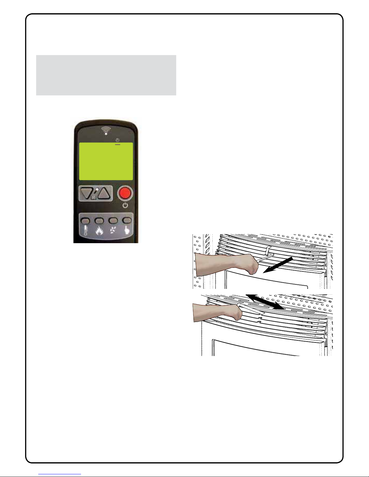
Press button [7] for 3-4 seconds to access the menus,
then use buttons [1] and [2] to scroll through the options,
and button [7] to Enter/Select.
The menus are as follows:
Menu 01 Set Clock
Menu 02 Set Crono (Programmable Thermostat)
Menu 03 Select Language
Menu 04 View Settings
Menu 05 State Stove (Fire Status)
Menu 06 Hours Work
Menu 07 Bank Data (protected by a password)
Menu 08 Reset Hours (protected by a password)
Menu 09 Default Settings (protected by a
password)
Menu 10 Select Recipe (protected by a password)
6.2 Menu One - Setting the Clock
To set the clock, proceed as follows:
1. Remove and reset the electric supply of the stove
using the general switch on the back.
2. The display will show FINAL CLEANING and then
OFF.
3. Press button [7]. (Menu 01 Set Clock will appear)
4. Press [7] to enter into this menu. DAY CLOCK will
appear:
5. Set the desired day by using [1] or [2] according to
the table shown below.
6. Press [7] to confirm
7. TIME CLOCK will appear on the display and the
current time will be shown. Change the hours of the
Display Meaning
01 Monday
02 Tuesday
03 Wednesday
04 Thursday
05 Friday
06 Saturday
07 Sunday
OFF Deactivated
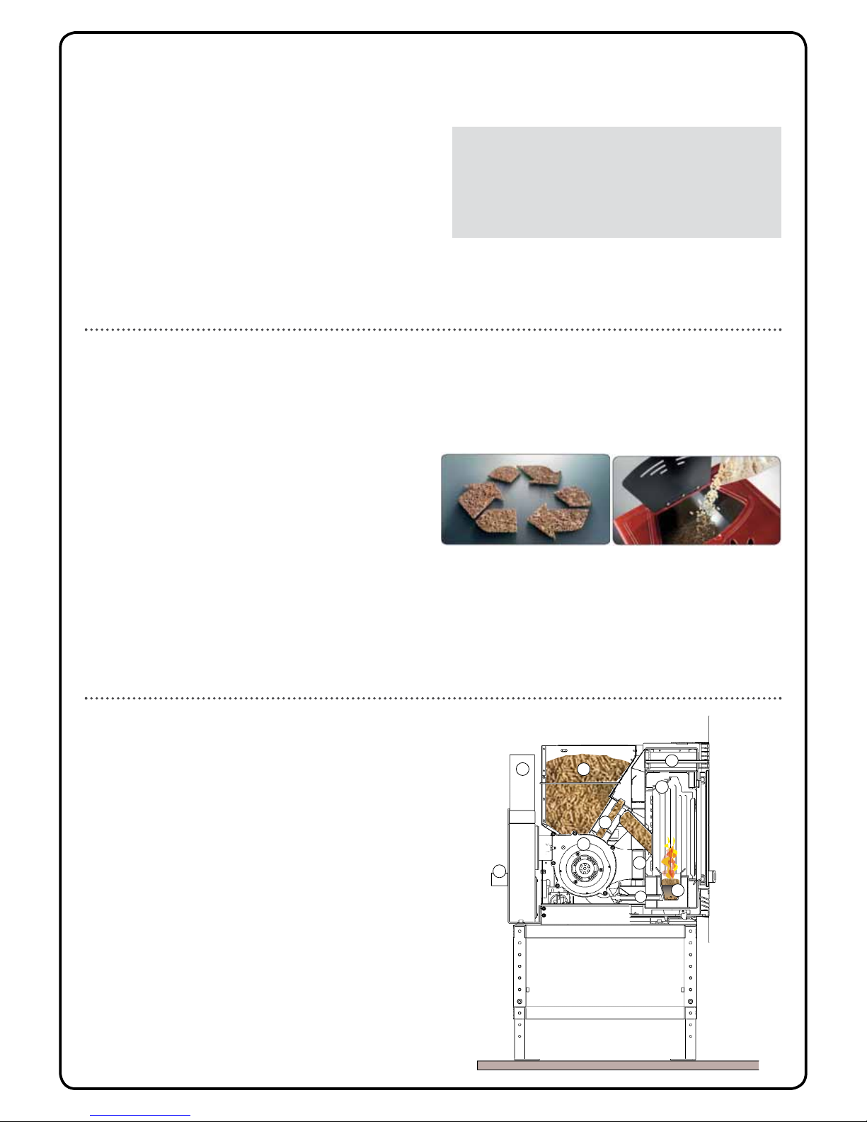
5.6 Operating Instructions
The heater is completely automated and will self-regulate
the ignition phase, five levels of power and the switching
off phase, guaranteeing safe functioning. The burn pot
used for combustion allows most of the ashes produced
by the combustion of the pellets to fall into the lower ash
pan. However, it is recommended that you check the burn
pot every day, as not all pellets have high standards of
quality and could leave residue that is difficult to remove.
A special air-circulation function facilitates self-cleaning
of the glass, however, a slight greyish film cannot be
avoided after a few hours of functioning.
Pellets with a diameter of 6mm, manufactured to the AS/
NZ 4014.6 or higher must be used with the stove.
5.7 Safety Devices
The heater is fitted with sophisticated safety systems
so that, in the case of breakage of one of the individual
parts or defects in the flue, no damage will be caused
to the stove and the room in which it is installed. In any
case, when a problem arises, the pellets stop falling
immediately and the switch off phase is activated. The
corresponding alarm will be shown on the display. The
details can be seen in the “7.1 Explanation of Alarms” on
page 12.
5.8 Operating Precautions
•In case of faulty operation turn the stove off pressing
button no. 3.
•Do not manually load the fire pot with pellets.
•Any build up of unburned pellets inside the fire pot
after repeatedly trying to light the stove, must be
removed before further attempts.
•Do not use any fuels other than wood pellets.
•Should the ignition system be faulty, do not attempt to
light the stove using flammable materials.
6. Setting up your pellet re

9
Page 7
day with [1] or [2] (24 hour clock) example: 4:30p.m
would be 16:30
8. Press [7] to confirm
9. MINUTES CLOCK will appear on the display.
Change the minutes of the day with buttons [1] or [2]
10. Press [7] to confirm
11. Press [3] to exit the menu
6.3 Menu Two - Set Crono
(Programmable Thermostat)
By using the built-in programmable thermostat you can
program your pellet fire to turn on/off automatically on
different days of the week, with two separate on/off times.
Example: Program 1. Start at 06:00 and Stop at 08:30;
Program 2, Start at 16:00 and Stop at 22:00.
To enter this menu, proceed as follows:
1. Press button [7] (Menu 01”Set Clock” will appear)
2. Press button [1] once you see (Menu 02 Set Crono)
3. Press button [7] to enter into this menu
4. Use Button [1] or [2] to set the time you want the
fire to start (time is in the 24 hour clock). Press [7]
to confirm
5. Use Button [1] or [2] to set the time you want the fire
to stop. Press [7] to confirm.
6. Now use [5] to scroll through the days you want the
fire to operate with this program and use [4] to set
the days to ON or OFF. Press [7] to confirm
7. Use [1] or [2] to set the power that you want the fire
run on (1- 5)
8. Press [7] to confirm.
9. Use [1] or [2] to set the room temperature that you
would like the fire to reach.
10. Press [7] to confirm
11. Repeat steps 4 through 10 to set program 2 (if
required)
12. Once you have completed setting up program 2
Press [3] to exit
Possible Settings
6.3.1 Modifications of the room temperature
setting
The hand held remote that controls the fire also has
a thermostat built in which measures the ambient
temperature. The room temperature will be shown on
the display. For the thermostat to control the pellet
fire’s heat output, the remote must be left in a suitable
place in the room where it can measure the typical room
temperature.
P - 3
PROG - 1
POWER
If this black line is not lit
up the timer function will
not be active. To activate
this line you must rst
set the day and time. See
“6.2 Menu One - Setting
the Clock” on page 8.
Description Values that can be set
START PROG -1 From OFF to 23.50 hours
STOP PROG -1 From OFF to 23.50 hours
DAY PROG -1 ON or OFF, Monday-Sunday
POWER PROG -1 From 1 to 5
TEMP ROOM PROG -1 From 7°C to 40°C
START PROG -2 From OFF to 23.50 hours
STOP PROG -2 From OFF to 23.50 hours
DAY PROG -2 ON or OFF, Monday-Sunday
POWER PROG -2 From 1 to 5
TEMP ROOM PROG -2 From 7°C to 40°C
UT06
08:30
PROGRAM 1
STOP
UT05
06:00
PROGRAM 1
START
Important: When using the Programmable
Thermostat mode, you must make sure that
after each time the stove is automatically
switched off, the burn pot remains clear in
order to guarantee correct automatic ignition.
A clean burn pot liner with all
the holes clearly visible
Burn pot liner needing cleaning
with holes blocked by ashes

10
Page 8
To set the desired temperature press button [4] then use
button [1] & [2] to achieve the desired value. When the set
temperature on the display is reached, MODULATION
WORK will appear on the screen and the fi re will drop to
its lowest power setting.
6.4 Menu Three - Select Language
(Setting the Language)
Some fi res may be in their default Italian language, if so
proceed with Instruction Set ‘A’.
If not, please use Instruction Set ‘B’.
A. Setting fire from Italian language to your desired
language. (English, German, French, Danish)
1. Press button [7] (Menu 01 “Set Orologio” will appear)
2. Press button [1] twice until you see (Menu 03 “Scegli
Lingua”)
3. Press [7] to enter into this menu (“Italiano Lingua”
should appear)
4. Press [1] or [2] until you see “English Lingua” or
select your desired language.
5. Press [3] twice to return to the main screen.
B. Setting fire from English language to your desired
language. (Italian, German, French, Danish)
1. Press button [7] (Menu 01 “Set Clock” will appear)
2. Press button [1] twice until you see (Menu 03 “Select
Language”)
3. Press [7] to enter this menu (“English Lingua” will
appear)
4. Press [1] or [2] to change to your desired language.
5. Press [3] twice to return to the main screen.
6.5 Menu Four - View Settings
In this menu you can check the values of the parameters
set in the control unit. This menu is used when a Service
Technician has to understand the parameters set in
the machine, to fi nd any modifi cations to improve the
functioning of the stove.
6.6 Menu Five - Stove State (Fire Status)
In this menu, you can check the correct functioning of
some of the key components of the pellet fi re.
To enter this menu either
1. Press Button [7] (Menu 01 “Set Clock” will appear)
2. Then press and hold [6] for 3 seconds
Or
1. Press [7] CLOCK SETTING MENU will appear
2. Press [1] four times “fi re State” menu, enter using
[7].
This menu is for use by a service technician for
commissioning and diagnostics, and for the customer
when loading pellets into the auger when the fi re has
been completely run out of fuel.
6.6.1 Loading the Screw (Auger)
Insert Models - Loading the Auger should only be
carried out in OFF mode
When the stove is new or the fi re has run out of fuel, the
auger will be empty. In this case it may be necessary to
‘load’ the auger so the fi re will start.
To load the screw/auger, proceed as follows:
1. Press Button [7] (Menu 01 “Set Clock” will appear),
The auger is activated
2000
150°
COCLEA 1
STATE
The auger is idle
2000
150°
STATE
COCLEA 0
2000
130°C
SCREW 0
STATE 1
Exhaust Fan RPM
Exhaust Temperature
Auger Status
1 = ON 0 = OFF
Stove Status
Note: DO NOT leave the remote down the side
of the sofa, on a window ledge or in a cold
draft, in another room, or in the flow of hot
air coming off the fire. These will give false
readings and the fire will not control the room
temperature correctly.

11
Page 9
then press and hold [6] for 3 seconds. The display
will show “SCREW STATE”.
2. Use Button [1] to turn the Auger On “SCREW 1” and
button [2] to turn it OFF.
3. Once started auger will run for a couple of minutes
4. Remember to turn the screw OFF (SCREW 0) with
button [2] before exiting, button [3]
5. Empty the burner pot of any pellets before starting
the fire
Also see “6.6 Menu Five - Stove State (Fire Status)” on
page 10.
6.7 Menu Six - Working Hours
The WORKING HOURS Menu shows the total run hours
done by the fire.
To enter this menu, proceed as follows:
1. Press Buttons [7] (Menu 01 “Set Clock” will appear).
2. Press button [1] twice until you see (Menu 06
“WORKING HOURS MENU.
3. Press [7] to enter this menu .
4. Press [3] to return to the main screen.
SCREEN DISPLAY DESCRIPTION
FINAL CLEANING The stove is switching off, the cooling phase is not yet completed
LIGHT The ignition phase has started,the pellets are loaded into fire pot
WAIT FOR FLAME The pellet’s are ignited by the hot air passing through the ignition
candle
FLAME PRESENT The flame is visible in the fire pot
WORK The stove has completed the switch ON phase; you can now
change the power
MODULATION WORK The set room temperature has been reached
T ON The room sensor is off or an external thermostat has been
connected
COOLING/WAITING FOR START The stove is cooling DOWN. When stove has cooled down it will
start automatically.
ON/WAITING FOR RESTART The switch ON phase, when the stove is warm, started. The
operation is same as phase ON
HOT SMOKE The max temperature of smokes is reached: to reduce
temperature, feeding pellets and air draft reduce at POWER 01
OFF The stove is off
6.8 Description of Screen Displays
7. Troubleshooting
In the event of a problem with the fi
re it will sound an
alarm and display a fault code and description, see
“7.1 Explanation of Alarms” on page 12 for more
information on the cause and what to do.
The fault can be cleared by pressing and holding button
[3] on the remote. Note which fault is displayed on the
screen before re-setting the alarm.
For basic faults follow the steps to resolve the problem
and
If
below). (see panel electronics
the above cap black the under located is This
work. willre fi the before re-set manually be to need
will device safety The . ALARM” “THERMAL display
and
device
safety
a
trip
will
this
hot
too
getsre fi
the
agent.service/
dealer
local
your
issues
complex
more
contact
For
re.fi
the
restarting
try
Unscrew
re. fi the restarting before trip to device safety
this for reason the ascertain you sure
Make
alarm. thermostat the reset to button
the press and cap protection the

12
Page 10
WARNING REASON SOLUTION
PELLETS FINISHED
ALARM
• The pellet hopper is empty • Check whether there are pellets in the hopper and refi ll if
necessary.
• The raio-motor does not load
pellets.
• Empty the hopper to check that no foreign objects have fallen
inside which could prevent the correct functioning of the
auger.
• Pellets not loading. • Contact local Service Technician
• IF THE PROBLEM CONTINUES, CONTACT YOUR LOCAL
SERVICE TECHNICIAN.
BLACK - OUT
• No electricity supply during
working phase. • Press the off button and repeat switching on the stove.
• IF THE PROBLEM CONTINUES, CONTACT YOUR LOCAL
SERVICE TECHNICIAN.
NO IGNITION ALARM
• The pellet hopper is empty • Check whether there are pellets in the hopper and refi ll if
necessary.
• Setting of pellets and of intake
during ignition phase insuffi cient • Contact local Service Technician.
• The ignitor is defective • Contact local Service Technician.
LOW FLAME ALARM
• The pellet hopper is empty • Check whether there are pellets in the hopper and refi ll if
necessary.
• Bad setting of pellet and air
during ignition • Contact local Service Technician.
FAN RPM ALARM
• The revolution of smoke fan
lowering more than 15% of speed
to fan congestion
• Contact local Service Technician.
FAN BROKEN ALARM
• Smoke extractor encoder is
not functioning or not correctly
connected
• Contact local Service Technician.
• No electricity supply to smoke
extractor • Contact local Service Technician.
• The smoke extractor is blocked • Contact local Service Technician.
DEPRESSION ALARM
• The combustion chamber is dirty • Follow the cleaning operations of the stove as per the
instructions manual.
• The fl ue is blocked • Check that the fl ue is clear and clean.
• The vacuum switch is
malfunctioning • Contact local Service Technician.
THERMAL ALARM WITH
RESET
• The thermostat with manual reset
has intervened
• Reset the thermostat pressing the button on the back of the
stove.
• The centrifugal fan is defective • Contact local Service Technician.
• Combustion in the fi re pot is not
optimal
• Switch off the stove, clean the fi re pot and regulate
combustion with the setting of the pellets.
HOT SMOKE ALARM
• Combustion in the fi re pot is not
optimal
• Switch off the stove, clean the fi re pot and regulate
combustion with the setting of the pellets.
• The centrifugal fan is defective • Contact local Service Technician.
• IF THE PROBLEM CONTINUES, CONTACT YOUR LOCAL
SERVICE TECHNICIAN.
SMOKE SENSOR ALARM
• The smoke sensor is
malfunctioning • Contact local Service Technician.
• The smoke sensor has been
disconnected from the board • Contact local Service Technician.
AUGER BLOCKED
ALARM • The auger does not load pellets • Contact local Service Technician.
7.1 Explanation of Alarms
ISPLAYDREASON SOLUTION
- Check
on turned is fire to supply power
firewith syncronised is remote
Remote in Batteries
position into pushed fully is fire
Check-
Check-
Check-
MAGNA
or
CERCA
CAMPO
CAMPO Sara/Camino
remote to
responding not is

13
Page 11
8. Maintenance and Cleaning
Before carrying out any maintenance take the following
precautions:
• Make sure that the general power supply has been
disconnected.
• Make sure that all parts of the wood pellet fi re are cold.
• Make sure that the ashes have cooled completely.
• Make sure that the general switch is in the zero
position (off).
• Make sure that the plug is disconnected from the
socket, thus avoiding accidental electric shocks.
• Always use appropriate tools for maintenance.
• When you have fi nished re-install all safety guards
before using the wood pellet fi re again.
The wood pellet fi re requires little maintenance if quality
wood pellets are used which is why we recommend
pellet fuel that is manufactured to the AS/NZS 4014.6.
The following list of components should be inspected
and maintained routinely to ensure that your pellet fi re
is operating optimally and giving you the best effi ciency.
IMPORTANT: the fire should be cold and the
plug removed from the power supply for any
maintenance.
NOTE: Do not use abrasive or solvent based
cleaners to clean any part of the pellet fire.
Parts/Frequency 1 Day 3-5 Days 30 Days Yearly Performed By
Burn pot • Owner
Ashpan • Owner
Firebox and fl ame trap • Owner
Door Glass • (or as required) Owner
Seals & Gaskets • Owner/Technician
Pellet Hopper • Owner/Technician
Fresh Air Intake • Owner/Technician
Blower Mechanisms • Technician
Fire exhaust passages • Technician
Flue system • Technician
Frequency recommendations given are based on typical
fi re performance and maybe shorter or longer dependent
on fuel quality, fi re performance and run hours.
Your pellet fi re burns solid fuel and as such requires
servicing by a qualifi ed person at least once a year -
generally over the summer or at the start of the season.
The purpose of this maintenance is to make sure that the
fi re is in good working order and is safe and ready for the
heating season.
We recommend you draw up an annual contract for
maintenance of the fi re with your installer/dealer.
8.1 Burn Pot Liner (daily)
This is the ‘pot’ where the pellets are burned. The burn
pot liner should be inspected every time you start the fi re
(when the unit is cold), to ensure all the holes are free to
allow correct air fl ow for combustion. Failure to keep the
bun pot liner clean may cause a build-up of fuel above
the burn pot liner and up the pellet feed tube. This will
cause the auger to jam and may result in pellets burning
in the pellet feed tube and hopper. Keeping the burn pot
liner clean will help avoid possible overheating, which
could cause changes in the colour of the paint, as well
as ignition failures.
For light deposits the burn pot liner can be scraped out
in situ with the scraper tool provide. For heavier deposits
and thorough weakly cleaning it should be removed.
Combustion chamber
Fire pot
Fire pot grill
Scraper

14
Page 12
To remove the burn pot liner, open the door and lift the
burn pot liner from the burn pot holder.
Using the metal scrapper or suitable tool (wire brush)
remove material that has accumulated in the burn
pot liner or is clogging the holes, then dispose of the
scrapped ashes . Place the burn pot liner back into burn
pot holder, making sure that the igniter hole is aligned
with the igniter tube, then push the burn pot liner back up
against the igniter tube.
8.2 Heat Exchanger Tubes (daily)
The handle for the heat exchanger cleaning rod is pointed
out in the fi rst image below. This handle is to be pulled
back and forth a few times (ONLY WHEN THE UNIT IS
COLD) in order to clean away any fl y ash that may have
collected on the heat exchanger tubes. As different types
of pellets produce different amounts of ash, cleaning of
the tubes should be done on a regular basis to enable
the unit to run effi ciently. Use the supplied scraper tool to
access the handle.
8.3 Firebox, Flame Trap, Burn Pot
Holder and FIREX Lining (3-5 days)
Dependent on fi re use and fuel quality, the insides of the
fi re box should be cleaned out once every 3-5 days. This
includes the burn pot holder.
To do this lift the burn pot liner from the fi re and clean out
the burn pot holder of ash - the easiest way of doing this
is to vacuum it out. Make sure the air intake is clear of
ash or debris - this can also be vacuumed out to ensure
it is clean.
Place the burn-pot back into the fi re, making sure that
the burn pot is located correctly.
The Flame Trap located in the top of the burn chamber,
below the heat exchanger tubes, should be removed and
the ash which has been scraped off the heat exchanger
tubes cleaned off. The heat exchanger tubes can also be
brushed clean with a soft brush.
All Ravelli products have a combustion chamber made
with FIREX 600, a material based on vermiculite, the
result of research and development by Ravelli . The
main features of FIREX 600 are resistant to heat, its
lightness and excellent insulating capacities, improving
Note: If after long periods of burning, the flame
is a tall, lazy flame with dark orange tips and
the fire builds up and overflows the burn pot
or there is a build-up of clinkers, this is an
indication that fire may need to be shut down
and cleaned.
CAUTION: BECAUSE THE FLY ASH IS VERY
FINE, THE USE OF A BAGGED VACUUM
CLEANER IS RECOMMENDED. BAG-LESS
VACUUMS CAN BE DAMAGES BY THE FINE
ASH. Please pay special attention that there
are no hot ashes or there could be a possibility
of a fire hazard inside the vacuum cleaner.
Place all hot ashes into a non-combustible
container.
FRONT
RIGHT HAND SIDE
LEFT HAND SIDE
FLAME TRAP
A clean burn pot liner with all
the holes clearly visible
Burn pot liner needing cleaning
with holes blocked by ashes

15
Page 13
the combustion and performance of the fi re.
During combustion,
FIREX 600 turns
white, due to an effect
called PYROLYSIS,
making the fl ame
clear and shining.
If the combustion is
regulated correctly,
the FIREX 600
interior always
remains clean and white.
The condition of FIREX 600 is therefore a gauge to
understanding whether the combustion is good or not.
FIREX 600 LIGHT - EXCELLENT COMBUSTION
FIREX 600 DARK - POOR COMBUSTION
FIREX 600 does
not require special
maintenance, it only
has to be dusted with
a brush to remove the
ash that is deposited
during combustion.
Abrasive sponges
should not be used as
they could compromise the thickness of the FIREX600
panel.
The tube of the vacuum cleaner should not be used in
direct contact with FIREX 600.
Wet cloths should not be used to clean FIREX 600.
FIREX 600 is resistant to heat but can still break; handle
with care.
FIREX 600 may show a slight abrasion after a few hours
of functioning, this is perfectly normal as the fl ame
creates microgrooves in the panel without compromising
it.
The duration of FIREX 600 depends only on how
maintenance is carried out.
8.4 Ash Pan (3-5 days)
Monitor the ash level every week. Remember that
different pellet fuels will have different ash contents.
Ash content is a good indication of fuel effi ciency and
quality. Refer to “Warnings and Recommendations” for
disposal of ashes. DO NOT PLACE UNBURNED OR
RAW PELLET FUEL IN THE ASH PAN. Vacuum the ash
pan and inside the pedestal.
8.5 Door Glass (3-5 days or as required)
The fi re is designed to keep the glass as clean as
possible while the fi re is in operation, a fl ow of air runs
along the surface of the glass keeping ash and dirt away.
However, a greyish patina will form after a few hours. A
poorly performing fi re will get brown or black deposits on
the glass.
The glass must be cleaned only when the fi re is cold,
using a damp cloth or kitchen paper. Sometimes it is
best to dirty the cloth slightly with ash from the fi re itself
to create a slightly abrasive action which will help to
remove stubborn deposits.
The door glass is made of special high temperature
PYROCERAMIC. The use of substitute materials is
prohibited use only offi cial Ravelli replacement parts
8.6 Seal & Gaskets (monthly)
Regularly check the condition of the door seals, gaps
or damaged / loose seals may cause a loss of vacuum
in the burn chamber and result in poor combustion. To
repair or replace this, glue the gasket on, using high
temperature fi berglass gasket glue see your local dealer
for details.
8.7 Pellet Hopper (monthly)
The quality of the pellets being used is very important
as this affects the heat output of the fi re and the
cleaning requirements. Fuel quality can vary between
manufacture and even between batches from the same
manufactures. If you have an excess of fi nes (sawdust)
in the bag this builds up in the bottom of the hopper
and can jam the auger over time. We recommend that
once a month you run the fi re out of fuel and vacuum
any accumulated fi nes (sawdust) from the bottom of the
hopper to prevent any issues.
8.8 Fresh Air Intake (yearly or as
required)
Inspect periodically to be sure that it is not clogged with
any foreign materials.
8.9 Flue System (yearly)
The products of combustion will contain small particles
of fl y ash. The fl y ash will collect in the fl ue system and
restrict the fl ow of the fl ue gases. Incomplete combustion,
such as occurs during start up, shutdown, or incorrect
operation will lead to some soot formation which will
also collect in the exhaust venting system. The exhaust
NOTE: Do not attempt to light the fi re if the glass
is broken.

16
Page 14
venting system should be inspected and cleaned at
least once every year or after every ton of pellets burnt.
We recommend contacting your dealer for professional
cleaning. To remove dust from the vent pipe, tap lightly
on the pipe to dislodge any loose ash. Open the bottom
of the flue adapter box and vacuum as much of the ash
out of the vent pipe as possible.
8.10 Blower Mechanisms (yearly)
Pull the fire forward to access the two blowers. Vacuum
all dust from motors and convection fan blades. DO
NOT lubricate these fans they have sealed bearings.
8.11 Post season clean-up
Once you are finished using the pellet appliance for the
season, unplug the fire for added electrical protection. It
is very important that the fire be thoroughly cleaned and
serviced as stated above. Exposed metal part may be
painted with high temperate paint to prevent rusting over
the off season.
8.12 Cleaning the surfaces
To clean the surfaces on the painted metal parts, use a
damp cloth.
Important: the use of aggressive detergents or
abrasive cleaners can damage the surfaces of the
stove.
1.1 Dimensions (Ravelli Sara)
Height 542mm
Width 610mm
Depth 590mm
Weight 105kg
Diameter of smoke exhaust 80mm
Min - Max calorific power 3.7Kw/h - 6.6Kw/h
Min - max hourly consumption of pellets 0.8kg/h - 1.6kg/h
Electrical power absorbed during operation 240W
Supply 220V - 50Hz
Hopper Capacity 15kg
Space Heating Efficiency 82%
The data shown are indicative and not binding.
Ravelli reserves the right to make any
modifications for the purpose of improving the
performances of the product.

17
Page 16
9. Maintenance Record
ERU T ANG I STUODE I RRACKROWE T AD

18
Page 17
10. Warranty Information
Pellet SolutionsF i r e and its partner Ravelli ,
manufacturers of the Ravelli range of pellet fires
extends the following warranty for their wood pellet fires
when purchased from an authorised Pellet
Solutions
F i r e
dealer.
10.1 Warranty Coverage
Pellet SolutionsF i r e warrants to the original owner of
the pellet fire at the site of installation, and to any
transferee taking ownership of the pellet fire at the
original site of installation within two years following the
date of original purchase, that the pellet fire will be free
from defects in materials and workmanship at the time of
manufacture. After installation, if any covered components
manufactured by Ravelli are found to be defective in
materials or workmanship during the applicable warranty
period, Pellet SolutionsF i r e will, at its option, repair or
replace the covered components. Pellet SolutionsF i r e , at
its own discretion, may fully discharge all of its
obligations under such warranties by replacing the
product itself or refunding the verified purchase price of
the product itself. The maximum amount recoverable
under this warranty is limited to the purchase price of
the product. This warranty is subject to conditions,
exclusions and limitations as described below.
This warranty only covers pellet fires that are purchased
and installed through an authorised Pellet SolutionsF i r e
dealer or distributor. A list of authorised dealers is
available on the Pellet SolutionsF i r e website
(www pelletfiresolutions. .co.nz).
This warranty is only valid while the pellet fire remains at
the site of original installation.
Contact your installing dealer for warranty service. If the
installing dealer is unable to provide necessary parts,
contact the nearest authorised Pellet SolutionsF i r e
dealer or supplier. Additional service fees may apply if
you are seeking warranty service from a dealer other
than the dealer from whom you originally purchased the
product.
Check with your dealer in advance for any costs to you
when arranging a warranty call. Travel and shipping
charges for parts are not covered by this warranty.
10.2 Warranty Period
Warranty coverage begins at the date of installation. In
the case of new home construction, warranty coverage
begins on the date of first occupancy of the dwelling, or six
months after the sale of the product by an independent,
authorised, Pellet SolutionsF i r e dealer/distributor,
whichever occurs earlier. The warranty period for parts
and labour for covered components is explained in
the following table.
Component(s) Parts Period Comments
Fireplace,
stovebody and
parts covering:
Firebox, firebox
panel, & burnpot
Heat exchanger
Pedestals,
Panels & Legs
Full
replacement
5 years
parts
2 years
labour
Surface
finishes,
burnpot liner
and ceramic
panels are
covered
separately (see
clarifications
and exclusions
below).
Electrical items covering
Ignitor (including
tube)
Auger Motor
Circuit Board,
decal & mounting
bracket
Blowers
(Convection and
Combustion)
Timers
Sensors
Vacuum Switch
Wire harness
Full
replacement
2 years
parts &
labour
Replacement/spare Parts
All replacement
parts beyond
their original
warranty period
or purchased
new from a
Dealer
Full
replacement
1 year
parts only
Evidence of
the original
purchase date
will be required
e.g. a copy of
the original
invoice.
Clarifications and exceptions
Burnpot Liner
and Brick Liner
Full
replacement
1 years
parts &
labour
Paint on the
brick firebox
lining may peel
over time due
to the extreme
conditions and
is not a flaw.
Exterior
surface finishes
(including plating,
enamel or paint)
Full
replacement
1 years
parts &
labour
Colour changes
with heating
and tarnish,
discolourisation
and wear
(including
scratches,
fingerprints etc.)
are not covered
under warranty.
Exclusions
Glass No warranty
Vermiculite (Firex
600) & ceramic
panels (cast
majolica)
No warranty
Fibreglass rope
gaskets
No warranty
Other manuals for Sara
2
Table of contents
Other Ravelli Indoor Fireplace manuals
Popular Indoor Fireplace manuals by other brands

Nordpeis
Nordpeis Quadro Colorado Exclusive Erratum of installation and user manual

Tulikivi
Tulikivi P10 operating manual

Heatilator
Heatilator Novus NDV3630 owner's manual

Travis Industries
Travis Industries Xtrordinair 44 Elite installation manual

BFM Europe
BFM Europe Passion Series Installation, maintenance & user instructions

Reversi
Reversi SUPREME DVD-400 N operating instructions