Table of Contents
CHAPTER 1 INTRODUCTION ...............................................................................1
General Information ...................................................................... 1
Safety Warning ............................................................................... 1
Raven Electronics’ Warranty ........................................................ 1
System Description......................................................................... 2
FCC Part 68 Information................................................................2
CHAPTER 2 INSTALLING and SETTING UP THE SNI SHELF................................4
Equipment Needed for Installation ............................................. 4
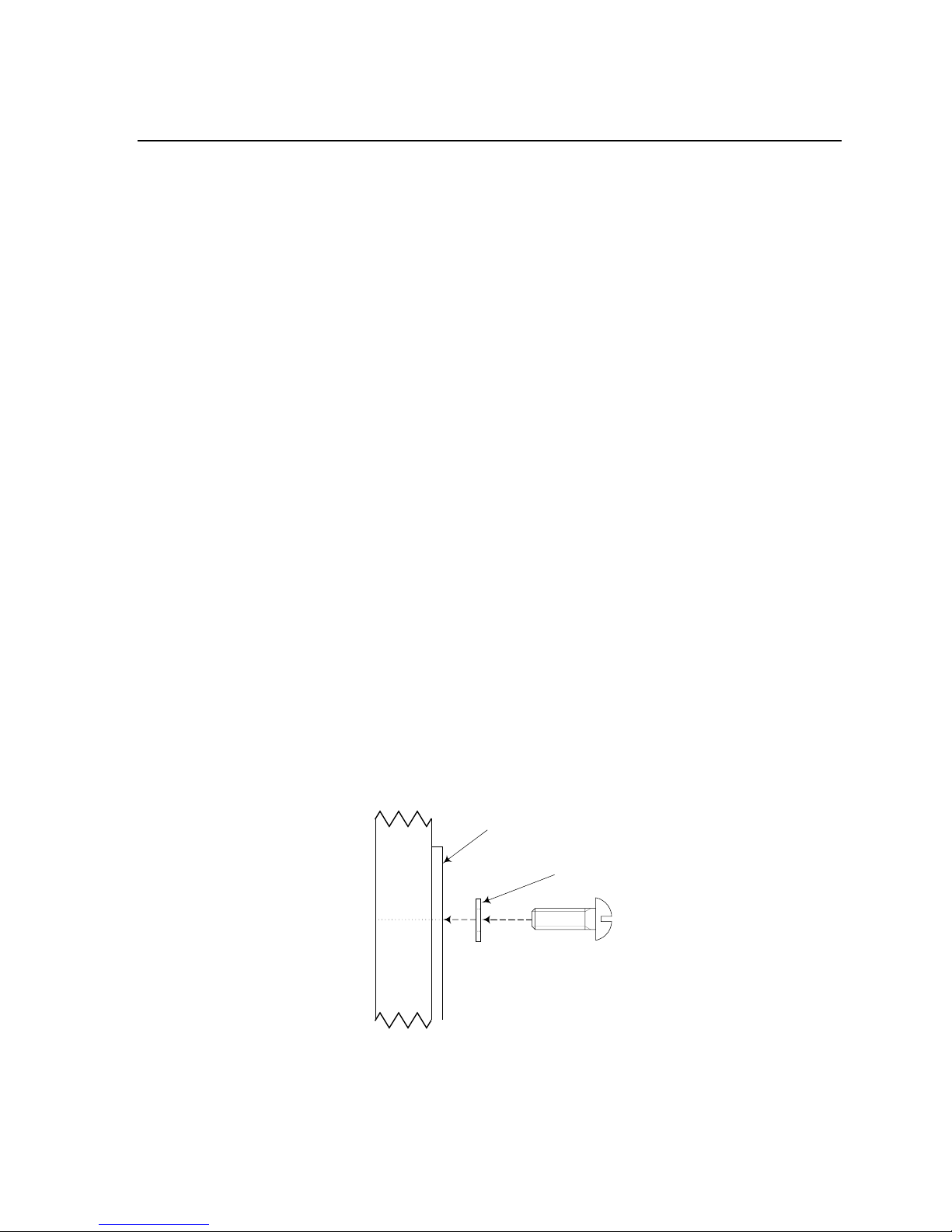
Mounting Unit in Rack ................................................................... 4
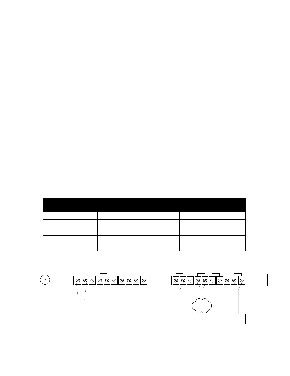
Hooking Up Connections.............................................................. 5
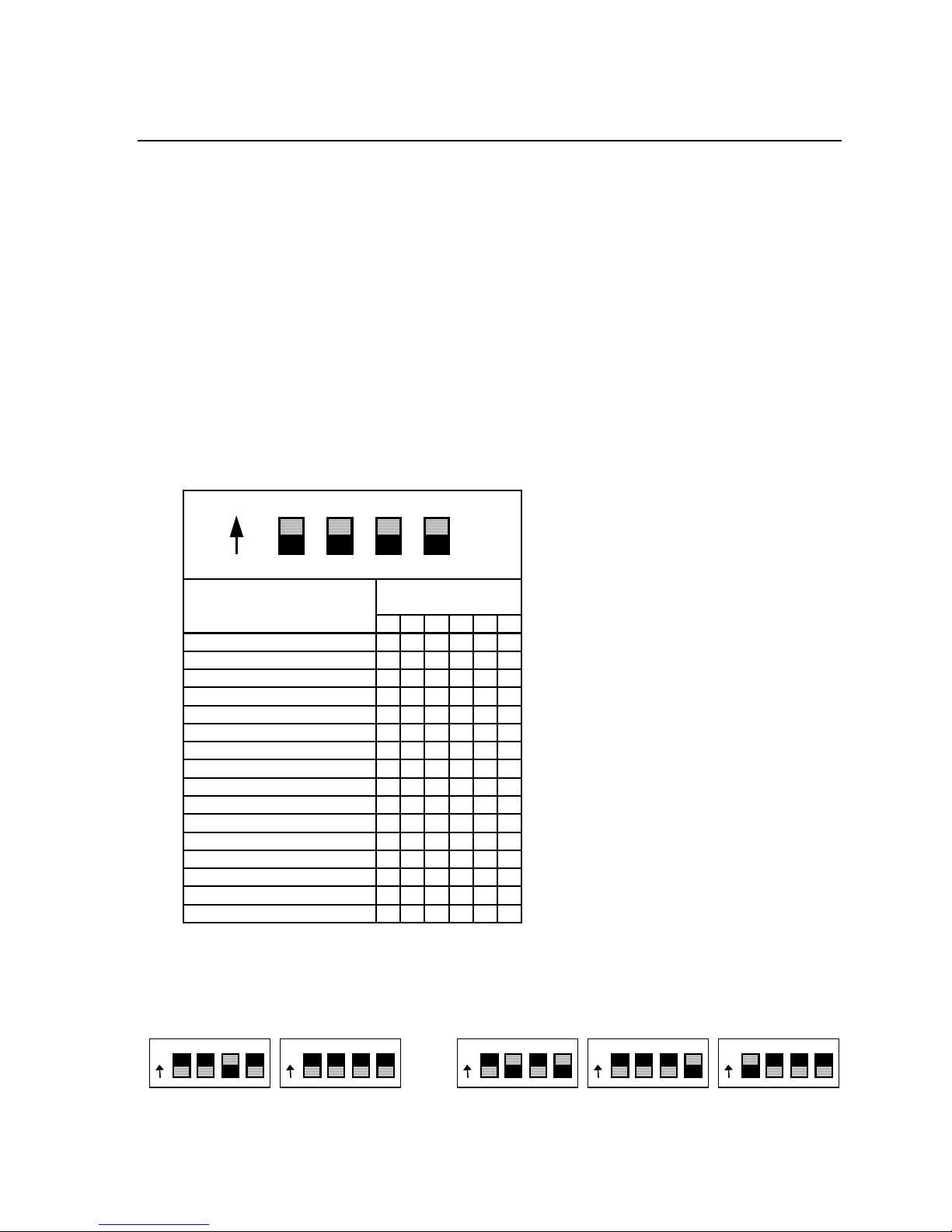
Programming the DTMF Address Decoder ................................ 6
CHAPTER 3 POWERING UP THE SNI SHELF.........................................................7
CHAPTER 4 OPERATION...................................................................................... 8
Accessing the PSTN or PABX......................................................... 8
Accessing the Service Channel Network from PSTN or PABX .8
Ending a Call .................................................................................. 8
CHAPTER 5 TROUBLESHOOTING and ALIGNMENT ..........................................9
Equipment Needed for Troubleshooting and Alignment ........9
41675 Switched Network Interface ............................................. 9
41632 DTMF Address Decoder ...................................................11
41620 Power Supply.....................................................................11
CHAPTER 6 SPECIFICATIONS............................................................................12
TABLE A DIAGRAMS.....................................................................................13
Back Panel Diagram....................................................................13
40710D-600 Wiring Diagram .......................................................14
41620 Power Supply Block Diagram.......................................... 15
41632 DTMF Address Decoder Block Diagram........................16
41675 Switched Network Interface Block Diagram ................17
TABLE B INSTALLER CONNECTIONS ...........................................................18
APPENDIX A OPTIONS.........................................................................................19
APPENDIX B GENERAL CONDITIONS OF SALES ...............................................20
i