RavensBlight THE CRIMSON MONARCH User manual

THE CRIMSON MONARCH – Assembly Instructions Page 1.
(Continued on next page...)

THE CRIMSON MONARCH – Assembly Instructions Page 2.
WHAT YOU'LL NEED: Sci or , Elmer' glue (or a glue tick), a ruler or other traight-edge, and a black marker. A
mall utility knife i helpful but not e ential.
FOLDING TIP: I recommend ' coring' the fold line before folding. You can u e an old ink pen, a knitting needle, the
end of a paper clip, or any metal object that will make a crea e on the fold line without tearing the paper. Scoring will
help you fold much more quickly and preci ely.
BUILDING TIPS: The in truction will often ay 'trim a needed'. There are two way to trim a part. One method i to
cut away any unwanted white paper. The other method i to u e the black marker to black out any white paper. U e
whichever method eem be t in each in tance.
And for an extra nice model, u e the black marker to darken the fold line after coring, and to darken the edge of the
paper on each part (by laying the marker' tip ideway on the paper edge, or by laying the piece down and tracing
around it with the marker.)
ASSEMBLY: Begin by cutting out the FUSELAGE FRONT on Part Page 1. U e the utility knife to remove
the white rectangular area in the top panel. Fold the gray tab DOWNWARD and then fold DOWNWARD
between all ix panel . Glue the gray tab to the unprinted ide of the oppo ite panel, forming a piece like the
one hown in Figure 1.
(Continued on next page...)

THE CRIMSON MONARCH – Assembly Instructions Page 3.
Next, cut out the FUSELAGE REAR on Part Page 1. Fold the ix rectangular tab DOWNWARD, fold the
gray triangular tab DOWNWARD, and then fold DOWNWARD between all ix panel . Glue the gray
triangular tab to the unprinted ide of the oppo ite panel, forming a piece like the one hown in Figure 2.
Connect the FUSELAGE REAR to the FUSELAGE FRONT by gluing the rectangular tab (on the rear
piece) directly over their matching area (on the front piece.) Begin by gluing the top panel (the one with a
ga cap), then the bottom panel, and fini h by gluing the ide panel . The FUSELAGE hould now re emble
Figure 3.
Cut out the ENGINE on Part Page 1. Four of the gray tab have a red edge. Cut along the red edge to
eparate the tab from their adjoining panel . Fold all ix gray tab DOWNWARD. Fold the ix outer
rectangular panel DOWNWARD, fold all ix ide panel DOWNWARD and then fold DOWNWARD
between the connected ide panel . Glue the four triangular gray tab to the unprinted ide of the center
panel. Glue the two remaining gray tab to the unprinted ide of the adjoining ide panel to form a piece
like the one hown in Figure 4.
Add the ENGINE to the FUSELAGE FRONT in the ame manner a we did the FUSELAGE REAR. Start
with the top panel (with the machine gun barrel ), then glue the bottom panel and fini h by gluing the ide
panel . The FUSELAGE hould now re emble Figure 5.
Now cut out the COCKPIT on Part Page 1. Fold the two gray tab UPWARD. Fold UPWARD between the
two eat panel , and fold the two ide panel UPWARD, folding along the green line . Then fold the front
panel (with machine gun ), the rear panel and the two mall ide tab DOWNWARD, folding along the blue
line . Glue the two gray tab to the unprinted ide of the ide panel a hown in Figure 6. Place the
COCKPIT into the FUSELAGE a hown in Figure 7. Glue the front panel, rear panel and ide tab to the
fu elage.
The fu elage i now fini hed and we can tart adding wing ! Cut out the LOWER WING on Part Page 2.
Don't eparate the two ide , ju t cut along the outer rectangle (thi need not be very preci e) and then fold
DOWNWARD in the center (being very preci e). Glue the two halve together and then cut out the wing.
Trim a needed.
Glue the panel with a yellow dot to the matching panel on the fu elage bottom, a hown in Figure 8.
Cut out the CENTER WING on Part Page 2 and a emble in the ame manner a we did the LOWER
WING. Glue the center area (with machine gun ) directly over the matching area of the fu elage, a hown
in Figure 9.
Cut out the UPPER WING on Part Page 3 and a emble in the ame manner a we did the other two
wing .
The cut out the UPPER WING BRACE on Part Page 4. Fold the two outer ide panel DOWNWARD along
the blue line and glue them to the unprinted ide of the matching inner ide panel . Then fold the two
rectangular tab UPWARD along the green line and fold UPWARD along the green line on both ide of
the center panel.
If you want, you can now u e a mall utility knife to carefully remove the black triangle in the two ide
panel and trim a needed. If you'd rather not bother, the black triangle can be left in place.
(Continued on next page...)

THE CRIMSON MONARCH – Assembly Instructions Page 4.
Flip the UPPER WING up ide down ( o the two gray rectangle with green dot are howing) and glue the
two rectangular panel on the UPPER WING BRACE to the two gray panel on the UPPE WING, a hown
in Figure 1O. Be ure the machine gun are facing toward the front of the wing, a hown in Figure 11.
Glue the UPPER WING BRACE center panel directly over the matching panel on the fu elage, a hown in
Figure 12.
Next, we need to brace the wing . Cut out the two LEFT WING BRACES on Part Page 4. For each of the e
two brace , fold DOWNWARD along the blue line and glue the two ide together. Trim a needed. Then
fold the two quare bracket on each brace UPWARD along the green line . Place a bracket between the
LOWER WING and the CENTER WING, on the left ide of the fu elage. Glue the two bracket to the
matching bracket on the wing , a hown in Figure 13. Repeat thi proce to add a wing brace between
the CENTER WING and the UPPER WING, again on the left ide of the fu elage.
Now cut out the two RIGHT WING BRACES. A emble them in the ame manner a before, and connect
them to the wing on the right ide of the fu elage.
Next, cut out the FRONT LANDING GEAR on Part Page 3. Fold UPWARD along the ix green line . Fold
DOWNWARD along the three blue line . Glue the triangular ide ection to the unprinted ide of their
matching panel . Once again, you can u e a mall utility knife to remove the black inner triangle , or you
can leave them in place. Trim a needed.
Now glue the printed ide of the gray tab to the unprinted ide of the large oppo ite panel, lining up the gray
tab with the oppo ite panel' fold line. The piece hould re emble Figure 14. Fold the two large panel
together and glue. Trim a needed.
Glue the unprinted center panel to the gray area with a red dot on the bottom of the fu elage, a hown in
Figure 15.
Now we'll need to brace the FRONT LANDING GEAR o it hold it' form. Cut out the LEFT BRACE on
Part Page 3. Fold DOWNWARD along all three blue line . Glue the large center panel together and trim
a needed. Glue the large tab (with a bolt) to the matching area on the left bottom of the landing gear. Glue
the remaining LEFT BRACE tab to the ide of the landing gear, a hown in Figure 16.
Cut out the RIGHT BRACE on Part Page 3, a emble it in the ame manner a the left brace, and add it to
the right ide of the landing gear.
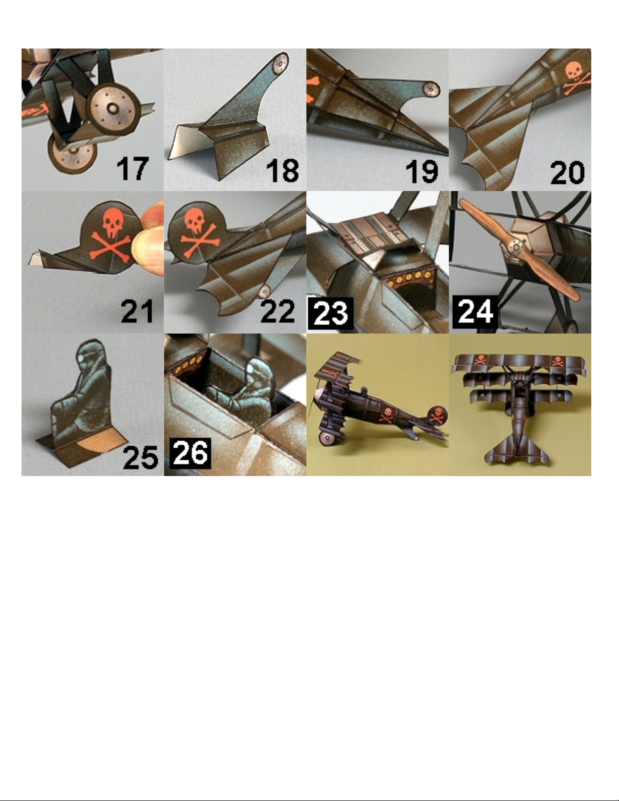
Now cut out the WHEELS on Part Page 5, cutting along the outer black line . Fold DOWNWARD in the
middle, glue the two ide together, and then cut out the two wheel . Trim a needed.
Glue a wheel to each ide of the LANDING GEAR, gluing the gray rectangle on the wheel to the unprinted
rectangle on the landing gear, a hown in Figure 17.
Next, cut out the LEFT REAR LANDING GEAR and the RIGHT REAR LANDING GEAR on Part Page 2.
For each piece, fold UPWARD along the green line and then fold DOWNWARD along the blue line. After
folding both piece , glue the lower ection together a hown in Figure 18 and trim a needed.
Place the rear landing gear over the gray area on the bottom of the rear fu elage, a hown in Figure 19,
and glue in place.
Now cut out the HORIZONTAL STABILIZER on Part Page 4. Fold UPWARD along the two green line and
then fold DOWNWARD along the two blue line .
(Continued on next page...)

THE CRIMSON MONARCH – Assembly Instructions Page 5.
Cut out the two HORIZONTAL STABILIZER BOTTOM piece on Part Page 4 and glue them to the
unprinted ide of the matching panel on the HORIZONTAL STABILIZER (being ure the in ide edge of
each bottom piece doe not extend beyond the fold line on the horizontal tabilizer). Trim a needed. Then
place the HORIZONTAL STABILIZER over the matching area on the rear fu elage, a hown in Figure 20,
and glue in place.
Cut out the LEFT FIN and RIGHT FIN on Part Page 4. For each fin, fold UPWARD along the green line and
then fold DOWNWARD along the blue line.
Glue the two fin piece together (gluing only the large panel ) a hown in Figure 21. Trim a needed. Place
the FIN in po ition over the matching panel on the rear fu elage, a hown in Figure 22, and glue in place.
Next, cut out the WINDSHIELD on Part Page 5. Fold the large gla ection UPWARD along the green line
and then fold the two ide window DOWNWARD along the blue line . If you want, you can darken the
unprinted ide of the gla ection with a pencil or marker. Po ition the machine gun over the matching
panel on the fu elage and glue in place a hown in Figure 23.
All we need to fini h the aircraft i a propeller. Cut out the PROPELLER on Part Page 5, cutting along the
outer black line . Fold DOWNWARD along the center line and then glue the two ide together. Cut out the
propeller and trim a needed. Glue the center of the propeller to the center of the engine' front panel, a
hown in Figure 24.
Although the aircraft i now fini hed, the model will be much more intere ting if you add a pilot. Cut out the
two PILOT piece on Part Page 5. Fold the eat panel UPWARD along the green line . Glue the two pilot
panel (but not the eat panel ) together, a hown in Figure 25. Trim a needed. Place the pilot in the
COCKPIT and glue the pilot' eat panel to the cockpit eat, a hown in Figure 26.
Congratulation ! Your model of the dreaded Crim on Monarch fighter plane i now complete.
Table of contents
Other RavensBlight Toy manuals
Popular Toy manuals by other brands

Mattel
Mattel Mega Bloks TARTARUGA manual

Hasbro
Hasbro KRE-O CityVille INVASION SKYSCRAPER MAYHEM... manual

Eduard
Eduard CVN-65 Enterprise Part4 quick start guide

Hasbro
Hasbro Littlest Pet Shop Whirl Around Playground manual

Crooza
Crooza DBX - 4x4 Operation manual

Fisher-Price
Fisher-Price GLN18 quick start guide

Jamara
Jamara Garant Fasswagen instructions

project mc2
project mc2 BATH FIZZ EXPERIMENT quick start guide

Hornby
Hornby BRITANNIA CLASS 7MT Operating and maintenance instructions

Faller
Faller 144022 manual

Artec
Artec Robo Bipedal T. REX Assembly instructions

Eduard
Eduard Zoom Victor B Mk.2 (BS) quick start guide