Raveon Technologies Corporation WayWORD User manual

Mobile Data Terminal
WayWORD
Mobile Data Terminal
and
GPS Tracking System
Technical and User Manual
Proposal for
December 2014
Version A5

2
Raveon Technologies Corp.
Company Confidential, 04/2013
Raveon Technologies Corporation
2320 Cousteau Court
Vista, CA 92081–USA
+1-760-444-5995
www.raveon.com
Table of Contents
1Overview.....................................................................................................................4
1.1 General .................................................................................................................4
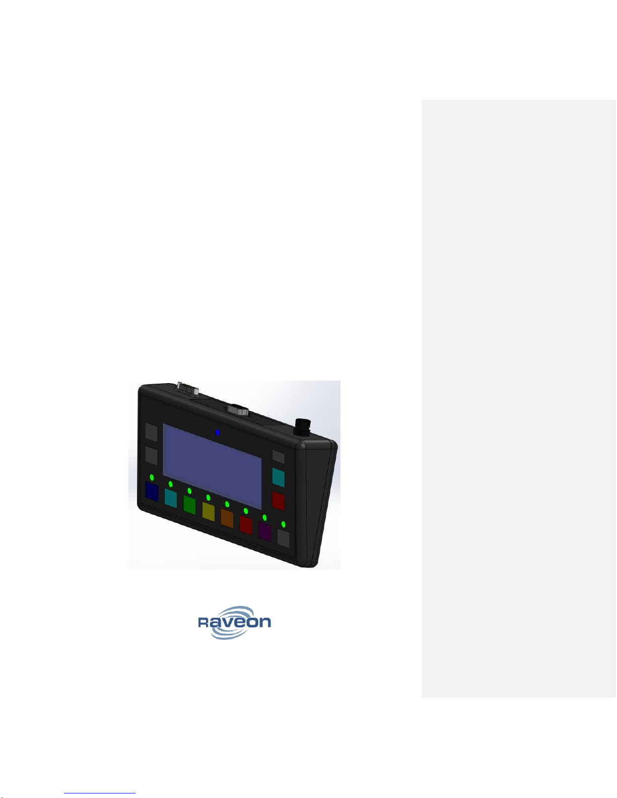
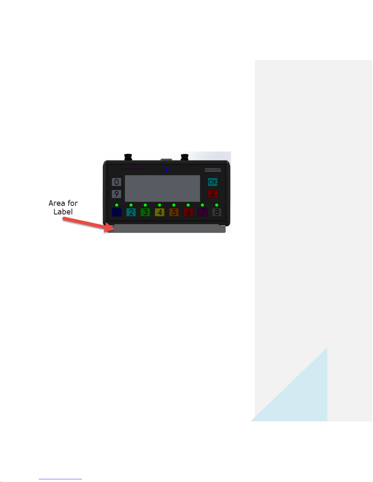
2WayWORD Mobile Data Terminal.............................................................................5
3Operating the WayWORD...........................................................................................6
3.1 Receiving Text Messages.....................................................................................6
3.2 Sending One-Button Status Messages.................................................................6
3.3 Sending Two-Digit Event Codes ...........................................................................6
3.4 Entering the UI Menu............................................................................................6
3.5 Backlight Level......................................................................................................7
3.6 Button................................................................................................................7
3.7 X Button ................................................................................................................7
3.8 Function Button.....................................................................................................7
3.9 Operator ID ...........................................................................................................7
4System Setup and Configuration.................................................................................7
4.1 GPS Tracking Systems.........................................................................................7
4.2 Messaging Only Systems without GPS tracking ...................................................8
5Text Messaging Protocol.............................................................................................8
5.1 ASCII Codes .........................................................................................................8
5.1.1 Text.................................................................................................................8
5.1.2 Control Characters .........................................................................................9
5.1.3 Parameters...................................................................................................10
5.1.4 End of Message............................................................................................11
5.2 Status Button Messaging ....................................................................................11
5.3 Text message Format.........................................................................................11
6Inputs and Outputs....................................................................................................12
6.1 DC Power............................................................................................................12
6.2 Digital Inputs and Outputs...................................................................................13

3
Raveon Technologies Corp.
Company Confidential, 04/2013
6.2.1 Pin-out:.........................................................................................................13
6.3 Connector Wiring ................................................................................................14
6.4 RS232 Serial Interface........................................................................................14
6.5 Command Mode..................................................................................................15
6.6 Setting a Parameter............................................................................................15
6.7 Configuration Commands ...................................................................................16
7Radio Modems..........................................................................................................17
7.1 RV-M7 Series GPS Transponders......................................................................17
7.2 RV-M7-VB-WX weatherproof transponders ........................................................17
8RavTrack PC.............................................................................................................18
8.1 Client Workstations.............................................................................................18
8.2 RavTrack PC MDT Features:..............................................................................18
8.3 Configuring RavTrack PC for Text Messaging....................................................18
8.4 Configure the IO Profile.......................................................................................19
9Mounting...................................................................................................................21

4
Raveon Technologies Corp.
Company Confidential, 04/2013
1 Overview
1.1 General
This manual describes the features and options of theWayWORD RV-DT-8R Mobile
Data Terminal (MDT). It also includes a section describing how the MDT’s features are
utilized within Raveon’s RavTrack PC GPS tracking and messaging application.

5
Raveon Technologies Corp.
Company Confidential, 04/2013
2 WayWORD Mobile Data Terminal
The WayWORD is optimized for GPS tracking and two-way data communications with
vehicle operators.
With 8 pre-defined status buttons, operators can quickly relay their status to a control
center. Users may add custom captions on the label area on the bracket below the status
buttons.
.
In summary, the WayWORD has these features:
192 X 64 pixel graphics LCD capable of 4 lines of 24 characters each.
8 buttons to automatically report pre-set statuses.
2 more buttons to allow data entry of digits 0-9 for two-digit event codes.
The LCD will display any text message sent to the radio modem it is connected to.
A simple code entry mode for the user to enter a two-digit event code. The code is
sent over the air, and can be displayed in RavTrack PC.
Mount bracket for connecting a RAM mount with 1” ball.
RFID reader option. If the RFID reader option is ordered with the MDT, it can read
an RFID key fob. If the operator holds an RFID tag near the RFID side of the
MDT, it will read the RFID tag number and transmit the number over the air.

6
Raveon Technologies Corp.
Company Confidential, 04/2013
3 Operating the WayWORD
3.1 Receiving Text Messages
When a new text message is received, the blue “NEW” led above the message window
will illuminate. The operator may press the or Xbutton to respond to the message. If
one of these two buttons is pressed the NEW led will turn off and the or X response
message is sent back to the radio modem that sent the text message. The WayWORD
will support displaying messages up to 96 characters.
3.2 Sending One-Button Status Messages
Pressing one of the 8 status buttons will toggle the state of the particular status.
If the state is not active and the button pressed, the state is set to active, and the green
led above the status button will illuminate. If the state was active, then pressing the
button will deactivate it and the green LED above the button will turn off.
When the radio modem that is connected to the WayWORD transits its GPS position
and status, the status of the 8 status buttons is transmtited every time.
3.3 Sending Two-Digit Event Codes
Pressing and holding any one of the numeric buttons(0 –9) for more than one second will
put the MDT into the two-digit event entry mode. The LCD will display the message
“Event Code: X”, where X is the first digit used for the event code and the corresponding
LED will flash, if applicable. The operator can then enter another digit (0-9) multiple times
until the intended code is entered, then press the check button to send it. Once sent,
the code is sent out the serial port to the radio modem.
3.4 Entering the UI Menu
By pressing buttons 1 and 2 simultaneously, it is possible to enter the User Interface
menu. From here, it is possible to change the LCD contrast, backlight, and flash timer

7
Raveon Technologies Corp.
Company Confidential, 04/2013
values in the LCD settings screen, check the current registered RFID tag, vehicle run time
and load count in the driver stats screen, and the model number, manufacturer and
current software version under the device info screen. Navigating through these menus
can be done by scrolling with the 0 and 9 buttons, and moving forward or backward with
the or Xbuttons.
3.5 Backlight Level
Pressing the light bulb button will result in the backlight dimming, then turning off, then
turning back on to full brightness.
3.6
Button
This button is responsible for confirming any prompts that come up on screen, and
navigating forward through the user interface menu. Inside of the UI menu, it may also be
used to choose the selected option.
3.7 X Button
This button is responsible for canceling out of every text prompt the MDT displays. In the
UI menu, it also functions to allow the user to move back a screen at a time until they exit
the menu.
3.8 Function Button
This button is implemented for future use in the event that additional features are added,
or existing features changed. Currently, this button does nothing.
3.9 Operator ID
To identify the operator of the WayWORD or the vehicle it is in, the WayWORD has a
Radio Frequency ID (RFID) tag reader that can read common RFID tags and key FOBs.
When the operator holds the RFID key fob near the RFID reader, the text display on the
MDT will display “YOUR ID: xxxxxxxxx” where xxxxxxxxx is the ID code of the RFID tag
read.
Upon reading a valid tag, the WayWORD will send the RFID code over the air. The
WayWORD will not store the RFID read upon power cycle, but the current operator will
be shown correctly in RavTrack.
4 System Setup and Configuration
4.1 GPS Tracking Systems
The reporting interval is programmed into the radio modem. Refer to the technical
manual of the radio modem to learn how to configure it for GPS status and position
reports.

8
Raveon Technologies Corp.
Company Confidential, 04/2013
4.2 Messaging Only Systems without GPS tracking
The WayWORD can be used in systems that do not utilize GPS tracking. Raveon’s
data radio modems will work well with this type of system. All MDT features work the
same as they do when used with or without GPS tracking.
5 Text Messaging Protocol
Text messages are sent to the WayWORD over-the-air from base stations or even
other WayWORDs. The WayWORD itself is a serial communication device,
compatible with Raveon data radio modems, but the WayWORD may also be used with
other modems or communication systems.
Each Raveon radio has a unique ID in it, so text messages can be sent to specific IDs or
to the preset group-ID for multi-cast messaging.
The WayWORD and the RavTrack PC application handle all of the technical aspects of
text messaging. Text protocol information is included here for users who want to write
their own text messaging application.
5.1 ASCII Codes
5.1.1 Text
Text is sent over the air as ASCII characters:
33
!
34
"
35
#
36
$
37
%
38
&
39
'
40
(
41
)
42
*
43
+
44
,
45
-
46
.
47
/
48
0
49
1
50
2
51
3
52
4
53
5
54
6
55
7
56
8
57
9
58
:
59
;
60
<
61
=
62
>
63
?
64
@
65
A
66
B
67
C
68
D
69
E
70
F
71
G
72
H
73
I
74
J
75
K
76
L
77
M
78
N
79
O
80
P
81
Q
82
R
83
S
84
T
85
U
86
V
87
W
88
X
89
Y
90
Z
91
[
92
\
93
]
94
^
95
_
96
`
97
a
98
b
99
c
100
d
101
e
102
f
103
g
104
h
105
i
106
j
107
k
108
l
109
m
110
n
111
o
112
p
113
q
114
r
115
s
116
t
117
u
118
v
119
w
120
x
121
y
122
z
123
{
124
|
125
}
126
~
161
¡
162
¢
163
£
164
¤
165
¥
166
¦
167
§
168
¨
169
©
170
ª
171
«
172
¬
173
174
®
175
¯
176
°
177
±
178
²
179
³

9
Raveon Technologies Corp.
Company Confidential, 04/2013
180
´
181
µ
182
¶
183
·
184
¸
185
¹
186
º
187
»
188
¼
189
½
190
¾
191
¿
192
À
193
Á
194
Â
195
Ã
196
Ä
197
Å
198
Æ
199
Ç
200
È
201
É
202
Ê
203
Ë
204
Ì
205
Í
206
Î
207
Ï
208
Ð
209
Ñ
210
Ò
211
Ó
212
Ô
213
Õ
214
Ö
215
×
216
Ø
217
Ù
218
Ú
219
Û
220
Ü
221
Ý
222
Þ
223
ß
224
à
225
á
226
â
227
ã
228
ä
229
å
230
æ
231
ç
232
è
233
é
234
ê
235
ë
236
ì
237
í
238
î
239
ï
240
ð
241
ñ
242
ò
243
ó
244
ô
245
õ
246
ö
247
÷
248
ø
249
ù
250
ú
251
û
252
ü
253
ý
254
þ
5.1.2 Control Characters
ASCII control characters are:
0
NULL
1
2
3
4
5
6
7
8
Backspace
9
10
Line Feed
11
12
13
Return
14
15
16
17
DC1
18
DC2
19
DC3
20
DC4
21
22
23
24
25
26
27
ESC
Escape
28
29
GS
Group Separator
30
RS
Record Separator
31
32
33

10
Raveon Technologies Corp.
Company Confidential, 04/2013
5.1.3 Parameters
To send information over the serial communications link to/from the WayWORD,
Raveon utilizes the Group Separator character to enable binary data and various
parameters to be communicated. Parameters start with the Group Separator (ASCII 29
or Hex 0x1D), followed by one ASCII character designating the parameter type, and then
the parameter. The end of parameter is the last byte, or a GS indicating another group is
coming. Parameter Codes
Dir
Code
ASCII
Meaning
Supported (DT8)
O
A
65
Message response.
YES
I
B
66
Beep. Beep the beeper if the
MDT supports audible beeping.
NO
O
C
67
Status codes. Following 4 ASCII
hex characters are the current
8-bits of the status bits and
external IO.
YES
N/A
D
68
NULL –No Use Yet
NO
O
E
69
Two-digit event code. Following
two ASCII characters are the
event code.
YES
I
F
70
Flash the MDT text display for x
seconds. The following ASCII
decimal characters specify how
many seconds to flash the
display.
NO
O
N
78
Message response X.
YES
O
a
65
RFID read one tag; following is
the ASCII decimal RFID code.
YES
I/O
R
82
Reset/clear multiple status bits.
Following ASCII characters are
the ASCII hex representation of
the bits to clear (not set).
NO
I/O
S
83
Set specifc status bits. Following
ASCII characters are the ASCII
hex representation of the bits to
set (not clear).
NO
I/O
T
84
Set the state of specific status
bits. Following ASCII characters
are the ASCII hex
representation of the state the
output bits should be set to.
NO
After all groups of parameters are sent, the last character in the group of parameters
should be a ASCII 30/0x1E RS record separator character.
For example to send the text Hello World followed by flashing the text screen for two
seconds, the ASCII sequence of characters would be:
H e l l o <SP> W o r l d <GS> F 2 <RS>

11
Raveon Technologies Corp.
Company Confidential, 04/2013
5.1.4 End of Message
The <RS> character is interpreted as the end of the message. If a message is coming
into the MDT, and it pauses for more than 20mS, then the WayWORD will assume the
message has ended.
5.2 Status Button Messaging
If using a modem with WMX mode enabled, WMX will use a control byte (0x44) to
transmit status to the radio. The command SETBITS will be used to specify the bit pattern
of all the status bits in the form of:
SETBITS XXXX[cr]
Where:
XXXX is the bit representation of all status bits.
[cr] is a character return
BITS:
0-3: External Digital Input Bits From MDT
4-7: Digital Output Bits From MDT
8-15: Status Bits 1-8 of MDT Inputs and Outputs
5.3 Text message Format
All text entering the WayWORD will be displayed as a message on the text display of
the MDT. To put the phrase Hello World onto the display, simply send the phrase
Hello World to the display using a radio modem or its RS232 serial port.
However, the WayWORD has many additional advance features that you may utilize if
you properly format the text to put on the display.
Commented [D1]: Like what?

12
Raveon Technologies Corp.
Company Confidential, 04/2013
6 Inputs and Outputs
6.1 DC Power
The MDT operates off a 10-28V DC input. A 3-pin DC input connector must be
connected to DC power for the MDT to operate.
Figure 1 - Front view of the connector on the MDT.
6.2 Pin Out
Pin
Function
Wire Color
1
Ignition Sense
Yellow
2
Vin
White
3
Ground
Black
The Vin voltage must be between 10 and 28V DC input. Connect the GND wire to the
chassis or battery ground. Battery ground (- wire) is usually best.
The power cable is a three-pin black PVC sealec cable custom made for the MDT. It is
Raveon part number 4C001-30.

13
Raveon Technologies Corp.
Company Confidential, 04/2013
6.3 Digital Inputs and Outputs
A 12-Pin Harwin M80-5101242 Datamate connector is located on the top to connect
various I/O options to the WayWORD.
The mate to the connector is a Harwin J-Tek fema DIL cable connector part number M80-
4601242.
6.3.1 Pin-out:
The following table lists the pin-functions on the I/O connector.
Pin
Function
Connections to Monitoring
Camera
Wire Color
1
Ground
Ground
Black
2
5V out
Brown
3
IN 1 (bit 9 in $PRAVE)
Orange
4
IN 2 (bit 10 in $PRAVE)
Yellow
5
IN 3 (bit 11 in $PRAVE)
Fatigue Detect
Green
6
IN 4 (bit 12 in $PRAVE)
Eye Detect Input
Blue
7
Out 1
Purple
8
Out 2
Grey
9
Out 3
White
10
MDT Enable IN
Pink
11
Unused
Cream
12
DC Out
DCV output to camera. Same
voltage as DC input.
Red

14
Raveon Technologies Corp.
Company Confidential, 04/2013
6.4 Connector Wiring
For those interested in how the I/O connector is wired inside the WayWORD to the
microcontroller of the WayWORD, below is a schematic diagram of the connections.
6.5 RS232 Serial Interface
An RS232 serial port on the MDT connects to a radio modem. Typically, that radio
modem will communicate with a base station. All WayWORD units will ship with a
3m(10ft) male-to-female straight cable to ensure quick and easy setup between a radio
and the WayWORD.
6.5.1 RS-232/EIA232 Serial I/O Connector
The RS-232 9-pin serial I/O connector is a male 9-pin D-subminiature connector having
the following pins configuration. It is pinned out so that it may be plugged directly into a
radio modem (such as the M7).
Front-view of DB-9 connector on modem (male)
Pin
Name
Dir
Function
Level / Specification
1
CD
in
Carrier detect
Unused
2
RxD
in
Receive data
Data out of the modem to the WayWORD.
3
TxD
out
Transmit data
Data into the modem from the WayWORD.
4
DTR
out
Data terminal
ready
Unused
5
GND
Ground
connection
Signal and power ground

15
Raveon Technologies Corp.
Company Confidential, 04/2013
6
DSR
in
Data Set Ready
Optional input 1
7
RTS
out
Request to send
8
CTS
in
Clear to send
Optional input 2
9
Power
In
DC power (not
Ring signal)
User may supply the DC power to the
WayWORD on this pin.
6.6 Command Mode
The WayWord may be put into a “Command Mode”, by entering a sequence of three plus
characters (+++). To keep the WayWord from unintentionally entering the Command
Mode because of the +++ pattern occurring in a stream of data entering the modem, there
must be a pause in the data stream before the +++ as well as a pause after the +++ is
sent. If either pause is missing, the modem will not enter the command mode.
Using serial communications software such as HyperTerminal, send the 3-character
command sequence “+++”.
When the WayWord first enters the Command Mode, it sends the phrase “RV-DT-8R” out
its serial port, and then an “OK” sequence. The “OK” sequence is a sequence of 4
characters:
“O”, “K”, <CR>, and <LF> characters (<CR> = ASCII 0D, <LF> = ASCII 0A)
Note that the internal power-management function may turn the product off to save
power. When the radio powers on, it will send an “OK”.
To ensure the device is on, and able to be put into the Command Mode, you may turn the
unit off, and then back on.
6.7 Setting a Parameter
To set a parameter in the WayWord, enter the Command Mode as described above.
Then enter the proper command, a space, the parameter, and then a carriage return
(enter). For Example, to set the destination address of the WayWord to 1234, enter the
following command:
ATDT 1234 <CR>.
Once a Parameter is changed, it will be permanently saved and the modem will begin
using the new parameter.
Reading a Parameter
To read the value of a particular setting, issue the command with no parameter. The
modem will return the value followed by an “OK”.
For example, if the user enters the command to read the WayWord’s destination address
and its address was 1234, the user would issue the following command:

16
Raveon Technologies Corp.
Company Confidential, 04/2013
ATDT<CR>
and the modem will respond with:
1234 <CR> <LF>
OK <CR> <LF>
To get on-line help with a command, enter the command and put a question mark in for
the parameter. For example, to see what the ATDT command is used for, type ATDT ?.
The modem will respond by listing a brief description of the command. To see a list of all
commands, type HELP.
6.8 Configuration Commands
Command
Command Description
Parameters
Factory
Default
ATBD
Baud Rate –Sets serial com port baud rate (bps). Over-the-
air (throughput) baud rate is set with ATR2 command.
If a PC’s serial baud rate is set higher than the fixed over-the-
air baud rate of the module, hardware handshaking may be
required.
Range: 0 –7
0 = 1200 5= 38400
1 = 2400 6=57600
2 = 4800 7=115200
3 = 9600
4 = 19200
5
ATCH
Configure Hardware Flow Control –Enable (1) or disable
(0) flow control. When enabled, the modem will monitor the
RTS line, and if it is negated, stop sending data out the serial
port. If disabled, the modem will ignore the state of RTS, and
always send out characters.
1 = Enable
0 = Disable
0
ATDF
Default Set –If set, WayWord defaults to no statuses set on
power up.
1 = Enable
0 = Disable
0
ATIO
Set IO Mode –0 for normal RS 232 operation. 1 for RSR 232
with IN1 and IN2 mapped to DSR and CTS respectively.
0 = Normal Mode
1 = In1/In2 Mapped
0
ATVB
Read DC input Voltage–Returns the DC input voltage
reading, in mV (12500 = 12.5VDC input).
None
none
ATVR
Firmware Version –Returns firmware version currently
loaded on the module.
Read Only, 3
characters
none
ATZ
Reset
0 = Disable
1 = Enable
0
CONFIG
Show Configuration. Display the settings of every parameter
in the unit. If the parameter is 1, then the help text is not
displayed, If the parameter is 2, the configuration is output in
strictly the format used to program another unit.
None, 1, 2
-
CONTRAST
Contrast Adjust –Adjust the value of the contrast.
Range: 0-100
50

17
Raveon Technologies Corp.
Company Confidential, 04/2013
EXIT
Exit –Exits the command mode
None
None
HELP
Help Command –Displays all possible commands
None
None
LANGUAGE
Language Select –Choose which language to use.
Range: 0 –1
Will increase as more
are added
1 - English
LCDCYC
LCD Pixel Cycle –Turns all the LCD pixels on. Press X to
clear the screen.
None
None
LEDCYC
LED Cycle –Cycles through all the LEDs. Returns to the
LEDs original state once done.
None
None
MMBIT
New Message Bit Toggle –Toggle an external IO bit when a
message is received, and clear it once a message is
responded to. Allows for indirect acknowledgements of
messages.
1 = Enable
0 = Disable
0
MODEL
Model Number –Displays the model number of the device
None
None
WMX
WMX Mode –WMX mode enable/disable
1 = Enable
0 = Disable
1
7 Radio Modems
The WayWORD connects to a radio modem that is used to send and receive its data.
Raveon has a number of modems ideal for WayWORD data communications:
7.1 RV-M7 Series GPS Transponders
This transponder is available in either the UHF frequency band or VHF band. The M7-GX
has 4 connectors:
1) GPS antenna connector
2) RF I/O antenna connector
3) DC power in
4) Digital inputs (RS-232).
At a programmable interval, the M7 transmits a short, compressed, and encrypted
message with its position (long/lat), as well as other radio and vehicle data.
7.2 RV-M7-VB-WX weatherproof transponders
Raveon's M7 WX series of weatherproof data radio modems
are a high-speed FCC compliant data radio designed for
telemetry, wireless data, GPS, and remote control
applications. Housed in an IP65 rated enclosure, the M7 WX is

18
Raveon Technologies Corp.
Company Confidential, 04/2013
a rugged and economical UHF or VHF GPS transponder.
For more information, visit here: http://www.ravtrack.com/rv-m7-weatherproof-gps-transponder
These transponders operate off 10-15VDC.
8 RavTrack PC
RavTrack PC version 6.0 and above support the WayWORD mobile data terminal, text
messaging, status codes, and event codes.
8.1 Client Workstations
Anywhere on a TCP/IP network, workstations running RavTrack PC or other AVL
software can access the SQL server; monitor the position of the vehicles, run reports, and
set alarms and alerts.
8.2 RavTrack PC MDT Features:
The following is a list of features Raveon has incorporated into RavTrack PC for use with
the MDT and also enhance its functionality for construction and mining applications.
A. A moving POI to count loads and vehicles entering a geo-referenced location.
B. Sending text messages to the MDT in vehicles.
C. Log operation status codes into a database as activated by driver via buttons on
MDT.
D. Assign phrases to each individual status code.
E. Create alert rules based on the above activities.
F. Log the RFID into the SQL database of the person n the vehicle.
G. Validate whether a particular RFID is allowed to be in the vehicle, and output an
enable/disable electrical signal that could be used to disable the vehicle.
H. Add a report that lists which drivers are in which vehicles and what activities were
activated/logged by driver and vehicle.
8.3 Configuring RavTrack PC for Text Messaging
1. The communication channel used to send data to the mobile data terminal must
have WMX enabled. Be sure to enable the WMX protocol on the radio modem
used as the base station with RavTrack PC. In the RavTrack PC application:

19
Raveon Technologies Corp.
Company Confidential, 04/2013
a. Configure the System Communication channel that is linked to the base
station radio modem to use WMX. The communication device to select in
the System Communications is a “WMX Radio Modem”.
b. For M7 base stations, select “WMX Radio Modem, (38.4k baud)”as the
Device. Any Device that uses WMX as the communication protocol should
work.
c. On the Program Properties > Mobile Data tab, make sure the computer that
is connected to the base station has the “This Computer is the Message
Server box checked.
d. On the Program Properties > Mobile Data tab, choose the channel to use for
outbound messages or check the box “Use Last” to send the message on
the channel the data terminal or GPS transponder was last received on.
8.4 Configure the IO Profile.
New in RavTrack PC version 6.0 is the concept of a “Profile”. A profile describes the
configuration and use of the IO bits, status bits, and event codes. Any number of
Profiles may be created, and every tracked object must be assigned to some profile.
A “Default” profile will be used by all new tracked objects that are added to the system
until they are assigned to a different profile. You may create your own profiles or edit
the default profile to suit the system needs.
To edit and configure Profiles, go to Tools > Configure Status and Event Codes > and then
select Status bits, Input Bits or Event Codes. This will bring up the edit window to edit the
selected profile information.
Click Add Profile to create a new profile.

20
Raveon Technologies Corp.
Company Confidential, 04/2013
In any of the description columns, click on any description to edit it. Hit <enter> key
when you are done editing the field. When done editing, select File>Save to save your
edits.
The Profiles are stored in the SQL server’s RavTrack database, so all other computers
running RavTrack PC will use the same profile settings. If you edit or create a profile,
restart RavTrack PC on any other RavTrack PC computers so that they use the new
Profile settings.
Set the “Active State” to either 0 or 1 depending on which state you want to consider as
active. When a particular bit is “Active” it will display with the arrow symbol in the
status window, as shown below where the status code 1 was active.
Table of contents