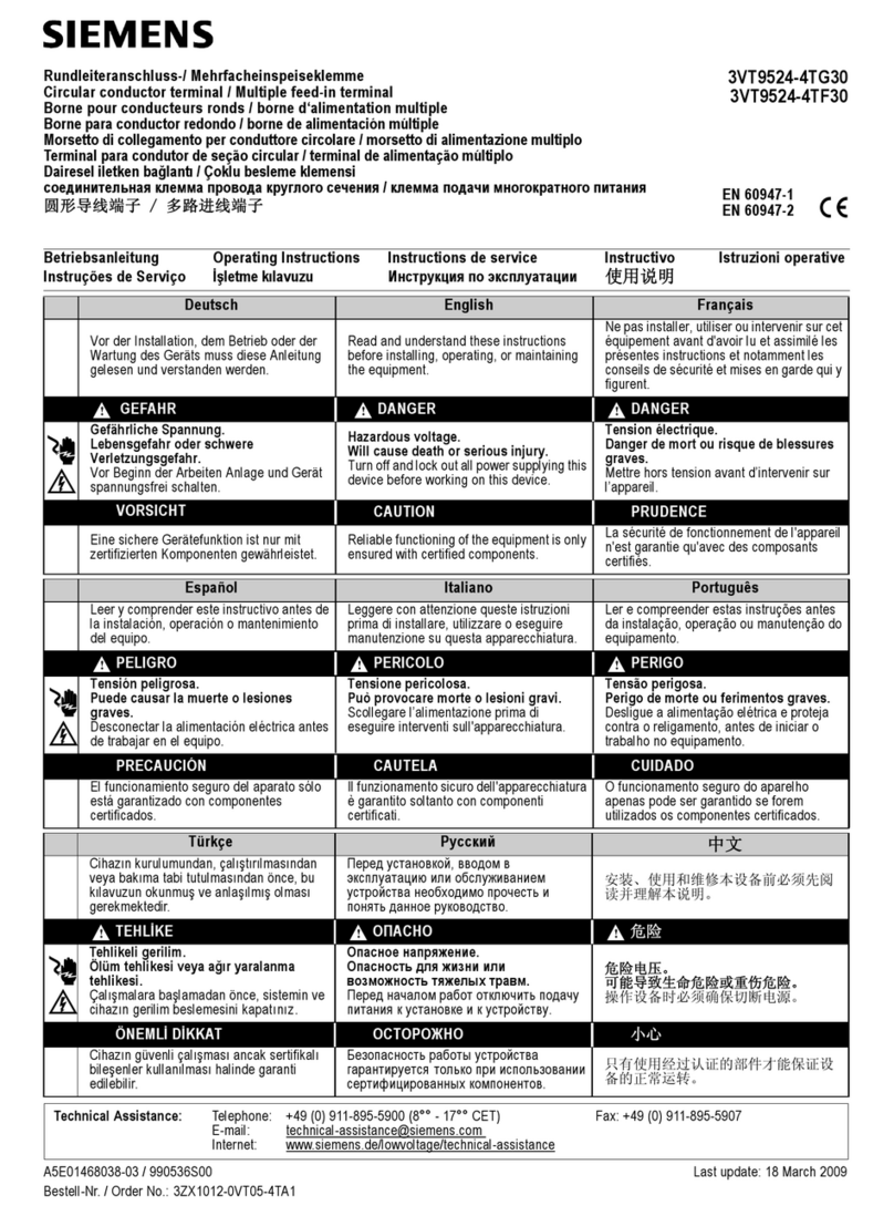
Raycap RSCAC-9556 Series User manual

Installation Instructions:
RSCAC-9556-P-240-A
RSCAC-9556-PS-240-A
RSCAC-9556-PH-240-A
www.raycap.com
INSTALL INSTRUCTIONS RSCAC-9556 Series
RSCAC-9556-P-240-A RSCAC-9556-PS-240-A RSCAC-9556-PH-240-A


www.raycap.com
©Raycap • All rights reserved
(320-1393) Rev.A
Page 1 of 10
INSTALL INSTRUCTIONS RSCAC-9556 Series
Contents
1 Copyright 2
1.1 Disclaimer 2
1.2 Warnings 2
2 Introduction 3
3 OVP Package Contents 3
3.1 Prerequisites 3
3.2 Required Tools and Supplies 3
4 Mounting the Bracket - Options 4
5 PortDenitions 4
6 WiringConguration 5
7 Closing and Securing Unit 9
8 Optional Lock-Out Feature 9

RSCAC-9556 Series INSTALL INSTRUCTIONS
www.raycap.com
©Ra
(320-1393) R
ycap • A
e
ll r
v.A
ights reserved
Page 2 of 10
1.0 Copyright
©Raycap, Inc. 2019 - All Rights Reserved
1.1 Disclaimer
The information in this document is subject to change without notice and describes only the product
dened in the introduction of this documentation. This documentation is intended for the use of
Raycap customers only for the purposes of the agreement under which the document is submitted,
and no part may be used, reproduced, modied or transmitted in any form or means without the prior
written permission of Raycap. The documentation has been prepared to be used by professional
and properly trained personnel, and the customer assumes full responsibility when using it. Raycap
welcomes customer comments as part of the process of continuous development and improvement
of the documentation.
Raycap has made all reasonable efforts to ensure that the instructions contained in this document
are adequate and free of material errors and omissions. Raycap will, if deemed necessary, explain
issues which may not be covered by this document.
The contents of this document are subject to revision without notice due to continued progress in
methodology, design and manufacturing. Raycap shall have no liability for any error damage of any
kind resulting from the use of this document.
1.2 Warnings
Please read this manual prior to use to become familiar with the product’s numerous features and
operating procedures. To maintain the maximum degree of safety, follow the sequences as outlined.
Before using the product, read all instructions and cautionary markings on the product and on any
equipment connected to the product.
CAUTION – Unless otherwise noted, product usage that is not recommended or sold by the product
manufacturer can result in risk of re, electric shock, or injury to persons.
CAUTION – Do not operate the product if it has been damaged in any way. Return damaged
products to Raycap for repair or replacement.
CAUTION – Do not disassemble the product. Incorrect re-assembling can cause the risk of electrical
shock or re.
WARNING – Disconnect or disable the AC power source to the product prior to beginning its
installation. Ensure that the AC power source to the product remains de-energized until the
completion of the installation and after all connections have been veried to be correctly congured.
For conditions other than those described above, please phone a Raycap Account Representative at
(208) 777-1166, (800) 890-2569 or www.raycap.com
Thank you for choosing quality products from Raycap

www.raycap.com
©Raycap • All rights reserved
(320-1393) Rev.A
Page 3 of 10
INSTALL INSTRUCTIONS RSCAC-9556 Series
2.0 Introduction
In a split Radio Base Station (RBS) architecture the typical RBS consists of a Base Band Unit
(BBU) and Remote Radio Heads (RRH) connected by cabling. Power to the RRH is provided
through copper cables traveling from the base station to the top of the tower or roof top. This
creates a conductive path, making the active equipment at the top and the base of the site
vulnerable to damage by direct lightning strikes. Protection systems installed in front of both
the BBU and the RRH must be able to withstand direct lightning currents in order to protect
the sensitive equipment. Raycap’s RRH solutions featuring Strikesorb® SPD technology
signicantly enhance the reliability & availability of the RRH site by providing superior electrical
protection at the RRH and BBU, and also enable power cable management solutions.
3.0 OVP Package Contents
1 each
Enclosure, Cover and Base, Mounting Feet Hardware
Metal Mounting Bracket
Bracket Hardware Kit
3.1 Prerequisites
This document describes how to install the RSCAC-9556-P/PS/PH-240-A on-site and how to
mount, and connect it to external interfaces.
Installers of Raycap’s RRH surge protective and ber/power management solutions must be
industry professionals who have attended training on the proper installation of the equipment
by Raycap and/or the mobile operator. Installers are required to read this installation guide
thoroughly prior to installation of the Raycap RRH protection equipment.
3.2 Required Tools & Supplies
7/16" Nut driver (mounting bracket)
Wire cutter
Wire strippers
#1 Philips head screwdriver

RSCAC-9556 Series INSTALL INSTRUCTIONS
www.raycap.com
©Ra
(320-1393) R
ycap • A
e
ll r
v.A
ights reserved
Page 4 of 10
Procedure
Mounting the Bracket
4.1 Enclosure mounted on bracket
4.2 Option 1: Pole Mount
4.3 Option 2: Monopole
4.4 Option 3: Unistrut
Metal mounting bracket NOT used
Procedure
PortDenitions
5.1 See picture to identify
Base Port
Assembly Denitions
5.2 Torque Values for Sealing
Cable Glands
AC Cables: 44.2 in-lb (5.0 N-m)
AC (Out)AC (In) Ground
Banding Locations

www.raycap.com
©Raycap • All rights reserved
(320-1393) Rev.A
Page 5 of 10
INSTALL INSTRUCTIONS RSCAC-9556 Series
Procedure
WiringConguration
6.1 Loosen the 4 thumbscrews on outside cover
or unclasp latch to open cover.
6.2 Flip all breakers to “OFF” position to ensure
there is no power to circuits.
6.3 Remove (4) Philips head screws and set the
screws and dead-front aside.

RSCAC-9556 Series INSTALL INSTRUCTIONS
www.raycap.com
©Ra
(320-1393) R
ycap • A
e
ll r
v.A
ights reserved
Page 6 of 10
6.3 NOTE: Suitable for Use Service Entrance (SUSE).
6.4 Install Ground Cable as shown.
RSCAC-9556-PS-240-A (Shunt Trip version shown with breakers installed)

www.raycap.com
©Raycap • All rights reserved
(320-1393) Rev.A
Page 7 of 10
INSTALL INSTRUCTIONS RSCAC-9556 Series
6.5 Install AC Power “IN” as shown.
Note: Ground Cable not shown for clarity.

RSCAC-9556 Series INSTALL INSTRUCTIONS
www.raycap.com
©Ra
(320-1393) R
ycap • A
e
ll r
v.A
ights reserved
Page 8 of 10
6.6 Install AC Power “OUT” as shown.
Note: Ground Cable and AC Power IN Cables not shown for clarity.
One of available twelve circuits installed.
AC (Out) AC (Out) AC (In) Ground

www.raycap.com
©Raycap • All rights reserved
(320-1393) Rev.A
Page 9 of 10
INSTALL INSTRUCTIONS RSCAC-9556 Series
6.7 Ground cable, AC Power (IN) and AC Power (OUT) (1 circuit) installed.
6.8 Replace dead-front, ip breaker “ON” to power circuits.
Procedure
Closing and securing unit
7.1 Close cover. Secure cover clip.
7.2 Installation Complete
Optional Lock-Out Feature
8.1 With cover clip engaged, secure with lock
(not provided).
Clip not included with RSCAC-9556-PH-240-A.

www.raycap.com
©Raycap • All rights reserved
(320-1393) Rev.A
RSCAC-9556 Series INSTALL INSTRUCTIONS
This manual suits for next models
3
Table of contents
Other Raycap Circuit Breaker manuals