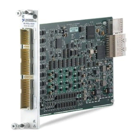
NI PXIe-1486 User manual

GETTING STARTED GUIDE
PXIe-1486
FlexRIO FPD-Link Interface Module
This document explains how to install and configure the following variants of the PXIe-1486:
• PXIe-1486 FlexRIO FPD-Link™ Deserializer
• PXIe-1486 FlexRIO FPD-Link™ Serializer
• PXIe-1486 FlexRIO FPD-Link™ SerDes
After completing the tasks described in this document, you will have a hardware and driver
setup that allows you to design and test your software application.
Note If you purchased the PXIe-1486 as part of an NI system, refer to your system
documentation for application-specific instructions for using the PXIe-1486.
Contents
FlexRIO Documentation and Resources...................................................................................2
Preparing the System Components........................................................................................... 3
Unpacking the Kit............................................................................................................. 3
Verifying the Kit Contents................................................................................................ 3
System Components..........................................................................................................3
Prerequisites.............................................................................................................................. 4
Verifying the System Requirements..................................................................................4
Installing the Software.............................................................................................................. 4
Installing the PXIe-1486........................................................................................................... 4
Cabling the PXIe-1486..............................................................................................................4
Configuring the PXIe-1486 in MAX........................................................................................ 8
Accessing FlexRIO with Integrated I/O Examples...................................................................9
Common FlexRIO with Integrated I/O Examples.......................................................... 10
Component-Level Intellectual Property (CLIP)..................................................................... 10
Front Panels, Connectors, and Block Diagrams......................................................................11
PXIe-1486 Deserializer Front Panel, Connectors, and Block Diagram..........................11
PXIe-1486 Serializer Front Panel, Connectors, and Block Diagram..............................14
PXIe-1486 SerDes Front Panel, Connectors, and Block Diagram................................. 17
FPGA Carrier Block Diagram.........................................................................................20
Where to Go Next................................................................................................................... 20
NI Services..............................................................................................................................20

FlexRIO Documentation and Resources
Use the following resources to find more information about the PXIe-1486.
All product documentation can be found at ni.com/manuals or in LabVIEW by clicking Help.
Table 1. FlexRIO Documentation and Resources
Document Contents
PXIe-1486 Getting Started
Guide (this document)
• Installation instructions
• Basic programming instructions
PXIe-1486 Specifications • Operating environment requirements
• IO specifications
• Clocking specifications
• Physical and mechanical specifications
PXIe-1486 Safety,
Environmental, and Regulatory
Information
• Safety and compliance information
• Environmental information
LabVIEW FPGA Module Help • Basic functionality of the FPGA module
• Instructions for developing and debugging custom
hardware logic
NI-FlexRIO Readme • Minimum system requirements
• Supported Application Development Environments
(ADEs)
• Known issues and bug fixes
• Recent updates
FlexRIO Help • Hardware reference information
• Programming instructions
• I/O Component Level IP (CLIP) development
information
LabVIEW Examples • Examples showing how to run FPGA VIs on your
device
• How showing how to run host VIs on your device
FlexRIO product page • Product information
• Data sheets
2| ni.com | PXIe-1486 Getting Started Guide

Preparing the System Components
Unpacking the Kit
Notice To prevent electrostatic discharge (ESD) from damaging the device, ground
yourself using a grounding strap or by holding a grounded object, such as your
computer chassis.
1. Touch the antistatic package to a metal part of the computer chassis.
2. Remove the device from the package and inspect the device for loose components or any
other sign of damage.
Notice Never touch the exposed pins of connectors.
Note Do not install a device if it appears damaged in any way.
3. Unpack any other items and documentation from the kit.
Store the device in the antistatic package when the device is not in use.
Verifying the Kit Contents
Verify that the following items are included in the PXIe-1486 kit.
Figure 1. Kit Contents
1 2 3 4
1. PXIe-1486 Module
2. Terminal blocks
3. PXIe-1486 Safety, Environmental, and Regulatory
Information
4. PXIe-1486 Getting Started Guide (This
Document)
System Components
The PXIe-1486 is intended for use with the following system components.
Required System Components
• PXIe chassis with slot cooling capacity ≥58 W
• Camera or serial device (for Deserializer or SerDes modules)
PXIe-1486 Getting Started Guide | © National Instruments Corporation | 3

• Engine control unit (for Serializer or SerDes modules)
• PXI Express embedded controller or PC with MXI controller system
Optional System Components
• Power source (for Deserializer or SerDes modules)
• Power sink (for Serializer or SerDes modules)
• Copper power connector wire
• FAKRA Female Code Z to FAKRA Female Code Z Cable(s)
Note See the PXIe-1486 Specifications for detailed information on compatible
serial devices, chassis, copper connector wire, and other system components.
Prerequisites
Verifying the System Requirements
To use the FlexRIO instrument driver, your system must meet certain requirements.
Refer to the product readme, which is available online on the driver software download page
or at ni.com/manuals, for more information about minimum system requirements,
recommended system, and supported application development environments (ADEs).
Installing the Software
Download the following software from ni.com/downloads.
Note NI software includes NI Package Manager to handle the installation. Refer to
the NI Package Manager Manual at ni.com/r/nipmmanual for more information
about installing, removing, and upgrading NI software using NI Package Manager.
• LabVIEW
• LabVIEW FPGA Module
• FlexRIO
Installing the PXIe-1486
For instructions on how to install your PXIe-1486 into the chassis, refer to your chassis
documentation, available at ni.com/manuals.
Cabling the PXIe-1486
Complete the following steps to connect your PXIe-1486 to other system components.
1. Connect your chassis to a power source as described in the chassis Getting Started Guide.
4| ni.com | PXIe-1486 Getting Started Guide

2. Connect serial device(s) and ECU(s) as required for your application.
a) For Deserializer or SerDes modules, use a FAKRA cable to connect serial device(s)
to the PXIe-1486 serial input (SI) connector(s).
b) For Serializer or SerDes modules, use a FAKRA cable to connect ECU(s) to the
PXIe-1486 serial output (SO) connector(s).
Note Serial output and serial input coaxial connectors on the PXIe-1486 are
physically identical. They can be differentiated by their labels. Serial output
channels are labeled SO and serial input connectors are labeled SI.
3. Connect the terminal blocks included in your kit to the AUX power connectors on the
PXIe-1486.
4. (Optional) Connect power sink(s) or power source(s) to the AUX power connectors as
required for your application.
a) For Deserializer or SerDes modules, use a copper conductor wire to connect a power
source to the serial input channel's corresponding pin on the AUX power connector.
This allows you to supply external power. If you do not connect an external power
source, devices connected to PXIe-1486 can be powered by the chassis backplane.
b) For Serializer or SerDes modules, use a copper conductor wire to connect a power
sink to the serial output channel's corresponding pin on the AUX power connector.
This allows you to simulate an additional load.
Note AUX power connector pins map to serial input and serial output
connectors one to one.
Refer to the following diagrams for examples of cabled configurations.
PXIe-1486 Getting Started Guide | © National Instruments Corporation | 5

Figure 2. PXIe-1486 Deserializer
1
6
5
3
4
2
1. PXIe-1486 Deserializer Module
2. Camera or Serial Device
3. Power Source
4. FAKRA Female Code Z to Serial Device
Connector Cable
5. Power Connector Wire, Grounding
6. Power Connector Wire, Positively Charged
6| ni.com | PXIe-1486 Getting Started Guide

Figure 3. PXIe-1486 Serializer
1
6
5
4
2
3
1. PXIe-1486 Serializer Module
2. Engine Control Unit (ECU)
3. Power Sink
4. FAKRA Female Code Z to FAKRA Female Code Z
Cable
5. Power Connector Wire, Grounding
6. Power Connector Wire, Positively Charged
PXIe-1486 Getting Started Guide | © National Instruments Corporation | 7

Figure 4. PXIe-1486 SerDes
1
4
5
3
2
1. PXIe-1486 SerDes Module
2. Engine Control Unit (ECU)
3. FAKRA Female Code Z to FAKRA Female Code Z
Cable
4. Camera or Serial Device
5. Power Connector Wire, Positively Charged
Note In the PXIe-1486 SerDes module configuration shown, the power connector
wire allows the ECU to power the camera or serial device.
Related Information
PXIe-1486 Deserializer Front Panel, Connectors, and Block Diagram on page 11
PXIe-1486 Serializer Front Panel, Connectors, and Block Diagram on page 14
PXIe-1486 SerDes Front Panel, Connectors, and Block Diagram on page 17
Configuring the PXIe-1486 in MAX
Use Measurement & Automation Explorer (MAX) to configure your NI hardware. MAX
informs other programs about which NI hardware products are in the system and how they are
configured. MAX is automatically installed with FlexRIO.
1. Launch MAX.
8| ni.com | PXIe-1486 Getting Started Guide

2. In the configuration tree, expand Devices and Interfaces to see the list of installed NI
hardware.
Installed modules appear under the name of their associated chassis.
3. Expand your Chassis tree item.
MAX lists all modules installed in the chassis. Your default names may vary.
Note If you do not see your module listed, press <F5> to refresh the list of
installed modules. If the module is still not listed, power off the system, ensure
the module is correctly installed, and restart.
4. Record the identifier MAX assigns to the hardware. Use this identifier when
programming the PXIe-1486.
5. Self-test the hardware by selecting the item in the configuration tree and clicking Self-
Test in the MAX toolbar.
The MAX self-test performs a basic verification of hardware resources.
Accessing FlexRIO with Integrated I/O
Examples
The NI-FlexRIO driver includes several example applications for LabVIEW. These examples
serve as interactive tools, programming models, and as building blocks in your own
applications. Complete the following steps to access all FlexRIO with Integrated I/O getting
started examples.
1. In LabVIEW, click Help »Find Examples .
2. In the NI Example Finder window that opens, click Hardware Input and Output »
FlexRIO »Integrated IO »Getting Started .
3. Double click Getting Started with FlexRIO Integrated IO.vi.
The FlexRIO with Integrated IO Project Creator window will open.
4. Select the example that corresponds to the name of your FlexRIO module. The
Description window includes a short description of the getting started example for your
device. Rename the project, select a location for this project, and click OK.
The Project Explorer window for your new project opens.
Online examples are also available to demonstrate FlexRIO basics, such as using DRAM,
acquiring data, and performing high throughput streaming. To access these examples, search
FlexRIO examples in the Search the community field at ni.com/examples.
PXIe-1486 Getting Started Guide | © National Instruments Corporation | 9

Common FlexRIO with Integrated I/O Examples
In addition to the examples within the FlexRIO with Integrated IO Project Creator, NI
provides several examples that apply to all FlexRIO with Integrated I/O modules to help you
perform common tasks.
The following examples can be found in the NI Example Finder:
•Show All FlexRIO with Integrated IO Hardware.vi queries and displays a
set of hardware properties from all FlexRIO with Integrated I/O devices in a chassis.
•Vivado Export Getting Started Ultrascale.lvproj demonstrates the use
of the Vivado Project Export feature.
•Read-Write Calibration Data.vi demonstrates how to read and write calibration
data and metadata into the storage space of FlexRIO with Integrated I/O devices.
Component-Level Intellectual Property (CLIP)
The LabVIEW FPGA Module includes component-level intellectual property (CLIP) for HDL
IP integration. FlexRIO devices support two types of CLIP: user-defined and socketed.
•User-defined CLIP allows you to insert HDL IP into an FPGA target, enabling VHDL
code to communicate directly with an FPGA VI.
•Socketed CLIP provides the same IP integration of the user-defined CLIP, but it also
allows the CLIP to communicate directly with circuitry external to the FPGA. Adapter
module socketed CLIP allows your IP to communicate directly with both the FPGA VI
and the external adapter module connector interface.
The PXIe-1486 ships with socketed CLIP items that add module I/O to the LabVIEW project.
10 | ni.com | PXIe-1486 Getting Started Guide

Front Panels, Connectors, and Block Diagrams
PXIe-1486 Deserializer Front Panel, Connectors, and
Block Diagram
Figure 5. PXIe-1486 Deserializer Front Panel
PXIe-1486
FlexRIO FPD-LINK
TM III Deserializer
AUX POWER
SI 0
SI 2
SI 3
SI 1
SI 4
SI 6
SI 7
SI 5
0
1
2
3
4
5
9-30 V
800 mA MAX
6
7
Table 2. PXIe-1486 Deserializer Front Panel Connectors Signal Descriptions
Signal Name Description FlexRIO Terminal Name
SI 0 Serial input to internal deserializer SI0
SI 1 Serial input to internal deserializer SI1
SI 2 Serial input to internal deserializer SI2
SI 3 Serial input to internal deserializer SI3
PXIe-1486 Getting Started Guide | © National Instruments Corporation | 11

Table 2. PXIe-1486 Deserializer Front Panel Connectors Signal
Descriptions (Continued)
Signal Name Description FlexRIO Terminal Name
SI 4 Serial input to internal deserializer SI4
SI 5 Serial input to internal deserializer SI5
SI 6 Serial input to internal deserializer SI6
SI 7 Serial input to internal deserializer SI7
Figure 6. PXIe-1486 Deserializer AUX Power Connectors
0
1
2
3
4
5
6
7
1
2
3
4
5
6
7
8
9
10
11
12
Table 3. PXIe-1486 Deserializer AUX Power Connectors Signal Descriptions
Signal Pin Description
1 Power supply for channel SI 0
2 Power supply for channel SI 1
3 Digital/chassis grounding
4 Digital/chassis grounding
5 Power supply for channel SI 2
6 Power supply for channel SI 3
7 Power supply for channel SI 4
8 Power supply for channel SI 5
9 Digital/chassis grounding
10 Digital/chassis grounding
12 | ni.com | PXIe-1486 Getting Started Guide

Table 3. PXIe-1486 Deserializer AUX Power Connectors Signal
Descriptions (Continued)
Signal Pin Description
11 Power supply for channel SI 6
12 Power supply for channel SI 7
Figure 7. PXIe-1486 Deserializer I/O Block Diagram
SI0 Des0
DS90UB954
PoC
Select
SI 0 CSI-2 Data
SI 0 Deserializer GPIO
SI 0 Deserializer I2C / Des0_I2C
Des0_RefClk
Des1_RefClk
Des2_RefClk
Des3_RefClk
Des1
DS90UB954
Des2
DS90UB954
Des3
DS90UB954
SI1
SI2
SI3
SI 1 CSI-2 Data
SI 1 Deserializer GPIO
SI 1 Deserializer I2C / Des1_I2C
Internal (12 V)
Aux Power
None
PoC
Select
Internal (12 V)
Aux Power
None
PoC
Select
Internal (12 V)
Aux Power
None
PoC
Select
Aux
Power
PLL
Internal (12 V)
Aux Power
Aux Power
None
SI 2 CSI-2 Data
SI 2 Deserializer GPIO
SI 2 Deserializer I2C / Des2_I2C
SI 3 CSI-2 Data
SI 3 Deserializer GPIO
SI 3 Deserializer I2C / Des3_I2C
SI4 Des4
DS90UB954
PoC
Select
SI 4 CSI-2 Data
SI 4 Deserializer GPIO
SI 4 Deserializer I2C / Des4_I2C
Des4_RefClk
Des5_RefClk
Des6_RefClk
Des7_RefClk
Des5
DS90UB954
Des6
DS90UB954
Des7
DS90UB954
SI5
SI6
SI7
SI 5 CSI-2 Data
SI 5 Deserializer GPIO
SI 5 Deserializer I2C / Des5_I2C
Internal (12 V)
Aux Power
None
PoC
Select
Internal (12 V)
Aux Power
None
PoC
Select
Internal (12 V)
Aux Power
None
PoC
Select
Aux
Power
PLL
I/O
Mezzanine
Connector
Internal (12 V)
Aux Power
Aux Power
None
SI 6 CSI-2 Data
SI 6 Deserializer GPIO
SI 6 Deserializer I2C / Des6_I2C
SI 7 CSI-2 Data
SI 7 Deserializer GPIO
SI 7 Deserializer I2C / Des7_I2C
PXIe-1486 Getting Started Guide | © National Instruments Corporation | 13

PXIe-1486 Serializer Front Panel, Connectors, and
Block Diagram
Figure 8. PXIe-1486 Serializer Front Panel
PXIe-1486
FlexRIO FPD-LINK
TM III Serializer
SO 0
SO 2
SO 3
SO 1
SO 4
SO 6
SO 7
SO 5
0
1
2
3
4
5
9-30 V
800 mA MAX
6
7
AUX POWER
Table 4. PXIe-1486 Serializer Front Panel Connectors Signal Descriptions
Signal Name Description FlexRIO Terminal Name
SO 0 Serial output from internal serializer SO0
SO 1 Serial output from internal serializer SO1
SO 2 Serial output from internal serializer SO2
SO 3 Serial output from internal serializer SO3
SO 4 Serial output from internal serializer SO4
SO 5 Serial output from internal serializer SO5
14 | ni.com | PXIe-1486 Getting Started Guide

Table 4. PXIe-1486 Serializer Front Panel Connectors Signal Descriptions (Continued)
Signal Name Description FlexRIO Terminal Name
SO 6 Serial output from internal serializer SO6
SO 7 Serial output from internal serializer SO7
Figure 9. PXIe-1486 Serializer AUX Power Connectors
0
1
2
3
4
5
6
7
1
2
3
4
5
6
7
8
9
10
11
12
Table 5. PXIe-1486 Serializer AUX Power Connectors Signal Descriptions
Signal Pin Description
1 Power sink for channel SO 0
2 Power sink for channel SO 1
3 Digital/chassis grounding
4 Digital/chassis grounding
5 Power sink for channel SO 2
6 Power sink for channel SO 3
7 Power sink for channel SO 4
8 Power sink for channel SO 5
9 Digital/chassis grounding
10 Digital/chassis grounding
11 Power sink for channel SO 6
12 Power sink for channel SO 7
PXIe-1486 Getting Started Guide | © National Instruments Corporation | 15

Figure 10. PXIe-1486 Serializer I/O Block Diagram
SO4 Ser4
DS90UB953
PoC
Select
SO 4 CSI-2 Data
SO 4 Serializer GPIO
SO 4 Serializer I2C / Ser4_I2C
Ser4_RefClk
Ser5_RefClk
Ser6_RefClk
Ser7_RefClk
Ser5
DS90UB953
Ser6
DS90UB953
Ser7
DS90UB953
SO5
SO6
SO7
SO 5 CSI-2 Data
SO 5 Serializer GPIO
SO 5 Serializer I2C / Ser5_I2C
Aux Power
None
PoC
Select
Aux Power
None
PoC
Select
Aux Power
None
PoC
Select
Aux
Power
PLL
Aux Power
Aux Power
None
SO 6 CSI-2 Data
SO 6 Serializer GPIO
SO6 Serializer I2C / Ser6_I2C
SO 7 CSI-2 Data
SO 7 Serializer GPIO
SO 7 Serializer I2C / Ser7_I2C
SO0 Ser0
DS90UB953
PoC
Select
SO 0 CSI-2 Data
SO 0 Serializer GPIO
SO 0 Serializer I2C / Ser0_I2C
Ser0_RefClk
Ser1_RefClk
Ser2_RefClk
Ser3_RefClk
Ser1
DS90UB953
Ser2
DS90UB953
Ser3
DS90UB953
SO1
SO2
SO3
SO 1 CSI-2 Data
SO 1 Serializer GPIO
SO 1 Serializer I2C / Ser1_I2C
Aux Power
None
PoC
Select
Aux Power
None
PoC
Select
Aux Power
None
PoC
Select
Aux
Power
PLL
Aux Power
Aux Power
None
SO 2 CSI-2 Data
SO 2 Serializer GPIO
SO 2 Serializer I2C / Ser2_I2C
SO 3 CSI-2 Data
SO 3 Serializer GPIO
SO 3 Serializer I2C / Ser3_I2C
I/O
Mezzanine
Connector
16 | ni.com | PXIe-1486 Getting Started Guide

PXIe-1486 SerDes Front Panel, Connectors, and Block
Diagram
Figure 11. PXIe-1486 SerDes Front Panel
PXIe-1486
FlexRIO FPD-LINK
TM III SerDes
SO 0
SO 1
SI 1
SI 0
SO 2
SO 3
SI 3
SI 2
0SO
SI
SO
SI
0
1
1
2
2
9-30 V
800 mA MAX
3
3
AUX POWER
Table 6. PXIe-1486 SerDes Front Panel Connectors Signal Descriptions
Signal Name Description FlexRIO Terminal Name
SO 0 Serial output from internal serializer SO0
SI 0 Serial input to internal deserializer SI0
SO 1 Serial output from internal serializer SO1
SI 1 Serial input to internal deserializer SI1
SO 2 Serial output from internal serializer SO2
SI 2 Serial input to internal deserializer SI2
PXIe-1486 Getting Started Guide | © National Instruments Corporation | 17

Table 6. PXIe-1486 SerDes Front Panel Connectors Signal Descriptions (Continued)
Signal Name Description FlexRIO Terminal Name
SO 3 Serial output from internal serializer SO3
SI 3 Serial input to internal deserializer SI3
Figure 12. PXIe-1486 SerDes AUX Power Connectors
0SO
SI
SO
SI
0
1
1
2
2
3
3
1
2
3
4
5
6
7
8
9
10
11
12
Table 7. PXIe-1486 SerDes AUX Power Connectors Signal Descriptions
Signal Pin Description
1 Power sink for channel SO 0
2 Power supply for channel SI 0
3 Digital/chassis grounding
4 Digital/chassis grounding
5 Power sink for channel SO 1
6 Power supply for channel SI 1
7 Power sink for channel SO 2
8 Power supply for channel SI 2
9 Digital/chassis grounding
10 Digital/chassis grounding
11 Power sink for channel SO 3
12 Power supply for channel SI 3
18 | ni.com | PXIe-1486 Getting Started Guide

Figure 13. PXIe-1486 SerDes I/O Block Diagram
SO0 Ser0
DS90UB953
PoC
Select
SO 0 CSI-2 Data
SO 0 Serializer GPIO
SO 0 Serializer I2C / Ser0_I2C
Ser0_RefClk
Des0_RefClk
Ser1_RefClk
Des1_RefClk
Des0
DS90UB954
Ser1
DS90UB953
Des1
DS90UB954
SI0
SO1
SI1
SI 0 CSI-2 Data
SI 0 Deserializer GPIO
SI 0 Deserializer I2C / Des0_I2C
Aux Power
None
PoC
Select
PoC
Select
Aux Power
None
PoC
Select
Aux
Power
PLL
Aux Power
SO 1 CSI-2 Data
SO 1 Serializer GPIO
SO 1 Serializer I2C / Ser1_I2C
SI 1 CSI-2 Data
SI 1 Deserializer GPIO
SI 1 Deserializer I2C / Des1_I2C
SO2 Ser2
DS90UB953
PoC
Select
SO 2 CSI-2 Data
SO 2 Serializer GPIO
SO 2 Serializer I2C / Ser2_I2C
Ser2_RefClk
Des2_RefClk
Ser3_RefClk
Des3_RefClk
Des2
DS90UB954
Ser3
DS90UB953
Des3
DS90UB954
SI2
SO3
SI3
SI 2 CSI-2 Data
SI 2 Deserializer GPIO
SI 2 Deserializer I2C / Des2_I2C
Aux Power
None
PoC
Select
PoC
Select
Aux Power
None
PoC
Select
Aux
Power
PLL
Aux Power
SO 3 CSI-2 Data
SO 3 Serializer GPIO
SO 3 Serializer I2C / Ser3_I2C
SI 3 CSI-2 Data
SI 3 Deserializer GPIO
SI 3 Deserializer I2C / Des3_I2C
Internal (12 V)
Aux Power
None
Internal (12 V)
Aux Power
None
Internal (12 V)
Aux Power
None
Internal (12 V)
Aux Power
None
I/O
Mezzanine
Connector
PXIe-1486 Getting Started Guide | © National Instruments Corporation | 19

FPGA Carrier Block Diagram
Figure 14. PXIe-1486 FPGA Block Diagram
Single Ended GPIO
Power Supplies
PXI Triggers
PXIe_CLK100
PXI_CLK10
Gen3 x8 PCIe
+12 V, +3.3 V
+12 V
+1.8 V
DStarB, DStarC
Differential GPIO
Module Clocking
Synchronization
Reference
Clock
Flash
DRAM†
Bank 0
DRAM†
Bank 1
FPGA
PXIe Backplane
I/O Mezzanine Connector
Where to Go Next
Before you can use your system, you need to configure the connection between the serial
device and the PXIe-1486, build your application, then test and troubleshoot your application.
Contact NI for more information about developing the software resources to operate your
system. See FlexRIO Documentation and Resources for additional information.
NI Services
Visit ni.com/support to find support resources including documentation, downloads, and
troubleshooting and application development self-help such as tutorials and examples.
Visit ni.com/services to learn about NI service offerings such as calibration options, repair, and
replacement.
20 | ni.com | PXIe-1486 Getting Started Guide
Table of contents
Other NI Control Unit manuals
Popular Control Unit manuals by other brands

Pickering
Pickering PXI BRIC 40-563A user manual

Goetze
Goetze 4000 Assembly instructions

CyberResearch
CyberResearch IPDIO 7000 Series quick start guide

GMV
GMV DLV-A3 manual

AlfaRadio
AlfaRadio AlfaSpid Rotator and Controller instruction manual

Honeywell
Honeywell HON 530-E-WG OPERATING AND MAINTENANCE INSTRUCTIONS/ SPARE PARTS