Raycus RFL-P500H User manual

RFL-P500H Pulsed Fiber
LaserUser Guide
Wuhan Raycus Fiber Laser Technologies Co., Ltd.

Wuhan Raycus Fiber Laser Technologies Co., Ltd.
Users Guide RFL-P500H
TABLE OF CONTENTS
1 Safety Information .....................................................................................................................1
1.1 Security Warning...............................................................................................................1
1.2 Laser Safety Grade............................................................................................................1
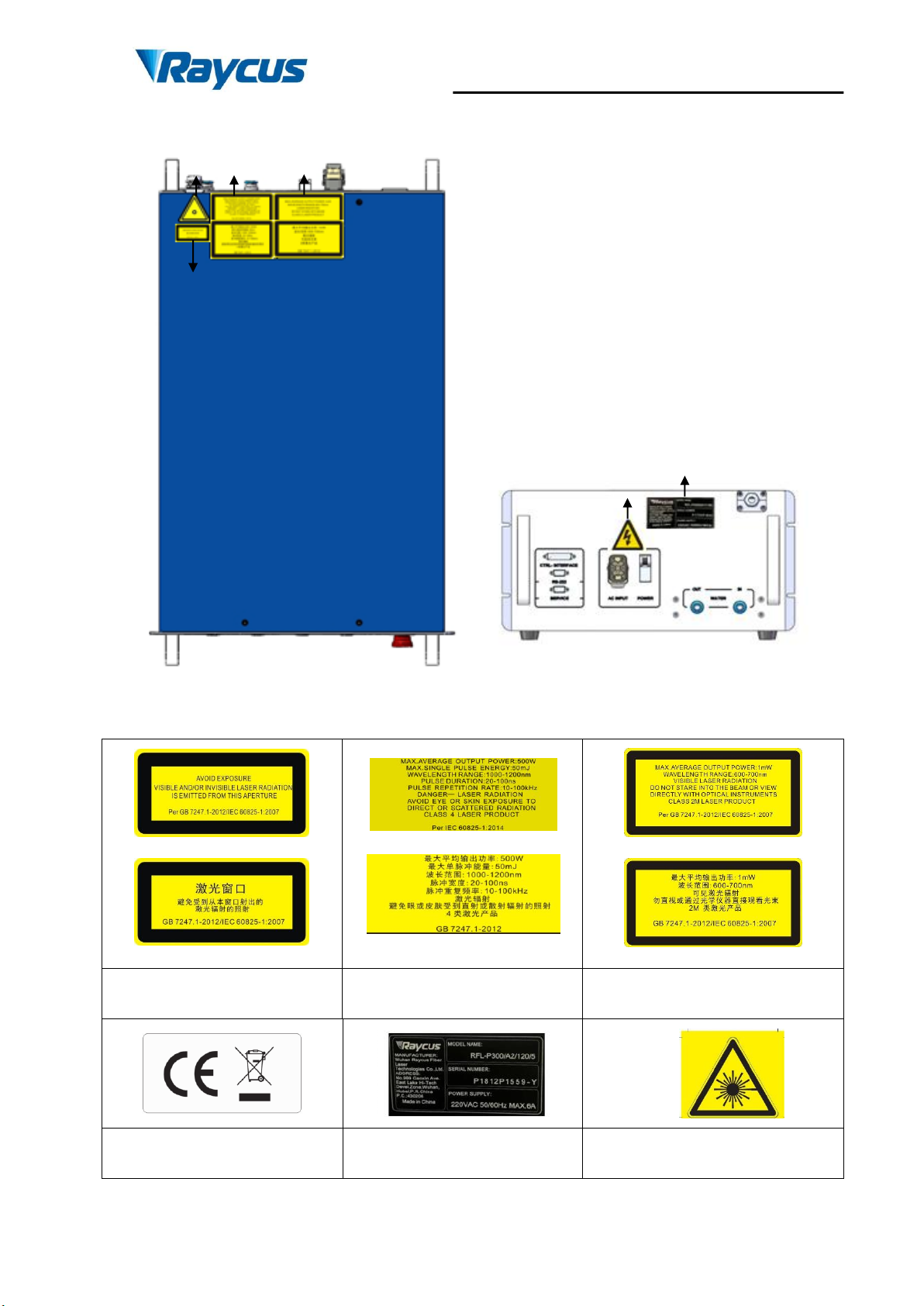
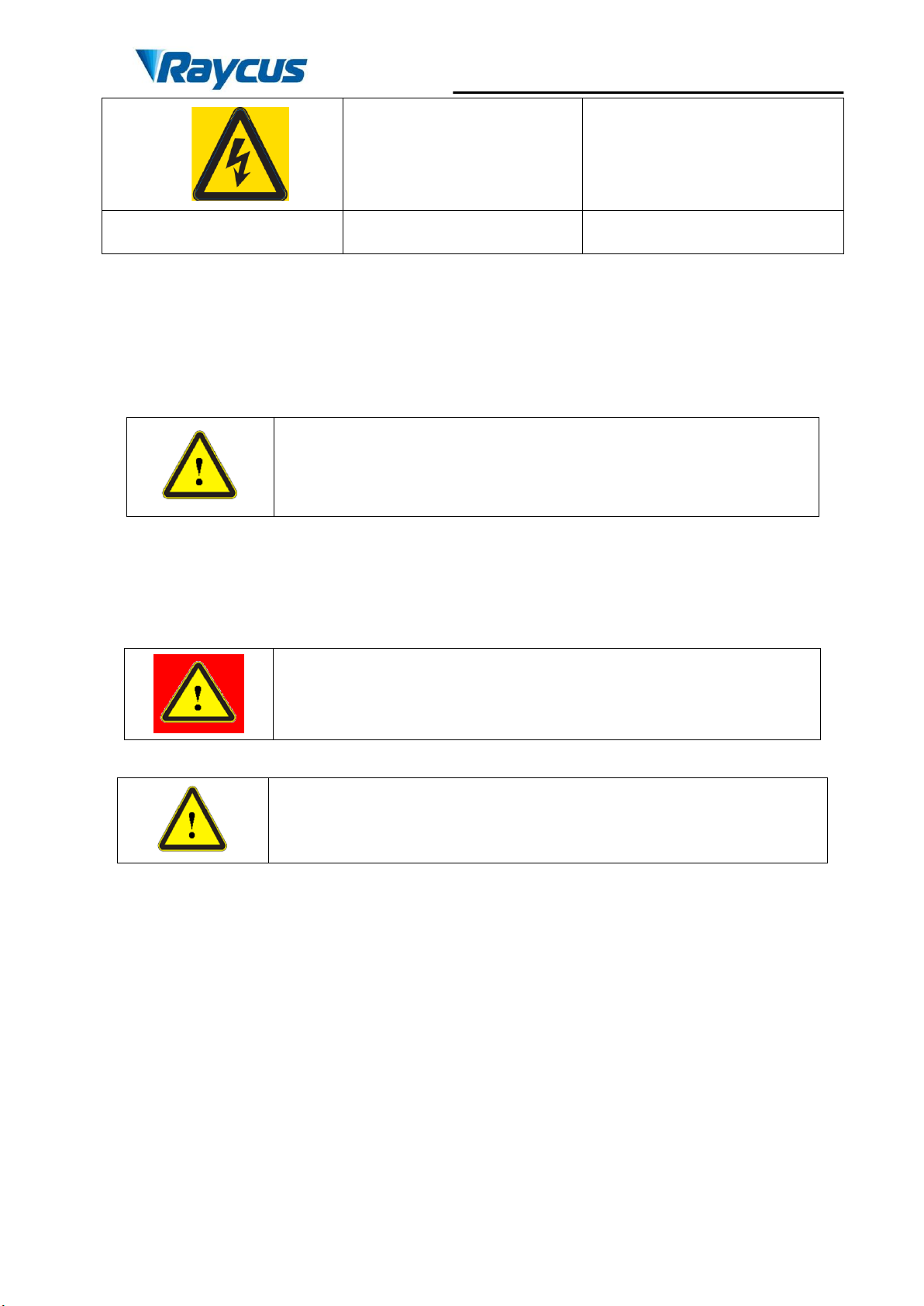
1.3 Safety Identification..........................................................................................................2
1.4 Optical Safety....................................................................................................................3
1.5 Electrical Safety ................................................................................................................3
1.6 Other Safety Rules ............................................................................................................3
2 Product Description ...................................................................................................................4
2.1 Features .............................................................................................................................4
2.2 Package Parts.....................................................................................................................4
2.3 Unpacking and Inspection.................................................................................................4
2.4 Operation Environment.....................................................................................................5
2.5 Attentions..........................................................................................................................6
2.6 Specifications ....................................................................................................................6
3 Installation ..................................................................................................................................8
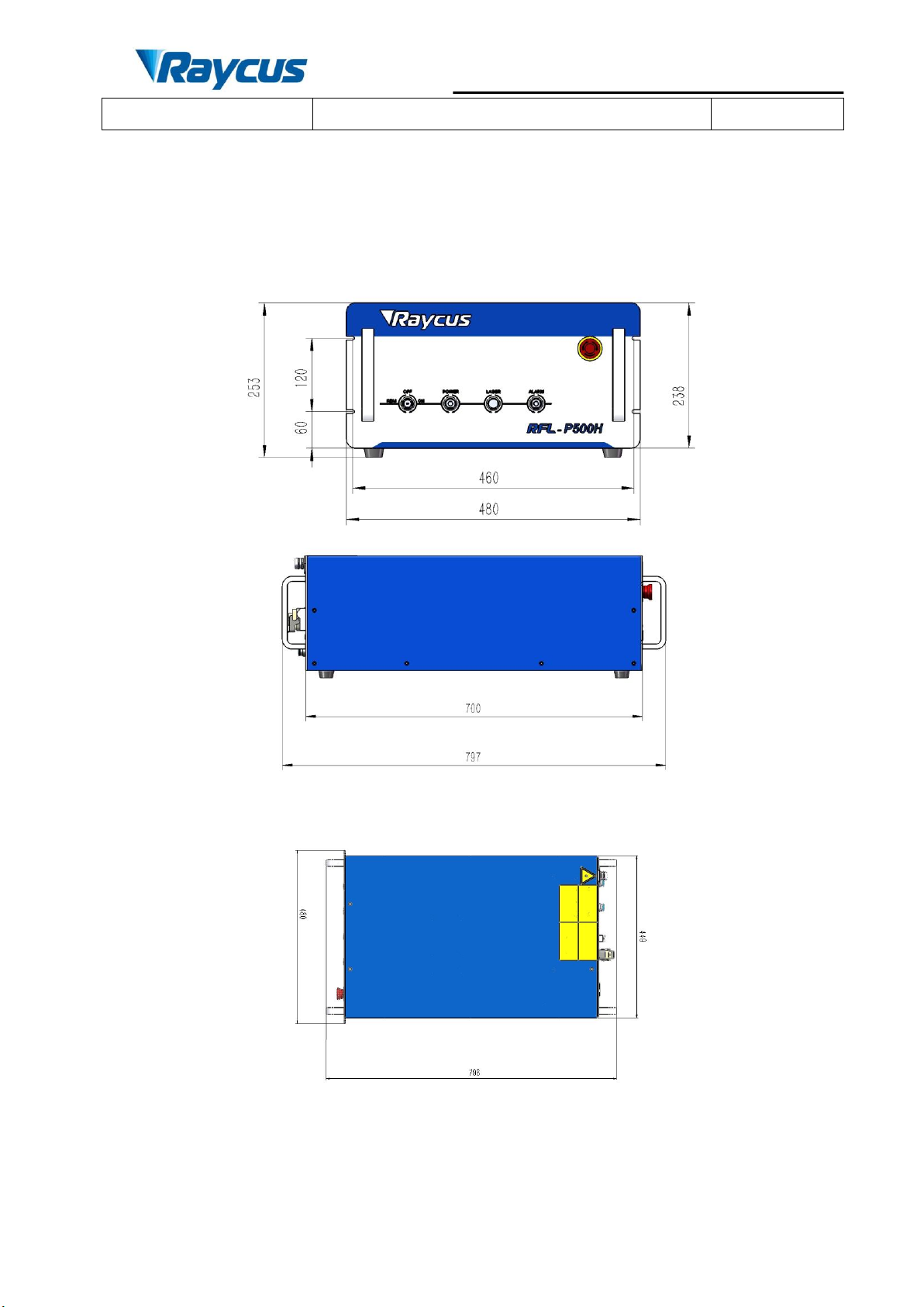
3.1 Dimensions........................................................................................................................8
3.2 Cooling Requirements.......................................................................................................9
3.3 Installation rule................................................................................................................10
4 Using the Product.....................................................................................................................12
4.1 Front Panel ......................................................................................................................12
4.2 Rear Panel .......................................................................................................................13
4.3 Power Connection...........................................................................................................14
4.4 Interface Definitions........................................................................................................15
4.4.1 SERVICE.....................................................................................................................15
4.4.2 Control Interface ..........................................................................................................15
4.4.3 RS-232 Serial Port........................................................................................................21
4.5 Application Steps of Laser Device..................................................................................22
4.5.1 Pre-inspection...............................................................................................................22
4.5.2 Operational Steps .........................................................................................................23
4.5.3 Attention in the process of operation ...........................................................................23
5 Common Alarms and solutions...............................................................................................23
6 Warranty, Return and Maintenance......................................................................................24
6.1 General Warranty............................................................................................................24
6.2 Limitations of Warranty..................................................................................................25
6.3 Service and Repair ..........................................................................................................25

Wuhan Raycus Fiber Laser Technologies Co., Ltd.
User Guide of RFL-P500H
1
1Safety Information
Thank you for choosing Raycus fiber laser. This User Guide provides
important safety, operation, warranty and other information. Please read it
carefully before use this product. In order to ensure safe operation and optimal
performance of the product, please follow the warnings, cautions, operating
procedures and other instructions accordingly.
1.1 Security Warning
WARNING: Describes a hazard that lead to a personal injury
or death.
CAUTION: Describes a hazard that lead to a minor personal
injury or product damage.
1.2 Laser Safety Grade
According to the European Community standards EN 60825-1, clause 9, this
series of lasers are classified as a high power Class 4. This product emits invisible
laser radiation at wavelength of 1064 nm, and the maximum power is 300W.
Direct or indirect exposure of high power of laser radiation may cause damage to
the eyes or skin. Despite the radiation being invisible, the beam may cause
irreversible damage to the retina and cornea. Appropriate and approved laser
goggles must be worn all the time during the laser device is opearting
WARNING: Users must use appropriate laser goggles when
operating this device. The laser goggles is selected according
to the range of wavelength emitted from this product. Users
must ensure that the pretect range of laser goggles over the
entire range of laser wavelengths. Please do not directly view
the laser output head when laser emitting.

Wuhan Raycus Fiber Laser Technologies Co., Ltd.
User Guide of RFL-P500H
2
1.3 Safety Identification
Figure 1 Safety identification position
English Label
Chinese Lable
English Label(300W)
Chinese Lable(300W)
English Label
Chinese Lable
1: Laser Emit Head
2: Type 4 Laser Product
3: Class 2M Laser Product
Label-2mW Red Laser
4: CE
Authentication
5: ID Label
6: Laser Radiation
Hazard
2
6
1
3
5
4

Wuhan Raycus Fiber Laser Technologies Co., Ltd.
User Guide of RFL-P500H
3
7: Electrical Hazard
1.4 Optical Safety
Any dust on the end of the collimator assembly can burn the lens and damage
the laser device.
CAUTION: DO NOT emit when the protective cap is not
removed, otherwise the lens or crystal will be damaged.
1.5 Electrical Safety
a) Ensure the product is grounded through the PE line of the AC power cord.
The grounding must be firm and reliable.
WARNING: Any interruption from the protective earth will
electrify the enclosure, which may result in personal injury.
b) Ensure that the AC voltage is supplied normally.
CAUTION:Wrong wiring mode or power supply voltage will
cause an un recoverable damage to the laser device.
1.6 Other Safety Rules
a) Do not directly view the laser output head when laser emitting. Avoid using
the laser in a dark environment.
b) Do not use fiber lasers in dark environments.
c) If this device is used in a manner not specified in this document, the
protection provided by the device may be impaired and the warranty will be
voided.

Wuhan Raycus Fiber Laser Technologies Co., Ltd.
User Guide of RFL-P500H
4
d) There are no user serviceable parts, equipment or assemblies inside the
product. All service and maintenance shall be performed by Raycus. In
order to prevent electric shock, please do not break the seal or uncover the
shield. Failure to comply with this instruction will void the warranty.
2Product Description
2.1 Features
Raycus pulse fiber laser is designed for industrial and scientific research
applications with high pump conversion efficiency, low power consumption and
excellent beam quality. It is compact and ready to use. It can be used as a
stand-alone unit or easily inserted into user’s apparatus.
Main Features:
Uniform distribution of stop energy
Fiber output
High reliability, long-life
Maintenance free operation
High wall-plug efficiency
Applications:
Laser cleaning
Scientific research
2.2 Package Parts
Please refer to package accessoriesare in the packing box.
2.3 Unpacking and Inspection
Raycus fiber laser is delivered in a package, which is designed to offer the
maximal safety. Upon the delivery, please inspect all packaging for evidence of
mishandling or damage. If you find any evidence of mishandling, please keep the
damaged material and contact the shipping agent and Raycus immediately.

Wuhan Raycus Fiber Laser Technologies Co., Ltd.
User Guide of RFL-P500H
5
Please double check if each listed contents is inside the package; and contact
Raycus as soon as possible if there is any issue.
Take extra care when removing the unit from the package to make the fiber
optic cable stay away from collision and vibration. Please do NOT distort,bend or
pull the output cable when unpacking the device; and avoid any collision to the
head of laser output.
CAUTION: The fiber optic cable and output head are precise
optic instrument, ANY vibration or impact to the output head, and
twist or excessive bend to the cable will damage the instrument.
2.4 Operation Environment
The operation conditions are listed as the following table:
Table 1 The Operation Environment Conditions for the Laser
Power Supply
AC 220V±10%、50/60Hz
Max. Power
Consumption(W)
2500W
Installation
Environment
Flat and no vibration
Ambient
Temperature
10℃~40℃
Relative Humidity
≤70%
Weight(kg)
56kg
a) Make sure the product is properly grounded before use.
b) The laser output head is connected with fiber optic cable. Please inspect the
output head carefully for dust or other contaminations. Use appropriate lens
paper to clean it if necessary.
c) Failure to follow the instructions when operatingthelaser may cause
malfunction and damage.
d) It is not allowed to install the output head when the laser is in operation.

Wuhan Raycus Fiber Laser Technologies Co., Ltd.
User Guide of RFL-P500H
6
e) Do not look into the output head directly. Wear appropriate protective eye
glasses all the time when operating the laser.
It is recommended to install the product in an environment with air
conditioning.
2.5 Attentions
a) Make sure that the correct voltage of 220VAC is used. Failure to connectly
connect power supply will damage the device.
b) The output laser is collimated by the collimating lens, it is important to
keep the collimating lens clean, otherwise it will damage the device.
c) Please cap the output head when it is not in use. Do not touch the output
lens at any time.Use appropriate lens paper to clean it if necessary.
d) Safety keep the cap when using the laser. To avoid dust, make sure the
opening direction of the cap is put down.
e) Failure to follow the instructions may cause laser power loss, such loss is
not covered by warranty.
2.6 Specifications
Table 2 Product Specifications
Items
Test Condition
Value
Unit
Optical Characteristics
Operation Mode
Pulse
/
Polarization State
Random
/
Output Power
RR=10kHz@100ns Pmax
500≤P≤520
W
RR=13kHz@70ns Pmax
500≤P≤520
W
RR=15kHz@50ns Pmax
500≤P≤520
W
RR=25kHz@30ns Pmax
500≤P≤520
W
RR=45kHz@20ns Pmax
500≤P≤520
W
Output Power
Tunability
/
10-100
%
Emission Wavelength
RR=25kHz@30ns Pmax
1064±5
nm

Wuhan Raycus Fiber Laser Technologies Co., Ltd.
User Guide of RFL-P500H
7
Spectral Width
RR=25kHz@30ns Pmax
≤10
nm
Output Power
Unstability
5Hrs 后/RR=50kHz
P=Pmax
≤5
%
Pulse length
RR=10kHz@100ns Pmax
90-100
ns
RR=13kHz@70ns Pmax
65-75
ns
RR=15kHz@50ns Pmax
45-55
ns
RR=25kHz@30ns Pmax
27-33
ns
RR=45kHz@20ns Pmax
17-23
ns
Pulse turn-off time
RR=50kHz P=100%~
10%Pmax
<300
us
Repetition frequency
/
10-100
kHz
Red Guide Laser
Power
/
0.1~1
mW
Optical Output Characteristics of IQB head
BPP
/
<25
mm*mrad
Fiber core size
/
400
μm
Core Fiber
/
round
/
Delivery Cable
Length*
IQB
15
m
Electrical Characteristics
Power Supply
AC 220V±10%、50/60Hz
V
Max. Power
Consumption
RR=50kHz P=100%~
10%Pmax
2500
W
Control Mode
DB25
/
Other Characteristics
Dimensions(W×H×D)
798×480×253
mm
Weight(kg)
56
kg
Operating Ambient
Temperature (℃)
10~40
℃
Humidity(%)
≤70
%
Storage
Temperature(℃)
-20~60
℃

Wuhan Raycus Fiber Laser Technologies Co., Ltd.
User Guide of RFL-P500H
8
Cooling Method
Water Cooling
/
3Installation
3.1 Dimensions
Figure 2 shows dimensions of the product.
Figure 2 Dimensions of 500W Product (unit:mm)

Wuhan Raycus Fiber Laser Technologies Co., Ltd.
User Guide of RFL-P500H
9
The output head is IQB, the following figure 3 show the details of the IQB output
head.
Figure 3 IQB Output head (unit: mm)
CAUTION:
(1) Keep the protective cap properly, prevent it from
contamination; Or the aperture will be contaminated when
capped.
(2) Make sure the aperture and the cavity of the processing head is
clean.
3.2 Cooling Requirements
Table 3 Cooling Requirements
Parameter
Unit
Value
Cooling Capability
W
≥2000
Minimum Flow
L/min
8
Maximum Pressure
Bar
8
Water-cooling pipe
connector
mm
Pagoda-Typepipe
connector,outside diameter
12mm
Temperaturesettingof cooling water:25±0.5℃
Requirements on Cooling Water:Purified water should be used.
a) In order to prevent the growth of mould that may lead to blockage, adding
alcohol solution to about 10% of the total volume is recommended.

Wuhan Raycus Fiber Laser Technologies Co., Ltd.
User Guide of RFL-P500H
10
b) If ambient temperature is between -10℃and 0℃, we recommend to use
30% alcohol(volume ratio), and replace it every 2 months.
c) If ambient temperature is below -10℃, the chiller with both heating and
cooling functions must be used, and keep it in full-time operation.
Other requirements:
a) Before start the device, ensure that the flow and return connections are
correct connected, and confirm that there is no leakage in all the water
circuits. Any abnormal condition in the water circuits may cause a failure
to the operation of the laser.
b) If the device is not use in a long time, water must be emptied from the
device, and then both the inlet and outlet must be blocked with the caps.
Failure to do so may cause damage to the device.
c) Pleaseuse compressed gas below 0.5MPa when emptyingwaterfromthe
device. Failure to do so may cause permanent equipment damage to cooling
system.
CAUTION: Please set the water temperature according to the
requirements above. Setting the temperature too high may cause
an abnormal performance; and liquid water may be condensed
on the laser module or the output head if a too low temperature
is set, which may cause serious damage to the device.
CAUTION: The cooling system should be turned on first. Check
any water leakage and make sure that the water temperature
reaches the set point before start the laser. (25±0.5℃)
3.3 Installation rule
a) Place the product in an appropriate position, immobilize it if necessary.
b) Check if the power supply has the correct voltage (220VAC±10%,
50/60Hz), and the earth line is connected, make sure it is firm and reliable.

Wuhan Raycus Fiber Laser Technologies Co., Ltd.
User Guide of RFL-P500H
11
c) Connect the power cable and control cable to the product when power
supply is OFF.
d) Clamp the water pipes ontopipe connector, run the chiller to check if there
is any leakage in the water circulation.
e) Check the output head and clean it before installation. This procedure must
be performed by Raycus personnel or person authorized by Raycus.
f) Prevent the delivery cable from treading, pinching or excessive bending
during installation.
g) Make sure the environment is clean, or the output head may be
CAUTION: All the cables can only be connected when power
supply is off. Hot plug may damage the device.
CAUTION:
(1) Ensure that there are no fiber bends in radius less than 30cm
when the product is installed. Avoid excessive twisting and
tight bends during the robotic arm movements.
(2) Tight bends will damage the laser delivery system.
CAUTION:
(3) Keep the protective cap properly, prevent it from
contamination; Or the aperture will be contaminated when
capped.
(4) Make sure the aperture and the cavity of the processing head is
clean.
not be less than 20cm in the non-working state (such as transport and
storage). The minimum bending radius should not be less than 30cm
when the laser is work.
contaminated. It is prohibited to use fan during installation, which will
cause dust in the air.
h) The minimum bending radius of the transmission cable of the laser shall

Wuhan Raycus Fiber Laser Technologies Co., Ltd.
User Guide of RFL-P500H
12
4Using the Product
4.1 Front Panel
Figure 4 shows the front panel.
Figure 4 Front Panel View
1. REM/OFF/ON: Key switch, the power switch of the laser. Insert the key
and then turn the key clockwise to 'ON' to active the laser or turn
anti-clockwise to ‘REM’to active remote control.
2. POWER:Power Indicator, indicates that the power is switched on when
the green LED illumines.
3. LASER: Laser emission button, it’s a button with an red LED
indicator.When this button is pressed down and the LED illumines, the
product is ready to emit laser. Press again will release the button, and
disable the laser emission.
4. ALARM: Alarm indicator, indicates a fault condition when the yellow
LED illumines.
5. EMERGENCY STOP: Press it down to stop the laser immediately. Turn
it clockwise to release, and the product can get back to normal.
1
2
3
4
5

Wuhan Raycus Fiber Laser Technologies Co., Ltd.
User Guide of RFL-P500H
13
4.2 Rear Panel
Figure 5 shows the rear panel:
Figure 5 Rear Panel
1. INPUT: The socket for power supply input that can be only mated with the
plug on the power cord Raycus provided.The socket is provided with a
protective cover and a lock catch. Please use the protective cover and lock
catch when not use the laser device.
2. POWER: Air switch. Controlling the on-off of AC.
3. Control INTERFACE: Control interface. Users can control the laser via
this interface. Please reference table 4.4.2 for specific definition of control
signal. The socket is provided with a protective cover and a lock catch.
Please use the protective cover and lock catch when not use the laser
device.
4. RS-232: RS-232 interface. Users can control the laser by command via
RS-232 communication protocol and get the basic information of the laser.
5. SERVICE:Provide some external functions for customers. See 4.4.1
Interface Specification for details.
6. WATER:The pagoda typepipe connector. The intake and outlet are used
for inflow and reflux cooling water.
3
4
5
2
1
6

Wuhan Raycus Fiber Laser Technologies Co., Ltd.
User Guide of RFL-P500H
14
4.3 Power Connection
CAUTION:
(1) Before connect the product to AC power, you must check up
that the AC supply you will apply is in accordance with the
specifications provided in Table 1.
(2) Failure to correctly connect the cable could damage the
device. Please check whether the power cable and the
control cable is correctly connected before usage.
A power cord is provided in the package, as in Figure 6
Figure 6 The Power Cord of the Laser
One end of the power cord is a plug; insert it into the socket ‘AC INPUT’ on
the rear panel when using the laser. Notice that the plug is wrong-side preventing.
After insert it, lock it with the lever.
The other end of the power cord is stripped off,labeled L, N and PE,
respectively. You should connect the wires to the 220V AC power supply
according to the labels:
–Live Line
- Neutral Line
PE - Ground Wire

Wuhan Raycus Fiber Laser Technologies Co., Ltd.
User Guide of RFL-P500H
15
4.4 Interface Definitions
4.4.1 SERVICE
Figure 7 SERVICE Definitions
The pin definitions are shown in Table 4:
Table 4 SERVICE Definitions
Unit
Definition
Comments
1
Remote key
switch
Equivalent to front panel KEY
SWITCH.
2
6
INTERLOCKA
The pin 6 and 7 needs to be
short-jointed before the laser
is powered on.
7
INTERLOCKB
8
Remote Power ON
Equivalent to front panel
LASER
9
Other pins are unconnected。
SERVICE interface is a DB9 header. If the pins 6 and 7 are disconnected, the
device will immediately interrupt the light, and the Yellow alarm lamp will be lit.
The pin 6 and 7 needs to be short-jointed before the laser is powered on.
Interlock interface must not access active signal,
otherwise it will cause interface damage and laser
failure.
4.4.2 Control Interface
Figure 8 shows a schematic diagram of the DB25 control interface.:

Wuhan Raycus Fiber Laser Technologies Co., Ltd.
User Guide of RFL-P500H
16
Figure 8 DB25 control interface
The DB25 behind the power module is the interface between the control
system (such as marking machine) and the laser system. Be sure to connect reliably
before working. The pins are defined as follows
Table 5 DB25 Control Interface Definition
PIN
Function
Description
1-8(D0-D7)
Power Settings
Data parallel transmission 8bit,D0 is the
lowest level,D7 is the highest level;
Range:0-255
(Hexadecimal system:0X00-0XFF);
0:Minimum power output;
255:Maximum output power
10,13-15,24,25
GND
Digital Grounding Aignal(Digital )
11,12,16,21
Laser alarms
status
See alarm codes in the table 7
17
VCC
+5VDC power supply input.
Providing power for inside isolate chip of
DB25 to ensure that the input and output
signal are valid.
18
Pre-output
optical signal
MO、PA Pre-output optical signal,
High level turn on, low level turn off
19
Output optical
signal
High level turn on, low level turn off
20
Sync
Pulse Repetition Rate (Synchronization) input,
square wave.10KHz-50KHz
22
Guide Laser
signal
High level turn on, low level turn off
23
/
/Reserved PIN.
Unconnected in suspension
a) The pump current of diode laser and the laser output power are controlled
by setting the value of PIN1-PIN8 (TTL level). PIN1-PIN8 can be set from
0~255,corresponding to the laser output power from 0~100%(the

Wuhan Raycus Fiber Laser Technologies Co., Ltd.
User Guide of RFL-P500H
17
actual laser power may not be strictly linear with the setting value). The
relationship between PIN value and output power is shown in Table 6:
Table 6 Definition of power control PIN value
Setting1
Setting 2
Setting 3
Setting 4
PIN 1
0
0
0
0
PIN 2
0
0
0
0
PIN 3
0
0
0
0
PIN 4
0
0
0
0
PIN 5
0
0
0
1
PIN 6
0
0
1
1
PIN 7
0
1
1
1
PIN 8
1
1
1
1
Current
~50 %
~75 %
~87.5 %
~93.75 %
b) Pin 10 and Pin 14are all digital GND.
c) Pin 17 is an external 5V DC voltage to provide power supply for inside
isolate chip of DB25, thus the input and output signals are valid; the input
current is more than 20mA.
d) Pin 18 is the start signal of the MO. Pin19 is the input for the optical output
signal. The electrical level for both Pin18 and Pin19 are 5V. Before turning
on Pin 19, MO signal must be switched ON, in other word, the signal of Pin
18 must be ahead of Pin 19 at least 5 ms, and otherwise the laser machine
may be damaged.
e) Pin 20 provides control of the frequency. The frequency range should be
10kHz~100 kHz, depends on the varying power levels of different laser
machines.
ATTENTION: The frequency signal must be ahead of the EM signal at least
5 ms, otherwise the laser machine may be damaged.
f) Below figure shows DB25 sequence diagram:

Wuhan Raycus Fiber Laser Technologies Co., Ltd.
User Guide of RFL-P500H
18
Figure 9 DB25 sequence diagram
1) TArepresent the initialization time of the laser machine. The initialization
time is less than 10s from power-on to perform initialization.
2) TBrepresent the pump recharge time, usually around 5ms.
3) TCrepresent the frequency switching time. Frequency needs to be
adjusted before optical laser output, and the switching time should not
less than 5ms.
g) Definition of alarm signal:
Table 7 Definition of alarm signal
12PIN
11PIN
16PIN
21PIN
Alarm item
Spare
Low
Low
Low
Temperature alarm
Spare
High
Low
Low
Module Power failure
Spare
Low
Low
High
Normal
Spare
High
Low
High
Spare
Spare
Low
High
Low
Spare
Spare
Low
High
High
System failure
Spare
High
High
Low
Water alarm /
Main power alarm
Spare
High
High
High
Spare
h) Introduction of laser pulse duration control Pin2, 3, 16 and 22 on DB25
port not only used for the foundation control of the laser machine, but also
achieves the pulse duration control as the extender.
Table of contents
Other Raycus Industrial Equipment manuals
Popular Industrial Equipment manuals by other brands

Danfoss
Danfoss VLT FC Series installation guide

Siemens
Siemens LI L Series installation instructions

ABB
ABB HT572696 Operation manual

HMS Networks
HMS Networks Anybus Wireless Bolt IoT AWB1000 user manual

D+H
D+H VCD-0204-0 50-1-ACB-M Series Original instructions, Connection, Dimensions

Sambo
Sambo SBWG Series operating instructions