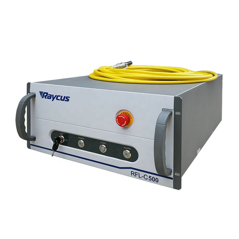
Raycus RFL-C20000XZ User manual

编号
RFL-C20000XZ
•JS02
密级
内1
阶段标记
S
页数
65
名称
RFL-C20000XZ 连续光纤激光器
英文版使用说明书
朱超
单位
连续激光器技术研究部
谢良
编写
阮勇20201218
朱泓旭
校对
刘阳20201218
审核
王建明 20201221
标审
李其军 20201221
批准
王建明 20201224
武汉锐科光纤激光技术股份有限公司
受控
武汉锐科

RFL-C20000XZ
Continuous-Wave
Fiber Laser User
Guide
WuhanRaycusFiberLaserTechnologiesCo.,
Ltd.
受控
武汉锐科

Wuhan Raycus Fiber Laser Technologies Co., Ltd.
User Guide of RFL-C20000XZ
CONTENTS
1. SAFETY INFORMATION................................................................................................................. 1
1.1 SECURITY LABEL ..............................................................................................................................................1
1.2 LASER SAFETY GRADE .......................................................................................................................................2
1.3 OPTICAL SAFETY ..............................................................................................................................................2
1.4 ELECTRICAL SAFETY ..........................................................................................................................................2
1.5 OTHER SAFETY RULES.......................................................................................................................................3
2. PRODUCT DESCRIPTION ............................................................................................................... 3
2.1 FEATURES ......................................................................................................................................................3
2.2 PACKAGE PARTS ..............................................................................................................................................2
2.3 UNPACKING AND INSPECTION.............................................................................................................................2
2.4 OPERATION ENVIRONMENT ...............................................................................................................................2
2.5 ATTENTIONS ...................................................................................................................................................3
2.6 SPECIFICATIONS...............................................................................................................................................3
3. INSTALLATION ............................................................................................................................. 5
3.1 DIMENSIONS...................................................................................................................................................5
3.2 INSTALLATION RULE..........................................................................................................................................6
3.3 COOLING REQUIREMENTS..................................................................................................................................8
4. USING THE PRODUCT ................................................................................................................. 10
4.1 FRONT PANEL ...............................................................................................................................................10
4.2 REAR PANEL .................................................................................................................................................12
4.3 POWER CONNECTION .....................................................................................................................................14
4.4 CONTROL INTERFACE DEFINITION ......................................................................................................................16
4.4.1 SAFETYXP2 INTERFACE .......................................................................................................................17
4.4.2 HARDWIRING XP1...............................................................................................................................18
4.4.3 RS232 XP3 Interface ...........................................................................................................................21
4.4.4 Analog Interface XP4 ..........................................................................................................................21
4.4.5 INTERNET Interface XP5 .....................................................................................................................21
4.5 INTRODUCTION TO SAFETY INTERLOCK ...............................................................................................................22
4.6 SCHEMATIC DIAGRAM OF THE INTERNAL ELECTRICAL CIRCUIT OF THE LASER................................................................22
4.7 START OPERATION SEQUENCE...........................................................................................................................23
5. CONTROL MODE SELECTION....................................................................................................... 24
5.1 ON MODE .................................................................................................................................. 26
5.1.1 AD Mode enable.................................................................................................................................26
5.1.2 External light control enables.............................................................................................................26
5.1.3 Red light control .................................................................................................................................26
5.2 REM MODE ................................................................................................................................ 26
5.2.1 Red light control .................................................................................................................................26
5.2.2 AD Mode.............................................................................................................................................27
6. WIRING DIAGRAM ..................................................................................................................... 27
受控
武汉锐科

Wuhan Raycus Fiber Laser Technologies Co., Ltd.
User Guide of RFL-C20000XZ
6.1 THE LASER WORKS IN SOFTWARE MODE..............................................................................................................27
6.2 THE LASER WORKS IN EXTERNAL CONTROL MODE..................................................................................................28
6.3 THE LASER WORKS IN AD MODE .......................................................................................................................28
6.4 THE LASER WORKS IN PROGRAMMING MODE .......................................................................................................29
7. CONTROL TIMING ...................................................................................................................... 30
7.1 SOFTWARE MODE OPTICAL CONTROL LOGIC.......................................................................................................30
7.2 OPTICAL CONTROL LOGIC OF EXTERNAL CONTROL MODE ......................................................................................31
7.3 AD MODE OPTICAL CONTROL LOGIC.................................................................................................................31
7.4 WAVEFORMMODE LASING CONTROL LOGIC .........................................................................................................33
8. RS232 AND INTERNET COMMUNICATION COMMAND ................................................................ 33
8.1 PORT CONFIGURATION ...................................................................................................................................33
8.2 LASER COMMUNICATION PROTOCOL (NETWORK PORT &SERIAL PORT)...................................................................33
9. PC SOFTWARE INSTRUCTIONS .................................................................................................... 38
9.1 MAININTERFACE OF PC SOFTWARE ...................................................................................................................39
9.2 MULTI-LASER CONTROL AREA...........................................................................................................................39
9.2.1 Add/delete laser..................................................................................................................................40
9.2.2 ModifylaserIP ......................................................................................................................................41
9.3 MAIN WORKING STATUS DISPLAY ......................................................................................................................42
9.3.1 Laser’s cumulative operating time display area.................................................................................43
9.3.2 Laserworkingstatusdisplayarea ..........................................................................................................43
9.3.3 Laser power-up, mode selection, light-out control area ...................................................................45
9.3.4 Programming mode test area ............................................................................................................45
9.3.5 Power slow rise&down parametersettingarea ..................................................................................46
9.3.6 Laser output parameters read the settings area ...............................................................................46
9.4 LASERPARAMETERDISPLAYAREA ........................................................................................................................47
9.5 ALARM TYPE DISPLAY AREA ..............................................................................................................................47
9.6 PC SOFTWAREOPERATINGMODESELECTION .........................................................................................................47
9.7 LANGUAGE ...................................................................................................................................................49
9.8 AUTHORIZATION (TIME-LIMITED LOCKING)..........................................................................................................49
9.8.1 Authorization in user mode................................................................................................................49
9.8.2 Authorization in authorization mode..............................................................................................50
9.9 ABOUT ........................................................................................................................................................51
9.10 XP1 INTERFACE STATUS INDICATION (IN DIAGNOSTIC MODE) .................................................................................52
9.11 LOG (IN DIAGNOSTIC MODE) ...........................................................................................................................53
9.11.1 Download log....................................................................................................................................54
9.11.2 Downloadrecord of historicalfault ...................................................................................................54
9.11.3 Downloaded file address ..................................................................................................................55
9.12 Module parameters (in diagnostic mode) ...........................................................................................55
9.13 Programming settings (waveform editing) ..........................................................................................55
9.13.1 View the number of wave bars inside the current laser...................................................................56
9.13.2 Check waveform content .................................................................................................................57
9.13.3 Empty all waveforms ........................................................................................................................57
9.13.4 Editwaveform ...................................................................................................................................58
9.13.5 Command explaination ....................................................................................................................60
受控
武汉锐科

Wuhan Raycus Fiber Laser Technologies Co., Ltd.
User Guide of RFL-C20000XZ
10. WARRANTY, REPAIR AND RETURN ............................................................................................. 62
10.1 GENERAL WARRANTY ....................................................................................................................................62
10.2 LIMITATIONS OF WARRANTY ...........................................................................................................................62
10.3 SERVICE AND REPAIR .....................................................................................................................................62
受控
武汉锐科

Wuhan Raycus Fiber Laser Technologies Co., Ltd.
User Guide of RFL-C20000XZ
1
1. Safety Information
Thank you for choosing Raycus Fiber Laser. This user manual provides you with important safety,
operation, maintenance and other relevant information. Please read the manual carefully before using this
product. To ensure safe operation and optimum product operation, please observe the following cautions
and warnings as well as other information within this manual.
1.1 Security Label
WARNING: Describes a hazard that lead to severe injury or death to people.
CAUTION: Describes a hazard that lead to general injury to people or damage to
product.
English
Chinese
English(20000W)
Chinese(20000W)
English
Chinese
1:Laser Emit Head
2: Type 4 Laser Product
3: Class 2M Laser Product
Label-2mW Red Laser
4: CE Authentication
5: ID Label (20000W)
6: Laser Radiation Hazard
受控
武汉锐科

Wuhan Raycus Fiber Laser Technologies Co., Ltd.
User Guide of RFL-C20000XZ
2
7:Electrical Hazard
1.2 Laser Safety Grade
According to European Standard EN 60825-1, Clause 9, this series of lasers are Class 4 laser
instruments. The product emits laser radiation at a wavelength of 1080 nm or around 1080 nm. The
product emits laser radiation at a wavelength of 1080 nm or around 1080 nm, and the average laser power
radiated from the output head is 20 kW, either directly or indirectly exposed to high power laser radiation
to the eye or skin damage. Although the radiant laser is not visible, the beam will cause irreparable
damage to the retina or cornea, so appropriate and certified laser safety glasses must be worn throughout
the laser emitting.
WARNING: Users must use appropriate laser goggles when operating this device. The
laser goggles should be selected according to the range of wavelength emitted from this
product. Users must ensure that the pretect range of laser goggles over the entire range of
laser wavelengths. Please do not directly view the laser output head when laser emitting.
1.3 Optical Safety
Any dust on the end of the collimator assembly can damage the lens or the entire laser device.
CAUTION: DO NOT emit when the protective cap is not removed, otherwise the lens or
crystal will be damaged.
1.4 Electrical Safety
a) Ensure that the product ground wire is effectively grounded, and the installation environment is
safe and reliable.
受控
武汉锐科

Wuhan Raycus Fiber Laser Technologies Co., Ltd.
User Guide of RFL-C20000XZ
3
WARNING: The disconnection of the product grounding will cause the
product shell to become live, which may result in personal injury to the
operator.
b) Ensure that the AC voltage is supplied normally.
CAUTION: Wrong wiring mode or power supply voltage will cause an un recoverable
damage to the laser device.
1.5 Other Safety Rules
a) Do not view the laser output head directly when laser emitting.
b) Do not use fiber lasers in dark or dim environments.
c) If this device is used in a manner not specified in this document, the protection provided by
the device may be impaired and the warranty will be voided.
d) There are no user serviceable parts, equipment or assemblies inside the product. All service and
maintenance shall be performed conducted by Raycus engineer. In order to prevent electric
shock, please do not break the seal or uncover the shield. Failure to comply with this instruction
will be treated as out of the void the warranty
2. Product Description
2.1 Features
Fiber lasers are more compact and ready to use than conventional laser structures, with higher
electrical and optical conversion efficiencies, lower power consumption and better beam quality. Thanks
to its flexible laser output, it can be easily integrated with system equipment.
Main Features:
High beam quality
High reliable
Maintenance free operation
High wall-plug efficiency
Convenient control interface
Fast modulation
受控
武汉锐科

Wuhan Raycus Fiber Laser Technologies Co., Ltd.
User Guide of RFL-C20000XZ
2
Applications:
Industrial cutting and welding
Scientific research
2.2 Package Parts
Please refer to package accessoriesare in the packing box.
2.3 Unpacking and Inspection
Through the specially designed packaging materials and cabinets, Raycus ensures that the lasers are
fully protected during transportation. Nevertheless, in order to prevent unpredictable situations during
transportation, the users still need to carefully check whether the package is correctly placed before
unpacking, and there is no damage or phenomenon such as collision, cracking and flooding on the outside
of the box. Once you find that there is an abnormality in the external cabinet, please inform Raycus
Company in time to deal with it as soon as possible.
Please double check if each listed content is inside the package; and contact Raycus as soon as
possible if there are any issues.
Take extra care when removing the unit from the package to make the fiber optic cable stay away
from collision and vibration. Please do NOT distort, bend or pull the output cable when unpacking the
device; and avoid any collision to the head of laser output.
CAUTION: The fiber optic cable and output head are precise optic instrument, ANY
vibration or impact to the output head, and twist or excessive bend to the cable will
damage the instrument.
2.4 Operation Environment
The operation conditions are listed as the following table:
Table 1: The Operation Environment Conditions for the Laser
Model
C20000XZ
Supply voltage (V)
Three-phase four-wire systemAC 323V~AC 437V、50/60Hz (including PE)
Power supply capacity
(kVA)
>85
Water cooling flow
(L/min)
>167(TOP flow>75,BOTTOM flow>92)
Installation
Environment
Flat, no vibration nor impact
Ambient Temperature
10℃~40℃
Relative Humidity
<70%
受控
武汉锐科

Wuhan Raycus Fiber Laser Technologies Co., Ltd.
User Guide of RFL-C20000XZ
3
a) Make sure the product is properly grounded before use.
a) The laser output head is connected with fiber optic cable. Please inspect the output head
carefully for dust or other contaminations. Use appropriate lens paper to clean it if necessary.
b) Failure to follow the instructions when operating the laser may cause malfunction and damage.
b) It is not allowed to install the output head when the laser is in operation.
d) Do not look into the output head directly. Wear appropriate protective eye glasses all the time
when operating the laser.
Tips: Install the laser in an air-conditioned environment for longer life and better performance.
2.5 Attentions
a) Make sure that the correct voltage of 380VAC is used. Connecting failure of power supply
will damage the device.
b) The output laser is collimated by the collimating lens, it is important to keep the collimating
lens clean, otherwise it will damage the device.
c) Please cap the output head when it is not in use. Do not touch the output lens at any time. Use
appropriate lens paper to clean it if necessary.
d) Safety keep the cap when using the laser. To avoid dust, make sure the opening direction of the
cap is put down.
e) Failure to follow the instructions may cause laser power loss, such loss is not covered by
warranty.
2.6 Specifications
受控
武汉锐科

Wuhan Raycus Fiber Laser Technologies Co., Ltd.
User Guide of RFL-C20000XZ
4
Table 2 Product Specifications
Optical properties
Test Conditions
Model
C20000XZ
Output Power(kW)
20
/
Operation Mode
CW/Modulated
/
Polarization State
Random
/
Output Power Tunability (%)
10~100
/
Emission Wavelength(nm)
1080±5
Nominal Output Power
Output Power Unstability
±1.5%
Nominal Output Power;
Duration: 5hrs; Ambient
Temp.: 25℃
Modulation Frequency (Hz)
50~2k
Nominal Output Power
Red Guide Laser Power(mW)
0.5~1
/
Fiber output Types
QP
/
Beam Quality
(BPP, mm•mrad)
<4
Nominal Output Power
Divergence angle
(rad)
≤0.1
Nominal Output Power
Fiber core diameter
(μm)
100
customizable
Delivery Cable Length(m)
20
customizable
Electrical characteristics
Operating Voltage
Three-phase four-wire
system
AC340V~AC420V、
50/60Hz(Include PE)
/
Maximum power
Consumption (kW)
57
/
Way to control
Serial communication / AD
/
Other characteristics
/
Dimension(mm)
1200×1610×1230
(mm)
Includes casters and rings,
without warning lights
Weight (kg)
<800
Air conditioning included
受控
武汉锐科

Wuhan Raycus Fiber Laser Technologies Co., Ltd.
User Guide of RFL-C20000XZ
5
Operating Ambient Temperature (°C)
10~40
/
Humidity (%)
<70
/
Storage temperature (°C)
-10~60
/
Cooling method
Water cooling
/
3. Installation
3.1 Dimensions
The main body dimensions of RFL-C20000XZ continuous fiber laser are shown in Figure 1.
Figure 1-a Front and rear view of the laser.
受控
武汉锐科

Wuhan Raycus Fiber Laser Technologies Co., Ltd.
User Guide of RFL-C20000XZ
6
Figure 1-b Top and left view of the laser.
Figure 1 The dimensions of RFL-C20000XZ continuous fiber laser
The structure size of RFL-C20000XZ laser is 1200×1610×1230mm (width×height×depth; including
casters and rings, without warning light); RFL-C20000XZ laser weighs less than 800kg.
The RFL-C20000XZ continuous fiber laser uses the RFL-HPQ output optical cable, and the external
dimensions of the output optical cable head are shown in Figure 2.
Figure 2 External dimensions of the RFL-HPQ output optical cable head (for 20kW)
Note: The dimensions in the above diagram are in the unit of mm.
Before the laser works, make sure that the two copper contacts (Interlock pins) on the output head
are shorted, otherwise the laser will not work properly. Before installing the output cable into the
processing head, the lens of the output cable must be inspected. If the output cable lens is dirty, the lens
must be cleaned. It is forbidden to disassemble the output lens by anyone other than staff in Raycus,
otherwise the warranty will be invalidated.
3.2 Installation rule
a) Place the laser horizontally in a suitable position and fix it as necessary;
受控
武汉锐科

Wuhan Raycus Fiber Laser Technologies Co., Ltd.
User Guide of RFL-C20000XZ
7
b) Before the laser is powered on, Please check if the power supply has the correct voltage
(380VAC±10%, 50/60Hz, See Table 2 Product Technical Data Sheet for details.), whether the
grounding line is well grounded;
c) Connect the power cable and control cable to the product when power supply is OFF;
d) Connect the cooling system to the laser and output optical cable head according to the water
inlet and outlet signs;
e) Please check the laser output head and make sure to clean it before installing it in the
equipment;
f) Do not step on, squeeze or excessively bend the protective tube during the installation of the
output optical cable to avoid damage to the optical fiber;
g) In the process of installing the optical cable output head, ensure the cleanliness of the
surrounding environment (do not use electric fans to dissipate heat when it is hot in summer to
avoid large dust in the air);
h) The minimum bending diameter of the laser transmission cable in non-working conditions such
as transportation and storage shall not be less than 20cm. When the laser is emitting light, the
minimum bending diameter shall not be less than 30cm;
i) Customers can use the four lifting rings at the top of the product or the four casters at the
bottom to lift or move the product. Before lifting the laser source, make sure that the four
lifting rings are installed firmly and reliably. When lifting the laser source, be sure to use the
four lifting rings; when pushing the laser source, please make sure that the support block at the
bottom of the horizontal adjustment caster is off the ground. After the laser source is positioned,
adjust the support block to make it contact the ground to avoid displacement of the laser source.
As shown in Figure 3.
a) Lifting ring(RFL-C20000XZ)
Lifting ring
Lifting ring
受控
武汉锐科

Wuhan Raycus Fiber Laser Technologies Co., Ltd.
User Guide of RFL-C20000XZ
8
b) Leveling casters(RFL-C20000XZ)
Figure 3 Laser top lifting ring and bottom level adjustment caster.
CAUTION: All the cables can only be connected when power supply is off. Hot plug
may damage the device.
CAUTION:
(1) The placement of the laser output cable should be as natural as possible, and the
output cable should not be twisted;
(2) If the coil diameter of the output optical cable is too small, it will damage the laser.
CAUTION:
(1)In the process of installation and disassembly, please handle the laser output head
gently, and do not subject it to vibration;
(2) Before assembling the laser output head, ensure that the optical lens and cutting head
cavity are clean and free of pollution.
3.3 Cooling Requirements
Table 3 Cooling Requirements
Model
Cooling
capacity
(kW)
Minimum flow (L/min))
Input
pressure
(Bar)
Hose inner
diamete
r (mm)
Cooling water
temperatur
e (℃)
RFL-C20000XZ
≥40
>167
4~6
Φ32
24±0.5
Top flow
Bottom flow
>75
>92
Requirements on Cooling Water:
a) The laser source cooling water connection is shown in Figure 4, and the arrow direction
indicates the water flow direction;
Leveling casters
Leveling casters
受控
武汉锐科

Wuhan Raycus Fiber Laser Technologies Co., Ltd.
User Guide of RFL-C20000XZ
9
b) Cooling water needs to use pure water;
c) In order to prevent the water in the water cooler from growing mold and causing pipeline
blockage, it is recommended to add alcohol when filling pure water, and the amount of alcohol
added is 10% of pure water;
d) If ambient temperature is between -10℃and 0℃, must be used to use 30% alcohol (volume
ratio), and replace it every 2 months;
e) If ambient temperature is below -10℃, the chiller with both heating and cooling functions must
be used, and keep it in full-time operationd.
Figure 4 diagram of laser cooling system connection
Water cooling requirements for output optical cables:
a) Water flow requirements: QP output cable water flow is greater than 3.0L/min;
b) Water cooling pressure: 0.4~0.6Mpa at the water inlet;
c) Water inlet and outlet connector type: M6 to ϕ8 quick-tightening connector;
d) Water pipe type: outer diameter ϕ8 and inner diameter ϕ5.5;
e) Cooling water quality: deionized water, distilled water, purified water;
f) PH value of cooling water: 5.5~9;
g) The water cooler needs to be equipped with a filter element whose filter particle size is less than
100um;
h) Maximum cooling water temperature: 35℃;
i) The lowest cooling water temperature: 5℃greater than the saturated dew point temperature;
受控
武汉锐科

Wuhan Raycus Fiber Laser Technologies Co., Ltd.
User Guide of RFL-C20000XZ
10
j) Additives in cooling water: meet the above PH value and solid particle size requirements;
k) Armored pipe bending radius: in non-working conditions such as transportation and storage, the
minimum bending diameter shall not be less than 20cm. When the laser is emitting, the
minimum bending diameter shall not be less than 30cm;
l) Long-term vibration, less than 2G; impact, less than 10G.
Other requirements:
a) When starting the cooling system for the first time, check the entire water system and joint for
water leakage.
b) If the laser is not used for a long time, the cooling water inside the cooling system and the laser
inside should be drained, otherwise the laser equipment will be damaged.
c) Please use compressed gas below 0.5MPa when emptying water from the device. Failure to do
so may cause permanent equipment damage to cooling system.
CAUTION:
(1) Set the water temperature of the cooling system correctly according to the ambient
temperature. Setting the water temperature too high will result in the laser not working
properly. Setting the water temperature too low will cause condensation inside the laser or the
laser output head, which will cause damage to the laser;
(2) Before turning on the laser, the cooling system must be working properly and the water
temperature should be suitable for the temperature.
4. Using the Product
Please log in to the official website of Raycus to download the new PC software and the
PC software user manual. Website: http://www.raycuslaser.com
4.1 Front Panel
Figure 5 shows the front panel.
受控
武汉锐科

Wuhan Raycus Fiber Laser Technologies Co., Ltd.
User Guide of RFL-C20000XZ
11
①
②
③
④
⑤
⑥
Figure 5 Front view of the panel
Note: ①-REM/OFF/ON ②-POWER ③-LASER
④-ALARM ⑤-STOP ⑥-INDICATOR LIGHT
REM/OFF/ON:The key switch, the main control switch of the laser. Insert the key and turn it to
the "ON" position, the main control part of the laser is powered on, and the POWER light is on;Rotate
to the "REM" position, you need to close the 8 and 9 pins of the XP1 interface on the rear panel to realize
remote power-on, and rotate to REM to activate the hard-wired control mode of the laser.
POWER:Control power indicator, when the white indicator light is on, it means the main control
system is on.
LASER:The power button of the laser main power supply has a green light indicator
function.After the laser main control system is powered on and all INTERLOCKs are detected as normal,
press this button, the laser main power supply is powered on, and the button lights up after the main
power supply is powered on.
ALARM:INTERLCOK alarm indication, the ALARM indicator lights up during the power-on
self-check on the control panel. After the self-inspection is completed, all INTERLOCK interfaces are
normally closed, and the ALARM indicator is off. During the operation of the laser, any INTERLOCK
failure will cause the indicator to light.
STOP:Emergency stop button, press it to turn off the laser immediately; turn clockwise to release
the button. Use the key to turn on the laser and power on the laser again to return to normal.
INDICATOR LIGHT:After the main power supply of the laser is powered on, the green indicator
light is on when the laser is Ready; when the laser is emitting light, the red indicator light is on; when the
laser has a fault, the yellow indicator light is on, accompanied by an alarm sound.
受控
武汉锐科

Wuhan Raycus Fiber Laser Technologies Co., Ltd.
User Guide of RFL-C20000XZ
12
4.2 Rear Panel
Figure 6 shows the rear panel.
Note: ①-INTERFACE ②-BREAKER ③-AC INPUT
④-FIBER WATER IN ⑤-FIBER WATER OUT ⑥-BOTTOM WATER IN
⑦-FILTER ⑧-TOP WATER IN ⑨-TOP WATER OUT
⑩-BOTTOM WATER OUT
①-INTERFACE:This interface provides all control signals, including: RS232 communication,
laser on/off control, laser remote control mode selection, analog control, modulation signal, Interlock
interface, etc.Refer to Table 4 for the definition of control lines. This socket comes with a protective
cover and a lock. When you are not using the product, you can cover the power input socket with the
protective cover and lock it with the lock.
②-BREAKER:The circuit breaker (air switch) on the rear panel of the laser is the main power
switch of the laser.
③-AC INPUT:The power input socket must be matched with the plug provided by us. This socket
comes with a protective cover and a lock. When you are not using the product, you can cover the power
input socket with the protective cover and lock it with the lock.
受控
武汉锐科

Wuhan Raycus Fiber Laser Technologies Co., Ltd.
User Guide of RFL-C20000XZ
13
③
④
⑦
⑧
⑨
⑩
⑤
⑥
Figure 6 Rear view of product panel.
④-FIBER WATER IN:Output optical cable water inlet interface, this interface is connected to the
water outlet of the normal temperature water of the water cooler, and connected to the φ13 inner
diameter water pipe.
⑤-FIBER WATER OUT:Output optical cable water outlet, this interface is connected to the output
optical cable water inlet, connected to the φ13 inner diameter water pipe.
①
②
受控
武汉锐科
Other manuals for RFL-C20000XZ
1
Table of contents
Other Raycus Laboratory Equipment manuals
Popular Laboratory Equipment manuals by other brands

Dosmatic
Dosmatic Superdos 45 0.3% PAA operating manual

Techne
Techne Touchgene Gradient Operator's manual

JPK instruments
JPK instruments nanowizard afm Handbook

WPI
WPI CLEANRAY-2000 instruction manual

Advanced Bionics
Advanced Bionics Naida CI Q90 Instructions for use

Fluigent
Fluigent FLPG Plus user manual

Aqua Ultraviolet
Aqua Ultraviolet Viper SL Series installation manual

SciCan
SciCan statim 5000 G4 Setting up and using

Qiagen
Qiagen Hybrid Capture Rotary Shaker 1 user manual

Kinematica
Kinematica MEGATRON MT 3100 S2 instruction manual

Hermle
Hermle Z 216 M user manual

Thermo Scientific
Thermo Scientific RT Basic 12 Operation manual