manuals.online logo
Brands
  1. Home
  2. •
  3. Brands
  4. •
  5. Raypak
  6. •
  7. Boiler
  8. •
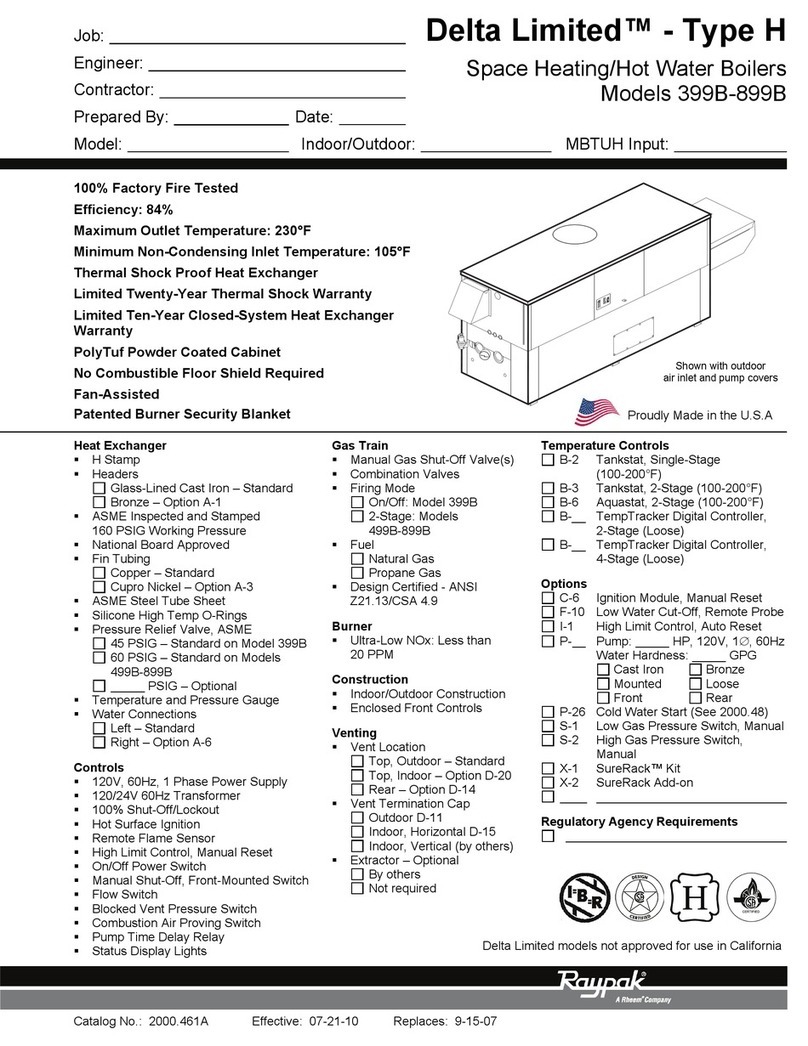
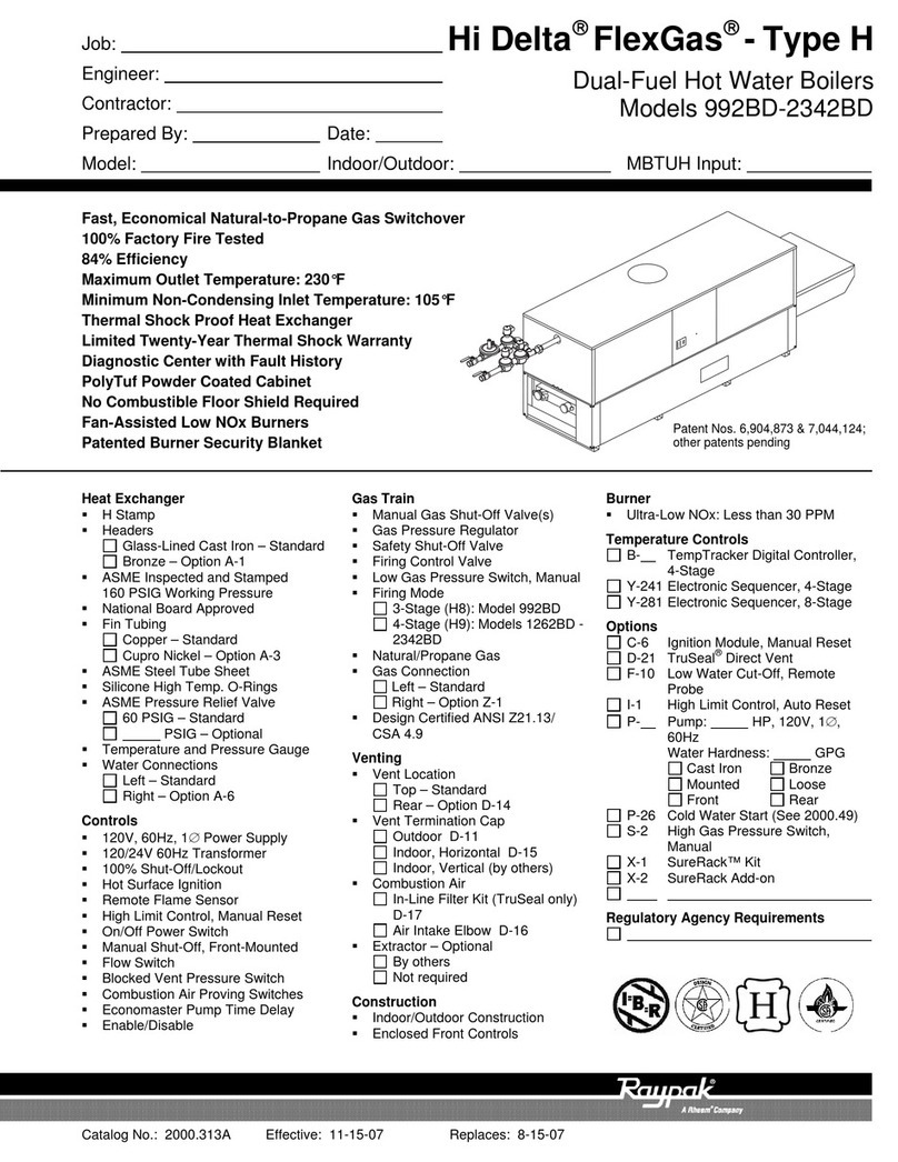
  9. Raypak FlexGas 302BD-2342BD User manual

Raypak FlexGas 302BD-2342BD User manual

This manual suits for next models

12

Other Raypak Boiler manuals

Raypak 500 Specification sheet

Raypak

Raypak 500 Specification sheet

Raypak XFyre 300A Manual

Raypak

Raypak XFyre 300A Manual

Raypak 1005-2005 User manual

Raypak

Raypak 1005-2005 User manual

Raypak XPAK 120 Manual

Raypak

Raypak XPAK 120 Manual

Raypak 180B User manual

Raypak

Raypak 180B User manual
Raypak 503-2003 User manual

Raypak

Raypak 503-2003 User manual

Raypak 241275 User manual

Raypak

Raypak 241275 User manual

Raypak RAYTHERM 133-4001 Manual

Raypak

Raypak RAYTHERM 133-4001 Manual

Raypak 399B-2339B Manual

Raypak

Raypak 399B-2339B Manual

Raypak HI DELTA HD101 THRU 2342B Guide

Raypak

Raypak HI DELTA HD101 THRU 2342B Guide

Raypak HI DELTA 302B Manual

Raypak

Raypak HI DELTA 302B Manual

Raypak 503A Manual

Raypak

Raypak 503A Manual

Raypak Xtherm 1005 Manual

Raypak

Raypak Xtherm 1005 Manual

Raypak XFYRE 500 Guide

Raypak

Raypak XFYRE 500 Guide

Raypak 302BE-902BE User manual

Raypak

Raypak 302BE-902BE User manual
Raypak 1005-2005 Manual

Raypak

Raypak 1005-2005 Manual

Raypak 88AR-398A Manual

Raypak

Raypak 88AR-398A Manual

Raypak 0090B 0135B User manual

Raypak

Raypak 0090B 0135B User manual
Raypak RAYTHERM H-0042 User manual

Raypak

Raypak RAYTHERM H-0042 User manual

Raypak MVB TYPE B 504-2004 Manual

Raypak

Raypak MVB TYPE B 504-2004 Manual

Raypak RAYTHERM 133 User manual

Raypak

Raypak RAYTHERM 133 User manual

Raypak Xtherm 1505A Manual

Raypak

Raypak Xtherm 1505A Manual

Raypak FlexGas 302BD User manual

Raypak

Raypak FlexGas 302BD User manual

Raypak Gas Fired Boiler Guide

Raypak

Raypak Gas Fired Boiler Guide

Popular Boiler manuals by other brands

IDEAL IMAX XTRA EL 320 user guide

IDEAL

IDEAL IMAX XTRA EL 320 user guide

UTICA BOILERS BC3D Installation, operation & maintenance manual

UTICA BOILERS

UTICA BOILERS BC3D Installation, operation & maintenance manual

Lochinvar SOLUTION 260000 Installation & service manual

Lochinvar

Lochinvar SOLUTION 260000 Installation & service manual

Weil-McLain EG 6 Series manual

Weil-McLain

Weil-McLain EG 6 Series manual

RBI LCD Series Installation & operation manual

RBI

RBI LCD Series Installation & operation manual

Baxi MainEco Combi 28 Installation and service manual

Baxi

Baxi MainEco Combi 28 Installation and service manual

Unical ALKON R 24 Installation and Servicing Manual

Unical

Unical ALKON R 24 Installation and Servicing Manual

Automatic Heating Gasogen Installation and Servicing Manual

Automatic Heating

Automatic Heating Gasogen Installation and Servicing Manual

Viessmann VITORADIAL 300-T Type VR3 Service instructions for contractors

Viessmann

Viessmann VITORADIAL 300-T Type VR3 Service instructions for contractors

Alpha GasSaver GS-1 Installation and servicing instructions

Alpha

Alpha GasSaver GS-1 Installation and servicing instructions

Baxi ROCA LAURA PLUS 28/28 Operating, cleaning and maintenance instructions for the user

Baxi

Baxi ROCA LAURA PLUS 28/28 Operating, cleaning and maintenance instructions for the user

Vaillant uniSTOR VIH SW GB 500 BES operating instructions

Vaillant

Vaillant uniSTOR VIH SW GB 500 BES operating instructions

Kärcher HWE 4000 Gas manual

Kärcher

Kärcher HWE 4000 Gas manual

Radijator BIO max 23.1 instruction manual

Radijator

Radijator BIO max 23.1 instruction manual

Granby BKC Installation, operation and maintenance manual

Granby

Granby BKC Installation, operation and maintenance manual

Brunner BSV 20 Instructions for use

Brunner

Brunner BSV 20 Instructions for use

Potterton 50e Installation and Servicing Manual

Potterton

Potterton 50e Installation and Servicing Manual

UTICA BOILERS TriFire Assembly instructions

UTICA BOILERS

UTICA BOILERS TriFire Assembly instructions

manuals.online logo
manuals.online logoBrands
  • About & Mission
  • Contact us
  • Privacy Policy
  • Terms and Conditions

Copyright 2025 Manuals.Online. All Rights Reserved.

SUPPLEMENTAL INSTALLATION AND
OPERATING INSTRUCTIONS
Catalog No. 1000.58B Effective: 06-24-08 Replaces: 02-22-07 P/N 241295 Rev. 3
Patent No. 6,904,873; Other patent pending
FOR YOUR SAFETY: Do not store or use gasoline or other flammable vapors and liquids
or other combustible materials in the vicinity of this or any other appliance. To do so may
result in an explosion or fire.
WHAT TO DO IF YOU SMELL GAS:
• Do not try to light any appliance.
• Do not touch any electrical switch; do not use any phone in your building.
• Immediately call your gas supplier from a neighbor's phone. Follow the gas supplier's
instructions.
• If you cannot reach your gas supplier, call the fire department.
Installation and service must be performed by a qualified installer, service agency or the gas
supplier.
This manual should be maintained in legible condition and kept adjacent to the heater or in another safe place for
future reference.
For Hi Delta Models
302BD–2342BD
FlexGas™
NOTE: THIS MANUAL IS SUPPLEMENTAL FOR THE FLEXGAS MODELS OF
THE HI DELTA HEATERS. THIS MANUAL ADDRESSES THE SPECIFIC DIF-
FERENCES BETWEEN THESE HEATERS AND STANDARD HI DELTA
MODELS. Please refer to the standard Installation and Operating Instruction manuals
(Catalogs 1000.501 and 1000.511 as appropriate) for installation requirements which are not
related to the gas supply.
2
Rev. 3 reflects the following: Changes to: step 4 of the FlexGas System Start-up section on page 7; the Wiring Diagram
was moved from page 5 to page 9; the addition of: a note to the Attach Manometers to Measure Pressures section on
page 7.
Raypak strongly recommends that this manual be
reviewed thoroughly before installing your Hi Delta
heater equipped with FlexGas. Raypak also recom-
mends that the appropriate Hi Delta Installation and
Operating Instruction manual (1000.501 for 302B-
902B or 1000.511 for 992B – 2342B) be thoroughly
read before attempting to install these heaters. Fac-
tory warranty does not apply to heaters that have been
improperly installed or operated. (Refer to the warran-
ty at the back of the standard Hi Delta manuals.)
Installation and service must be performed by a quali-
fied installer, service agency or gas supplier. If, after
reviewing these manuals, you still have questions
which these manuals do not answer, please contact
the manufacturer or your local Raypak representative.
Thank you for purchasing a Raypak product. We hope
you will be satisfied with the high quality and durability
of our equipment.
Model Identification
The model identification number and heater serial
number are found on the heater rating plate located on
the lower right outside jacket of the heater. The model
number will have the form H9 1262BD or similar
depending on the heater size and configuration. The
letter(s) in the first group of characters identifies the
application (H = Hydronic Heating, WH = Domestic
Hot Water (DHW), P = Pool). The number which fol-
lows identifies the firing mode (1 or 4 = on-off, 3 =
2-stage, 8 = 3-stage and 9 = 4-stage). NOTE: Not all
these firing options are available on all heaters.
Refer to the Hi Delta manual for available firing
options. The second group of characters identifies the
size of the heater (four numbers representing the
approximate MBTUH input), and, where applicable, a
letter, indicating the manufacturing series. The final
character is the letter “D” which designates the heater
as a FlexGas equipped heater.
Ratings and Certifications
Standards:
• ANSI Z21.13 · CSA 4.9 - latest edition, Gas-Fired
Hot Water Boilers
• CAN 3.1 - latest edition, Industrial and Commer-
cial Gas-Fired Package Boilers
• ANSI Z21.56 · CSA 4.7 - latest edition, Gas-Fired
Pool Heaters
• ANSI Z21.10.3 · CSA 4.3 - latest edition, Gas
Water Heaters
3
WARNING: Do not use this heater if any part has
been under water. Immediately call a qualified serv-
ice technician to inspect the heater and to replace
any part of the control system and any gas control
which has been under water.
WARNING: Should overheating occur or the gas
supply valve fail to shut off, do not turn off or discon-
nect the electrical supply to the heater. Instead, shut
off the gas supply at a location external to the heater.
WARNING: Risk of electrical shock. More than one
disconnect switch may be required to de-energize
the equipment before servicing.
WARNING: This FlexGas heater is intended for
operation on Natural Gas as the primary fuel. DO
NOT use this heater on Propane Gas as the primary
fuel.
Model Input
(MBTUH)
Pipe Size
(Nat)
Pipe Size
(LP)
302BD 300 1-1⁄4”3⁄4”
402BD 399 1-1⁄4”3⁄4”
502BD 500 1-1⁄4”3⁄4”
652BD 650 1-1⁄4”3⁄4”
752BD 750 1-1⁄4” 1-1⁄4”
902BD 900 1-1⁄4” 1-1⁄4”
992BD 990 2” 1-1⁄4”
1262BD 1260 2” 1-1⁄4”
1532BD 1530 2” 1-1⁄4”
1802BD 1800 2” 1-1⁄4”
2072BD 2070 2” 1-1⁄4”
2342BD 2340 2” 1-1⁄4”
Table 1: FlexGas Specifications
4
All Raypak heaters are National Board Approved, and
design-certified and tested by the Canadian Stan-
dards Association (CSA) for the U.S. and Canada.
Each heater is constructed in accordance with Section
IV of the American Society of Mechanical Engineers
(ASME) Pressure Vessel Code, and bears either the
ASME “H” stamp for boilers or “HLW” stamp for water
heaters. The heater also complies with the latest edi-
tion of ASHRAE 90.1 Standard.
Rated inputs are suitable for up to 4,500 ft elevation
without de-rating. Consult the factory for installations
at altitudes over 4,500 ft above sea level.
Component Locations
Installation Codes
Installations must follow these codes:
• Local, state, provincial, and national codes, laws,
regulations and ordinances
• National Fuel Gas Code, ANSI Z223.1/NFPA 54 –
latest edition (NFGC)
• National Electrical Code, ANSI/NFPA 70 - latest
edition (NEC)
For Canada only: CAN/CGA B149 Installation Code
(B149.1) and CSA C22.1 C.E.C. Part 1 (C22.1)
Gas Supply
This heater will be connected to 2 different gas sup-
plies (Natural Gas and Propane Gas).
Each gas piping must have a separate sediment trap
ahead of the gas controls. Pounds-to-inches regula-
tors must be installed to reduce the gas supply
pressure to a maximum of 10.5 in. WC for natural gas
and 13.0 in. WC for propane gas. The regulator should
be placed a minimum distance of 10 times the pipe
diameter upstream of the heater gas controls.
The heater must be isolated from the gas supply pip-
ing system by closing the manual shut-off valves
during any pressure testing of the gas supply piping
system at test pressures equal to or less than 1/2 psi
(3.45 kPa). Relieve test pressure in the gas supply line
prior to reconnecting the heater and its manual shut-off
valves to the gas supply lines. FAILURE TO FOLLOW
THIS PROCEDURE MAY DAMAGE THE GAS
VALVES. Over-pressurized gas valves are not cov-
ered by warranty. The heater and its gas connections
shall be leak-tested before placing the appliance in
operation. Use soapy water for leak test. DO NOT use
an open flame.
WARNING: Altering any Raypak pressure vessel
by installing replacement heat exchangers, tube
bundle headers, or any ASME parts not manufac-
tured and/or approved by Raypak will instantly void
the ASME and CSA ratings of the vessel and any
Raypak warranty on the vessel. Altering the ASME or
CSA ratings of the vessel also violates national,
state, and local approval codes.
Fig. 1: Component Locations – Back
CAUTION: The heater must be disconnected from
the gas supply during any pressure testing of the gas
supply system at test pressures in excess of 1/2 psi
(3.45 kPa).
FlexGas cover not shown for clarity
NOTE: Maintain upright orientation of all compo-
nents as shown in Fig. 1.
5
Gas Supply Pressure
A minimum of 5.0 in. WC and a maximum of 10.5 in.
WC upstream gas pressure is required under load and
no-load conditions for natural gas. A minimum of 8.0
in. WC and a maximum of 13.0 in. WC is required for
propane gas. The gas pressure regulator(s) supplied
on the heater is for low-pressure service. If upstream
gas pressures exceed 14.0 in. WC, intermediate gas
pressure regulators, of the lockup type, must be
installed.
When connecting additional gas utilization equipment
to the gas piping system, the existing piping must be
checked to determine if it has adequate capacity for
the combined load.
The gas valve pressure regulator(s) on the Hi Delta
heater are nominally preset at 3.5 in. WC. The pres-
sure regulator on the FlexGas propane system is
nominally set at 2.2 ± 0.1 in. WC. This can be verified
by measuring the propane gas pressure at the upper
manifold pressure tap shown in Fig. 5. The pressure at
the gas valve(s) outlet tap, measured with a manome-
ter, while in operation should be 3.5 ± 0.1 in. WC for
natural gas. A nominal pressure of 1.3 in. WC will be
observed at the individual heater gas valve outlet taps
on propane gas. See Fig. 5 for gas pressure measure-
ment locations.
Bleeds/Vents
This FlexGas gas train is equipped with an propane
gas regulator and low gas pressure switch (optional on
302BD-902BD) which may need to be vented to the
outdoors as required by state and local codes. If these
components are required to be vented, the cover must
be removed and vent lines installed into the compo-
nents and ran to a suitable location outside the
building in compliance with the NFGC. See Fig.3.
CAUTION: Do not use Teflon tape on gas line pipe
thread. A pipe compound rated for use with natural
and propane gases is recommended. Apply sparing-
ly only on male pipe ends, leaving the two end
threads bare.
CAUTION: Support gas supply piping with hang-
ers, not by the heater or its accessories. Make sure
the gas piping is protected from physical damage
and freezing, where required.
Low Gas Pressure Switch
(Optional on 302BD-902BD)
Fig. 2: Gas Supply Connection - Top View
NOTE: DO NOT adjust the FlexGas propane regu-
lator setting without verifying proper operation
including the use of a flue gas analyzer.
Fig. 3: FlexGas Cover Removal & Vent Locations
CAUTION: DO NOT adjust the individual heater
gas valve pressure settings when firing with
propane gas. Propane adjustments (if neces-
sary) should ONLY be made to the FlexGas
propane regulator.
6
Start-up
For Your Safety
This appliance has a hot surface igniter(s). It is
equipped with an ignition device(s) which automatical-
ly lights the burners. Do not try to light the burners by
hand.
BEFORE OPERATING, smell all around the appli-
ance area for gas. Be sure to smell near the floor
because some gas is heavier than air and will settle on
the floor.
WHAT TO DO IF YOU SMELL GAS:
• Do not try to light any appliance.
• Do not touch any electrical switch; do not use any
telephone in your building.
• Immediately call your gas supplier from a neigh-
bor’s telephone. Follow the gas supplier’s
instructions.
• If you cannot reach your gas supplier, call the fire
department.
• Use only your hand to push in or turn the gas con-
trol knob. Never use tools. If the knob will not turn
by hand, do not try to repair it, call a qualified serv-
ice technician. Forced or attempted repair may
result in a fire or explosion.
• Do not use this appliance if any part has been
under water, immediately call a qualified service
technician to inspect the appliance and to replace
Initial Start-up
Tools Needed:
• (1) 12-0-12, 24” scale U-tube manometer
• (4) 6-0-6, 12” scale U-tube manometers (min.)
• (1) Screwdriver
• (1) Multi-meter
• (1) 3/16” Allen wrench
WARNING: If you do not follow these instructions
exactly, a fire or explosion may result causing prop-
erty damage, personal injury or loss of life.
NOTE: Digital manometers are not recommended.
any part of the control system and any gas control
which has been under water.
• Check around unit for debris and remove combus-
tible products, i.e. gasoline, etc.
Pre Start-up Check
1. Verify heater is filled with water.
2. Check system piping for leaks. If found, repair
immediately.
3. Vent air from system. Air in system can interfere
with water circulation.
4. Purge air from gas lines up to FlexGas gas train.
Propane Supply Pressure
Test Point
Models: 302BD-902BD Models: 992BD-
2342BD
Gas Valve
Output Tap
Fig. 4: FlexGas Gas Pressure Measurement Locations
7
Preparation
Check Power Supply
With multi-meter at incoming power in Hi Delta heater,
check voltage between:
Hot - Common (≈120 VAC)
Hot - Ground (≈120 VAC)
Common - Ground (< 1 VAC)
Attach Manometers to Measure Pressures
1. Turn off main gas valves.
2. Attach 24” scale manometer to the first main gas
shut-off valve pressure tapping.
3. Attach (1) 12” scale manometer to the outlet side
of the second main gas shut-off valve pressure
tapping.
4. Attach (1) 12” scale manometer near the fan-prov-
ing switch. Pull black cap from air pressure switch
tee and connect the manometer. NOTE: Retain
caps for reinstallation later.
Check Gas Supply Pressure
1. Slowly turn on main gas shut-off valve.
2. Read the gas supply pressure from the manome-
ter; minimum supply pressure for natural gas is 5.0
in. WC, recommended supply is 7.0 in. WC, mini-
mum supply pressure for propane gas is 8.0 in.
WC (dynamic readings, all stages firing).
3. If the pressure is > 14.0 in. WC, turn off the valve.
4. Check if the service regulator is installed and/or
adjust the service regulator.
FlexGas System Start-up
1. Turn off unit. Ensure that the switch on the
FlexGas control is in the position marked “NAT”.
See Fig. 6 for FlexGas control operation. Ensure
the manual valve on the natural gas supply is open
and the manual valve on the propane supply is
closed.
2. Turn on the unit, wait 15 seconds, and the igniter
should glow. Look into sight glass located at each
end of the heater to check igniter operation. Gas
valves should open in 45-60 seconds.
3. If burner does not light on first trial. It will retry, up
to three times.
4. Main burner ignition: Check manifold gas pres-
sure at gas valve outlet pressure tap. This should
read 3.5 ± 0.1 in. WC for natural gas. If the natural
gas manifold pressure is not within 3.5 ± 0.1 in.
WC, follow the instructions in the Hi Delta I&O
manual for adjusting manifold pressure. If a flue
gas analyzer is used, the CO2 on natural gas
should be 7.5-8.5% and CO should be less than
150 ppm.
5. When acceptable operation on Natural Gas is con-
firmed, turn the gas selector key on the FlexGas
control to “OFF”.
6. Close the manual valve on the natural gas supply
then open the manual valve on the propane sup-
ply. When the heater shuts off, turn the FlexGas
control key counter-clockwise to the “PRO” posi-
tion.
7. Wait 15 seconds, and the igniter should glow. Look
into sight glass located at each end of the heater
to check igniter operation. Gas valves should open
in 45-60 seconds.
WARNING: This FlexGas heater is intended for
operation on Natural Gas as the primary fuel. DO
NOT use this heater with Propane Gas as the pri-
mary fuel.
NOTE: Do not adjust Hi Delta valve(s) or manifold
settings when operating on propane. These should
only be adjusted while firing natural gas.
WARNING: Do not turn on gas at this time.
WARNING: If Common - Ground is > 1 VAC,
STOP: Contact electrician to correct ground failure.
Failure to do this may burn out 120V-24V trans-
former, or may cause other safety control damage or
failure.
NOTE: The fan(s) pressure is already factory set to
1.4 in. ± .1 in. WC (up to 4500 ft altitude). If adjust-
ment(s) is required, consult the appropriate Hi Delta
manual.
From PRO to NAT:
1. Turn the boiler off (power switch on front control
panel).
2. Turn FlexGas key to “OFF”.
3. Close PRO manual valve.
4. Open NAT manual valve.
5. Turn FlexGas key to “NAT”.
6. Turn the boiler on.
Safety Inspection
1. Check all thermostats and high limit settings.
2. During the following safety checks leave ma-
nometers hooked up, check and record.0
3. If other gas-fired appliances in the room are on the
same gas main, check all pressures on the Hi
Delta with all other equipment running.
4. Check thermostats for ON-OFF operation.
5. Check high limits for ON-OFF operation.
6. While in operation, check flow switch operation.
7. Check the low gas pressure switch. (For proper
adjustment, use the attached manometers, if
available, to set pressure. The scales on the
switch are approximate only.) Low gas pressure
switch (if equipped) must be set at 5.0 in. WC for
natural gas.
Follow-Up
Safety checks must be recorded as performed.
Turn heater on. After main burner ignition:
1. Check manometer for proper reading.
2. Cycle heater several times and re-check readings.
3. Turn unit off.
8
8. If burner does not light on first trial. It will retry, up
to three times.
9. Main burner ignition: Check upper manifold gas
pressure.
10. If the pressure readings differ by more than ± 0.1
in. WC, remove screw cover from the gas pres-
sure regulator on the FlexGas fuel train and adjust
until upper manifold pressure is nominally 2.2 ±
0.1 in. WC (manifold pressure 1.3 ± 0.1 in. WC). If
a flue gas analyzer is used, the CO2 on propane
should be 9.0-10.0% and CO should be less than
150 ppm.
11. Replace the screw cover.
12. Turn the gas selector key on the FlexGas control
panel to “OFF”.
13. Close the manual valve on the propane gas supply
and open the manual valve on the natural gas
supply. Turn the gas selector key on the FlexGas
control clockwise to “NAT”. The heater is now
ready for operation.
FlexGas Operation - Changing Fuels
From NAT to PRO:
1. Turn the boiler off (power switch on front control
panel).
2. Turn FlexGas key to “OFF”.
3. Close NAT manual valve.
4. Open PRO manual valve.
5. Turn FlexGas key to “PRO”.
6. Turn the boiler on.
NOTE: Reset Low Gas Pressure Switch (when
equipped) if necessary. Refer to Fig. 2 for location.
CAUTION: Special manifold and air settings may
be required. Verify rating plate and blower housing.
CAUTION: Once the natural gas pressures are
established, DO NOT adjust the Hi Delta gas valves
to attain the required propane pressures.
Adjustments must be made to the FlexGas propane
regulator.
9
4. Remove all manometers and replace caps and
screws.
5. Replace all gas pressure caps.
6. Check for gas leaks one more time.
7. Restart unit.
Fig. 5: FlexGas Control Panel
Fig. 6 Wiring Diagram
*
*Optional on
302BD–902BD
Wiring Diagram
10