RaySafe i2 Instruction Manual

Service Manual
RaySafe i2
Installation and maintenance

© 2013.01 Unfors RaySafe 5001050-C
All rights are reserved. Reproduction or transmission in whole or in part, in any form or by any means,
electronic, mechanical or otherwise, is prohibited without the prior written consent of the copyright owner.

3
RaySafe i2 Installation and maintenance manual – Contents
CONTENTS
INTRODUCTION .....................................................................................................4
About the RaySafe i2 System ..........................................................................4
How the system works ................................................................................... 5
About this user manual................................................................................... 5
INSTALLATION....................................................................................................... 6
Package contents ........................................................................................... 6
Real time display installation...........................................................................7
Dose viewer installation ................................................................................ 17
Dose manager installation............................................................................. 19
Dosimeter and dosimeter rack..................................................................... 20
SYSTEM FUNCTION TESTS ................................................................................. 23
Expose dosimeter to radiation..................................................................... 23
Dose viewer/dose manager test ................................................................. 23
Real time display test ................................................................................... 24
MEASUREMENT PERFORMANCE VERIFICATION................................................ 26
SOFTWARE UPDATE AND MAINTENANCE...........................................................27
Real time display software update ...............................................................27
Dose viewer software update ......................................................................27
Dose manager software update ................................................................. 28
Real time display touch screen re-calibration ............................................ 28
TECHNICAL DATA ............................................................................................... 29
Real time display .......................................................................................... 29
Dosimeter ..................................................................................................... 29
Cradle ........................................................................................................... 30
Dosimeter rack ............................................................................................. 30
Radio communication .................................................................................. 30
Climatic conditions ........................................................................................ 31
INSTALLATION SETTINGS FORM......................................................................... 32

4
RaySafe i2 Installation and maintenance manual – Introduction
INTRODUCTION
ABOUT THE RAYSAFE i2 SYSTEM
Figure 1. RaySafe i2 System overview
The RaySafe i2 System can contain the following components:
• dosimeter
• real time display
• dose viewer (computer software)
• dose manager (computer software)
• cradle (dock station used to connect dosimeters and computer)
• dosimeter rack (dosimeter storage)

5
RaySafe i2 Installation and maintenance manual – Introduction
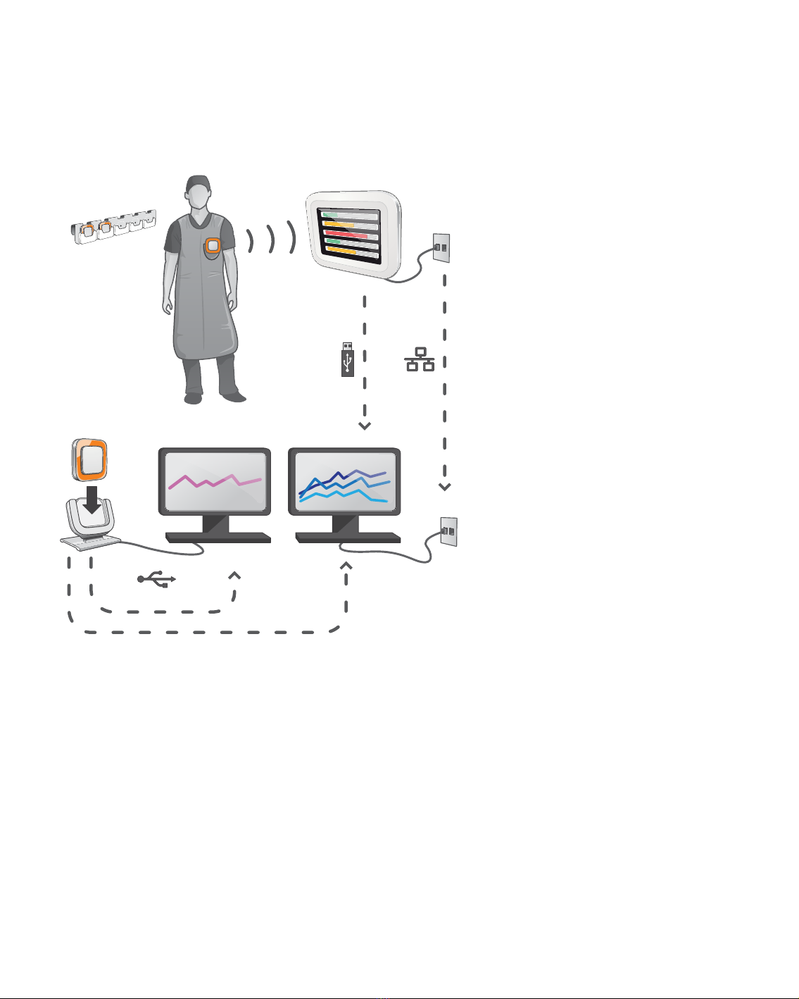
HOW THE SYSTEM WORKS
The dosimeter measures and records X-ray exposure every second and transfers the data wirelessly, via radio,
to the real time display.
The real time display shows real time dose exposure from up to eight dosimeters in range. Color indication
bars (green, yellow, red) represents the intensity of the currently received exposure. The accumulated dose
per individual is displayed next to the color indication bars. By tapping a dosimeter name the user can look at
historical data in separate views.
When the dosimeter is not in use, it should be stored in the dosimeter rack, away from the real time display.
More detailed historical dose information can be transferred from dosimeters via the cradle connected to a
computer and viewed using the computer software (dose viewer and dose manager).
The dose viewer software is also used for administrating dosimeters, change dosimeter names, colors and
reset dose history. The dose manager software is an advanced software for analyzing, reporting and archiving
dose information. It handles multiple dosimeters and can retrieve the dose information from multiple real time
displays through the hospital network or via USB storage.
ABOUT THIS USER MANUAL
This user manual are intended to assist users in the safe and eective operation of the product described.
Before attempting to operate the product, you must read these instructions for use, noting and strictly
observing all WARNINGS and CAUTION notices.
WARNING A WARNING alerts you to a potential serious outcome, adverse event or safety hazard. Failure
to observe a warning may result in death or serious injury to the operator or patient.
CAUTION A CAUTION alerts you to where special care is necessary for the safe and eective use of
the product. Failure to observe a caution may result in minor or moderate personal injury or
damage to the product or other property, and possibly in a remote risk of more serious injury,
and/or cause environmental pollution.
NOTE Notes highlight unusual points as an aid to an operator.
These Instructions for Use describe the most extensive configuration of the product, with the maximum number
of options and accessories. Not every function described may be available on your product.

6
RaySafe i2 Installation and maintenance manual – Installation
INSTALLATION
PACKAGE CONTENTS
NOTE: The content is dependent of purchased configuration.
RAYSAFE i2 PACKAGE
• RaySafe i2 real time display
• Real time display power supply
• Power plug adapters: EU, UK, US, MCS
• Tie wraps, short (L200) and long (L300)
• VESA LCD wall holder
• 4 x RaySafe i2 dosimeter
• RaySafe i2 dosimeter Calibration Certificate
• RaySafe i2 cradle
• RaySafe i2 dosimeter rack
• RaySafe i2 dose viewer software and manuals
• Radiation protection poster
• RaySafe i2 installation and service manual
RAYSAFE i2 DOSE MANAGER PACKAGE
Extension package.
• RaySafe i2 dose manager software and manuals
• RaySafe i2 dose manager license key
• RaySafe i2 cradle
NOTE: Ethernet cable (for network connection of the real time display) is not included.

7
RaySafe i2 Installation and maintenance manual – Installation
REAL TIME DISPLAY INSTALLATION
WARNING: Switch o the system before starting any installation or replacement activities.
NOTE: The real time display is delivered with the required software installed.
NOTE: In multiple real time display setups, the individual real time displays should be placed in
separate rooms.
NOTE: The user’s software version may dier from the one on the screenshots in the manual, without
any change in functionality.
REQUIRED TOOLS
The following tools are required for mounting the real time display on a wall:
• one 8 mm masonry drill or one 3 mm wood drill
• one medium sized cross headed screwdriver
• one medium sized slotted screwdriver

8
RaySafe i2 Installation and maintenance manual – Installation
REAL TIME DISPLAY INTERFACES
21 3
4
Figure 2. The real time display interfaces: 1: 12 V DC, 2: ethernet connection, 3: USB connection, 4: VESA
75 interface
MOUNT THE REAL TIME DISPLAY
The wall support kit contains:
• one VESA 75 wall mounting plate
• one VESA 75 real time display mounting plate
• fixation screws and plugs for the wall mounting plates
Follow the steps below to mount the real time display on a wall:
1. Mount the VESA 75 real time display mounting plate to the real time display using the screws provided with
the real time display. Use 8 washers.
2. Place the VESA 75 wall mounting plate on the wall and mark the location of the mounting screws through
the plate’s mounting holes.

9
RaySafe i2 Installation and maintenance manual – Installation
3. Drill the holes as marked, using the masonry or wood drill as appropriate.
4. Mount the VESA 75 wall mounting plate to the wall using the provided screws and plugs.
5. Position the real time display with its mounting plate on the wall mounting plate.
POWER SUPPLY
A 12V power adaptor (Astec DPS53-M, FW7556M/12) powers the real time display.
Insert the output connector of the power adaptor to the back of the real time display, and the AC power cable
to a grounded electrical outlet socket.
You may use the included tie wraps to attach the power adaptor if needed.
WARNING To avoid the risk of electric shock, the real time display must only be connected to a supply
mains with protective earth.
CAUTION: The real time display battery should not be replaced due to risk of explosion if it is replaced by
an incorrect type.
CAUTION: The electrical outlet socket should be near the real time display and shall be easily accessible.
ETHERNET INTERFACE
The ethernet interface is used together with the dose manager application only.
Perform the following steps to connect the real time display to the hospital network:
1. Connect an ethernet cable (not included in the package) to the hospital’s network.
2. Connect the ethernet cable to the ethernet connector at the back of the real time display.
CONFIGURE THE REAL TIME DISPLAY
Follow the instructions below to enter the real time display settings view:
1. Tap the settings menu symbol in the upper left corner of the online view.
2. Enter configuration values by tapping the buttons in the respective menus.
NOTE: Make all real time display set-up configurations in the system settings menu.

10
RaySafe i2 Installation and maintenance manual – Installation
USER SETTINGS MENU
Figure 3. The user settings menu consists of one screen.
Adjust the backlight level of the screen by moving the bar horizontally.
This change will take eect immediately.

11
RaySafe i2 Installation and maintenance manual – Installation
ADMIN SETTINGS MENU
The admin settings menu consists of four screens. Access these screens by tapping the arrow buttons in the
lower right corner of each screen.
Real time display name and location menu
Figure 4. The real time display name and location menu.
Enter appropriate name and location of the real time display. This information is used to identify the real time
display so that it can be found in dose manager.
Enter service contact name and number to your local RaySafe i2 system manager.
Figure 5. The notification area in the personal dose overview
The service contact information will appear in the notification area, on the left side in the personal dose
overview.

12
RaySafe i2 Installation and maintenance manual – Installation
Reserved slots menu
Figure 6. The reserved slots menu.
This is an optional setting, which you can use to reserve a number of slots in the online view for the clinical
roles doctor, nurse and technician. If you, for example, have reserved three slots for doctors but the real time
display detects only one, there will be two empty slots before the first nurse appears.
If you want to reserve slots for nurses, you also have to reserve slots for doctors. If you want to reserve slots for
technicians, you also have to reserve slots for doctors and nurses.
The default behavior “Auto” is first-come, first-served, which means that dosimeters will appear on the screen
in the order the real time display detects them, sorted after their clinical role: doctor, nurse, technician, other.
This is the recommended setting.

13
RaySafe i2 Installation and maintenance manual – Installation
Network setup menu
Figure 7. The network setup menu.
Configure the network connection between the real time display and the dose manager. You might have to
contact the local IT department to receive the IP address.
If you change this information, the real time display requires a restart.
NOTE: Network setup is only applicable if you are using the dose manager software.

14
RaySafe i2 Installation and maintenance manual – Installation
Time and date menu
Figure 8. The time and date menu.
Set time, date, time zone and manage daylight saving time for the real time display.
For daylight saving time, you can select to manage it manually or by selecting a daylight settings region for
your time zone. The possible regions available for daylight saving time are dierent depending on your current
time zone.
If you choose to manage daylight saving time manually, you can choose to set it to wintertime (+0 hours)
or summer time (+1 hours). If a region is selected, the change between winter/summer time will be done
automatically.

15
RaySafe i2 Installation and maintenance manual – Installation
SYSTEM SETTINGS MENU
The system settings menu consists of three screens. Access these screens by tapping the arrow buttons in the
lower right corner of each screen.
Touch screen menu and dose
Figure 9. The touch screen and dose menu.
If the touch screen is disabled in the online view; enable it by checking the touch screen check box.
NOTE: The settings button and menu is always active.
Follow the instructions below to synchronize the dose history that is stored in the real time display to a USB
memory:
1. Insert a USB memory at the back of the real time display.
2. Press the button Sync to USB. The synchronization will start. This may take a while, depending on how
much data that is stored in the real time display. Reset the dose history stored in the real time display by
pressing the button Reset.

16
RaySafe i2 Installation and maintenance manual – Installation
Check the box Show accumulated procedure dose to show a column with the accumulated dose since last tap
on the reset button in the lower right corner of the online view. The accumulated dose per examination will also
be reset when restarting the real time display.
NOTE The accumulated dose per examination is only recorded in the real time display memory. The
values recorded in the dosimeter is not aected.
Check the box Show units in rem instead of Sv if you want to view all measurements in rem. (Conversion factor
1 Sv = 100 rem is used.)
DOSIMETER COMMUNICATION RANGE MENU
Figure 10. The dosimeter communication range menu.
In Lab is the default communication range setting. If you have problem with the communication between
dosimeter and real time display, change the range.
• If you have several real time displays and dosimeters show up on an undesired display, select Nearby.
• If you have trouble with dosimeters not showing up on the desired display, try the Maximum Range setting.

17
RaySafe i2 Installation and maintenance manual – Installation
NOTE: To prevent dosimeters not currently in use to show up on a real time display, the dosimeter
rack should be located preferably more than 10 meters away from the real time display and
not in line of sight.
LANGUAGE MENU
Figure 11. The language menu.
Follow the instructions below to change the language in the real time display:
1. Choose your preferred language. The change will take eect after a restart, see steps 2–3 below
2. Disconnect the power supply.
3. Re-connect the power supply.
DOSE VIEWER INSTALLATION
SYSTEM REQUIREMENTS
• Operating systems: Windows 7, Windows Vista or Windows XP
• .NET 3.0

18
RaySafe i2 Installation and maintenance manual – Installation
• One USB port available
• 1 GB of system memory available
• 40 GB hard drive with at least 15 GB of memory available
• Recommended screen resolution at least 1024 x 768
INSTALLATION
Follow the instructions below to install the dose viewer application and the cradle driver:
NOTE: Do not connect the cradle to the computer until dose viewer is properly installed.
1. Log on as local administrator on the computer on which to install dose viewer.
2. Insert the dose viewer CD into the computer’s CD drive. The dose viewer install wizard will start
automatically.
3. Follow the instructions on the screen.
4. Check the box “Launch dose viewer” to start the dose viewer application. The installation procedure will
finish by creating a dose viewer icon on the desktop.
5. Connect the cradle to the computer using the USB cable. Dose viewer will detect the cradle within 30
seconds.
TROUBLESHOOTING
If the installation procedure fails, verify that:
• the system requirements are met.
• you are logged on as local administrator.
• there is no previous version of dose viewer installed on the computer (see “Dose viewer software update”
on page 27).
If Windows does not automatically install the cradle driver when the cradle is first connected to a PC, you need
to install it manually. All the driver files are located on the installation CD in the folder “CradleDriver”. These
files are also copied to the application installation folder when dose viewer is installed. When Windows detect
a connected cradle and the dialog about driver installation is displayed, select to use the driver files located on
the CD or in the application installation folder.

19
RaySafe i2 Installation and maintenance manual – Installation
DOSE MANAGER INSTALLATION
SYSTEM REQUIREMENTS
• Operating systems: Windows 7, Windows Vista or Windows XP
• .NET 3.5
• One USB port available
• 2 GB of system memory available
• 40 GB hard drive with at least 15 GB of memory available
• Recommended screen resolution at least 1280 x 1024
INSTALLATION
Dose manager and real time display are connected using the local hospital network. A network connection can
also be established using a crossed TP cable.
Follow the instructions below to install the dose manager application and the cradle driver:
NOTE: Do not connect the cradle to the computer until the cradle driver is installed.
1. Log on as local administrator on the computer on which to install dose manager.
2. Insert the dose manager CD into the computer’s CD drive. The dose manager install wizard will start
automatically.
3. Insert the license key that is written on the label on the dose manager box.
4. Follow the instructions on the screen.
5. Check the box “Launch dose manager” to start the dose manager application. The installation procedure
will finish by creating a dose manager icon on the desktop.
6. Connect the cradle to the computer using the USB cable. Dose manager will detect the cradle within 30
seconds.
7. Connect real time display and dose manager to the hospital network or directly connect them via a crossed
TP cable.
TROUBLESHOOTING
If the installation procedure fails, verify that:

20
RaySafe i2 Installation and maintenance manual – Installation
• the system requirements are met.
• you are logged on as local administrator.
• there is no previous version of dose manager installed on the computer (see “Dose manager software
update” on page 28).
If Windows does not automatically install the cradle driver when the cradle is first connected to a PC, you need
to install it manually. All the driver files are located on the installation CD in the folder “CradleDriver”. These
files are also copied to the application installation folder when dose manager is installed. When Windows
detect a connected cradle and the dialog about driver installation is displayed, select to use the driver files
located on the CD or in the application installation folder.
DOSIMETER AND DOSIMETER RACK
Check with the local organization where the dosimeters will be stored, this must be a location outside the X-ray
room to prevent registration of X-ray dose when not in use. A dosimeter rack provides room for 5 dosimeters
and can be mounted on the wall of for example the control room.
Figure 12. The dosimeter rack mounting
1. Mount the rack with 2 screws to the wall.
2. Clip-on the dosimeters.
NOTE To prevent dosimeters not currently in use to show up on a real time display, the dosimeter
rack should be located preferably more than 10 meters away from the real time display and
not in line of sight.
Table of contents
Other RaySafe Medical Equipment manuals
Popular Medical Equipment manuals by other brands

Acutronic Medical Systems
Acutronic Medical Systems fabian HFO quick guide

Smiths Medical
Smiths Medical Portex Blue Line Ultra Instructions for use

Invacare
Invacare C426AB user manual

Tesmed
Tesmed MAX 830 QUICK USER GUIDE AND USEFUL TIPS

Rigel Medical
Rigel Medical 288+ user manual

Armedica
Armedica AM Series manual