RaySafe i3 Supplement

INSTALLATION & SERVICE MANUAL
RaySafe i3
– with on-screen display

© 2019.10 Unfors RaySafe 5001121-1.00
All rights are reserved. Reproduction or transmission in whole or in part, in any form or by any means, electronic,
mechanical or otherwise, is prohibited without the prior written consent of the copyright owner.

3
RaySafe i3 Installation & service manual – Contents
ABOUT THE RAYSAFE i SYSTEM..............................................
PREPARATIONS ..........................................................................
Pre-installation checklist......................................................
System passwords...............................................................
Package contents ................................................................
System requirements for Dose Viewer ...............................
System requirements for Dose Manager............................
Learn more...........................................................................
INSTALLATION............................................................................
Dose Viewer.........................................................................
Initiate a Real-time Dosimeter.............................................
Initiate the Reference Dosimeter ......................................
Mount the Real-time Dosimeter Rack ...............................
Connection overview.........................................................
Mount the Video Unit.........................................................
Mount the Real-time Hub ..................................................
Connect the Power over Ethernet unit..............................
Configure the Video Unit...................................................
Configure the Real-time Hub.............................................
Mount the reference dosimeter ........................................
SYSTEM FUNCTION TESTS ......................................................
Real-time View test ...........................................................
Dose Viewer test ..............................................................
Communication Range Test ..............................................
REALTIME VIEW EXPLAINED ...................................................
MAINTENANCE AND SOFTWARE UPDATE...............................
Dosimeter battery replacement ........................................
Dose Viewer software update...........................................
Real-time hub software update.........................................
Cleaning.............................................................................
DATA EXPORT...........................................................................
Exposures...........................................................................
Sessions .............................................................................
Seconds .............................................................................
Dosimeter info ...................................................................
SETTINGS EXPLAINED..............................................................
Video unit...........................................................................
Real-Time Display ..............................................................
TROUBLESHOOTING................................................................
Measurement performance verification............................
TECHNICAL DATA ....................................................................
Real-time Dosimeter..........................................................
Real-time Hub ....................................................................
Video Unit ..........................................................................
Real-time Dosimeter Rack ................................................
Climatic conditions ............................................................
CONTENTS

4
RaySafe i3 Installation & service manual – About the RaySafe i3 System
ABOUT THE RAYSAFE i3 SYSTEM
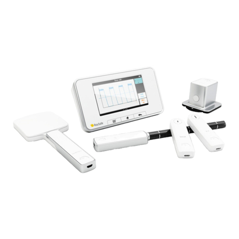
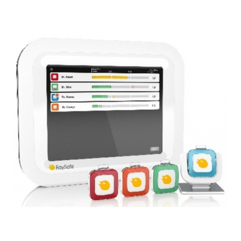
RaySafe i3 is designed for personal use on hospital sta. It measures scattered radiation in examination rooms using a
dosimeter, and shows a graphical visualization of dose rate in real time on a display.
2
3
4
87
6
5
1
Figure 1. 1: Real-time View, 2: Reference Dosimeter, 3: Real-time Dosimeter, 4: Dosimeter Rack, 5: Video Unit,
6: Real-time Hub, 7: Dose Manager software, 8: Dose Viewer software.
The dosimeters measure radiation and store measurements. When a dosimeter is in range of a Real-time Hub,
it automatically connects to the hub via radio. When a dosimeter is connected via radio to a Real-time Hub,
measurements are transferred once per second and are displayed as dose rate bars, low to high dose rate: green,
yellow or red.
All measurements recorded while connected to a Real-time Hub are saved in the hub and can be exported later in
dierent formats.
To view the measurements stored in a dosimeter, connect the dosimeter to a computer running Dose Viewer. Dose
Viewer can also be used for changing dosimeter settings, such as displayed name and annual dose limit.
Dose Manager is an optional analysis software.
RAYSAFE i3 IN A SIEMENS LAB
For installations in a Siemens lab:
• The reference dosimeter and the reference dosimeter holder shall not be used.
• When configuring the Real-time Hub, leave the field for reference dosimeter serial number blank.
NOTE: When no reference dosimeter is present in the system, there will be no history dose rate bars at the
right side of the screen.

5
RaySafe i3 Installation & service manual – Preparations
PREPARATIONS
The installation process may take a few hours.
PREINSTALLATION CHECKLIST
During the installation, you will need the following information.
Reference dosimeter serial number: Printed on the back side of the reference dosimeter.
Real-time Hub IP address1:From the hospital’s IT department.
Video Unit IP address1:From the hospital’s IT department.
Subnet mask: From the hospital’s IT department.
Default gateway: From the hospital’s IT department.
DNS server2(recommended): From the hospital’s IT department.
NTP12(recommended): From the hospital’s IT department.
NTP22(recommended): From the hospital’s IT department.
1) You might need to provide MAC addresses for the Video Unit and the Real-time Hub to the hospital’s IT department.
MAC addresses are printed on the back side of the products.
2) If you want to use NTP servers defined by hostnames, you also need the IP address of a DNS server and the names
of the NTP servers.
SYSTEM PASSWORDS
During the installation, you will also be prompted to enter new passwords for signing in. You can document the new
passwords for your system here.
Video Unit password:
Real-time Hub, Data export password:
Real-time Hub, System configuration password:

6
RaySafe i3 Installation & service manual – Preparations
PACKAGE CONTENTS
NOTE: The content depends on purchased configuration.
Figure 2. Instructions for Use, Installation & service manual, Quick Guide.
Figure 3. Real-time Hub, Video Unit, Reference Dosimeter, Reference holder, Dose Viewer software, screws and
plugs, Power over Ethernet, power adapters.
Figure 4. Cables: USB, ethernet, HDMI, power.

7
RaySafe i3 Installation & service manual – Preparations
SYSTEM REQUIREMENTS FOR DOSE VIEWER
Dose Viewer is required during the installation to initiate dosimeters.
• Operating system: 32 bit or 64 bit version of Windows 7, 8.1 or 10
• .NET 4.6.2 or higher (.NET 4.6.2 included in installation, needs 6 GB extra disk space)
• At least one USB port available
• At least 2 GB RAM available
• At least 2 GB free disk space
• Recommended screen resolution at least 1024 × 768
SYSTEM REQUIREMENTS FOR DOSE MANAGER
Dose Manager is optional.
• Operating system: 64 bit version of Windows 7, 8.1 or 10
• .NET 4.6.2 or higher (.NET 4.6.2 included in installation, needs 6 GB extra disk space)
• At least one USB port available
• At least 2 GB RAM available
• At least 15 GB free disk space
• Recommended screen resolution at least 1280 × 1024
LEARN MORE
• Real-time Dosimeter quick guide under the lid of the dosimeter packaging
• Dose Viewer manual via the Help button in Dose Viewer
• Dose Manager manual via the Help button in Dose Manager

8
RaySafe i3 Installation & service manual – Installation
INSTALLATION
DOSE VIEWER
1. Check that the system requirements (on page 7) is met.
2. Log on as local administrator on the computer.
3. Insert the Dose Viewer USB memory.
4. Double click on InstallDoseViewer.exe.
5. Follow the instructions on the screen to finish the installation.
TROUBLESHOOTING
If the installation procedure fails, verify that:
• the system requirements are met (on page 7).
• you are logged on as local administrator.
If there is an older version of Dose Viewer already installed, try uninstalling that before installing the new one.
INITIATE A REALTIME DOSIMETER
Each dosimeter needs to be initiated using Dose Viewer before use.
1. Start Dose Viewer.
2. Connect the dosimeter via USB cable to the computer running Dose Viewer.

9
RaySafe i3 Installation & service manual – Installation
3. Open the dosimeter options window by pressing Dosimeter options and then the Settings tab:
A
B
C
A. Verify that the computer time is correct and then synchronize the dosimeter time. Be sure to do this with all
dosimeters in a lab.
B. Set the Real-time Display Mode to Show, to make the dosimeter appear on a display.
C. Set Power Mode to On to start radio communication and dose logging.
NOTE: Power Mode On includes an automatic power saving function controlled by accelerometers. When
the dosimeter is stationary for 9 minutes, it switches to power save mode (no dose logging, no
radio communication). The dosimeter wakes up again when moved. If the dosimeter is stationary
positioned, not worn by a person, turn o the automatic power saving by selecting Advanced:
Always on.
4. Press Information:
A
B
B
C
A. Set Full Name and Display Name. The Display Name appears on the display. The Full Name is visible in the
data export files from the Real-time Hub and in Dose Viewer.
B. Change Dosimeter Position, Clinical Role and Annual Dose Limit if desired. These settings do not aect the
dose registration.

10
RaySafe i3 Installation & service manual – Installation
C. Select Color and insert a corresponding inlay under the plastic shield on the front of the dosimeter. The color
setting defines the identification color to the left on the display.
Tip: Write a name or other identification of the dosimeter wearer on the label.
4. Press Save and then disconnect the dosimeter.
NOTE: Always power OFF the dosimeter before air transport, to make sure that the radio communication is
completely turned o.

11
RaySafe i3 Installation & service manual – Installation
INITIATE THE REFERENCE DOSIMETER
The reference dosimeter is not a personal dosimeter, but a reference for the lab. Since it will be stationary positioned,
it needs specific settings.
1. Start Dose Viewer.
2. Connect the dosimeter via USB cable to the computer running Dose Viewer.
3. Open the dosimeter options window by pressing Dosimeter options and then the Settings tab.
A
B
A. Verify that the computer time is correct and then synchronize the dosimeter time.
B. Set Power Mode to Advanced: Always on to make sure that the reference dosimeter never will fall asleep.
3. Press Information:
A
A. Set Full Name and Display Name, for example “REF” followed by the name of the lab. The names are visible
in the data export files from the Real-time Hub and in Dose Viewer.
The other settings do not aect the measurement and can be ignored for a reference dosimeter.
2. Press Save and then disconnect the dosimeter.

12
RaySafe i3 Installation & service manual – Installation
MOUNT THE REALTIME DOSIMETER RACK
A Real-time Dosimeter rack provides room for 5 dosimeters. Mount it on a wall with easy access, for example near a
storage of radiation protection garment.
1. Mount the rack with 2 screws to the wall.
2. Attach the dosimeters.
3. Mount the supplied quick guide sticker above the rack.

13
RaySafe i3 Installation & service manual – Installation
CONNECTION OVERVIEW
Tech room
Hospital network
PoE
3 m Ethernet
30 m Ethernet
3 m Ethernet
HDMI cable
Hub
Video Unit
DVI video input
Power outlet
Lab
A2
A1
Ceiling
Figure 5. Cable connections. Purple parts provided by RaySafe. A1 and A2 are unconnected cable ends to
connect your computer to during the installation, for access to the configuration interface of the Video Unit and the
Real-time Hub.
NOTE: Do not connect the Ethernet cables to the hospital network (cable end marked A1 and A2 in Figure
5 on page 13) before you have configured the Video Unit (connection A1) and Real-time Hub
(connection A2).
MOUNT THE VIDEO UNIT
Place the Video Unit where suitable for your installation.
NOTE: The Video Unit is a fanless computer. To avoid overheating, ensure good ventilation.
ABC
Figure 6. The Video Unit uses three connections: A: power supply, B: Ethernet, C: HDMI (video output).
The Video Unit has a power button. When the unit is on, the LED is green. When the unit is manually turned o, by a
press on the power button, the LED is orange. Press the button to turn the unit on.

14
RaySafe i3 Installation & service manual – Installation
1. Connect all three cables to the Video Unit. Use one of the 3 m Ethernet cables provided with the system.
2. Connect the HDMI cable to the DVI video input in the lab.
3. Connect the power supply to a power outlet.
4. Leave the other end of the Ethernet cable (A1 in Figure 5 on page 13) unconnected until the Video Unit is
configured correctly.
MOUNT THE REALTIME HUB
The Real-time Hub should be mounted such that dosimeters in use are in line of sight and as close as possible to the
hub. Ceiling position is recommended, but a wall can also be suitable.
NOTE: Do not position the hub above the patient area.
NOTE: If several systems are installed in the same building, make sure to keep distance between the hubs,
for good performance.
1. Open the Real-time Hub by snapping o the curved cover.
2. Take one end of the 30 m Ethernet cable through an opening in the hub back panel and connect it to the Ethernet
port. Check that the USB radio dongle is firmly connected.
3. Position the hub and mount using screws and plugs suitable for the ceiling or wall material.
4. Snap the white cover on.

15
RaySafe i3 Installation & service manual – Installation
CONNECT THE POWER OVER ETHERNET UNIT
13
2
Figure 7. Power over Ethernet unit.
1. Connect the 30 m Ethernet cable from the hub to the Data Power socket in the Power over Ethernet unit.
2. Connect the Power over Ethernet power cord and connect it to a power outlet.
3. Connect a 3 m Ethernet cable to the Data socket on the Power over Ethernet unit. Leave the other end of the
Ethernet cable (A2 in Figure 5 on page 13) unconnected.
CONFIGURE THE VIDEO UNIT
Before you start, configure the Ethernet settings on your computer to communicate on the same subnet as the Video
Unit. The video unit is initially using address 192.168.0.101 with subnet 255.255.255.0.
To avoid security errors when connecting with browser, the certificate provided on Dose viewer USB installer can be
installed, but this is not mandatory. For most browsers it is possible to configure the Video Unit without having this
certificate installed, but you will have to pass some security steps.
1. Connect a computer to Video Unit by connecting the Ethernet cable marked A1 in Figure 5 on page 13 to the
Ethernet port on the computer.
2. Open a web browser and connect to https://192.168.0.101. Be sure to start with https://
3. Sign in for the first time with the default password: raysafe
4. Enter the Static IP settings received from the hospital’s IT department: IP address for the Video Unit, subnet
mask and default gateway.
5. Set the Hub IP address, received from the hospital’s IT department.
6. Change the password.
7. In most cases, you do not need to change the video settings. If problems arise with the video quality, see
“Troubleshooting” on page 32.
8. Press Save and reboot and then disconnect the Ethernet cable from the computer.
9. Connect the Ethernet cable to the hospital network.
The configuration of the Video Unit is now finished, and you might get a message on the screen, saying that there is
no connection to Real-time Hub.
NOTE: A description of the Video Unit configuration options can be found on page 26.

16
RaySafe i3 Installation & service manual – Installation
CONFIGURE THE REALTIME HUB
Before you start, configure the Ethernet settings on your computer to communicate on the same subnet as the Real-
time Hub. The Real-time Hub is initially using address 192.168.0.100 with subnet 255.255.255.0.
To avoid security errors when connecting with browser, the certificate provided on Dose viewer USB installer should
be installed, but it this not mandatory. For most browsers it is possible to configure the Real-time Hub without having
this certificate installed, but you will have to pass some security steps.
1. Connect a computer to the Ethernet cable marked A2 in Figure 5 on page 13.
2. Open a web browser and connect to https://192.168.0.100. Be sure to start with https://
3. Sign in for the first time to System configuration with the default password: raysafe
4. Stay on the Configuration tab.
5. Enter the serial number for the reference dosimeter. The serial number can be found on the back of the
reference dosimeter.
6. Go to the Set-up tab.
7. Enter a Lab name. The lab name will be used in the data export files and when connecting from Dose Manager.
8. Enter the Static IP settings received from the hospital’s IT department. It is recommended to use NTP servers to
synchronize the time of the system.
9. Change the passwords for data export and system configuration. We recommend you to have two dierent
passwords.
10. Press Save and reboot and then disconnect the Ethernet cable from the computer.
11. Connect the Ethernet cable to the hospital network.
The configuration of the Real-time Hub is now finished, and within a few minutes the Real-time View will appear on
the screen.
NOTE: A description of the Real-time Hub configuration options can be found on page 27.

17
RaySafe i3 Installation & service manual – Installation
MOUNT THE REFERENCE DOSIMETER
The reference dosimeter is used to determine when the X-ray tube is emitting X-rays and when it is not. This
information is required to show the history bars on the right-hand side of the Real-time view. It is also needed for the
data export to correctly report when a dosimeter does not receive any dose, even when there is radiation reported by
the reference dosimeter.
If no NTP server is configured, the reference dosimeter is used as time source for the saved data. The dose detected
by the reference dosimeter is also saved and can be used for normalization when comparing procedures, labs and
operators.
The reference dosimeter shall be placed on the C-arm, in the vicinity of the X-ray tube. The exact positioning is not
crucial, see Figure 8 on page 17. The reference dosimeter may be covered with a sterile sheet or plastic bag. The
function and performance will be unaected.
The reference dosimeter holder comes with adhesive Velcro strips.
1. Put the reference dosimeter in the holder.
2. Remove the protection tabs from the Velcro and press the reference dosimeter holder in place, with the dots
towards the radiation source.
Figure 8. Reference dosimeter positioning.
TIP! If the holder does not stay in place, for example on uneven surfaces, try adding another layer of
Velcro where suitable, to fill gaps and add stability.

18
RaySafe i3 Installation & service manual – System function tests
SYSTEM FUNCTION TESTS
We recommend these tests in order to verify the correct installation and configuration of the system.
REALTIME VIEW TEST
Follow the instructions below to verify that the dosimeter appears on the display and reports dose:
1. Check that the dosimeter appears in the Real-time View. The Real-time Dosimeter has a power saving function.
You can try moving the dosimeter to wake it up.
2. Check that there is no error message at the bottom of the screen. It may take up to five minutes for error
messages to appear after the hub is rebooted.
3. Expose the dosimeter to scattered radiation by placing the dosimeter outside the primary beam, close to a
phantom which is placed in the X-ray field. Verify that the display shows a dose rate bar instantaneously, updating
once per second (Figure 9).
2020.2mSv/h
Ms. Ranger
Dr. Bauer
Mr. Peterson
Mr. Anderson
Dr. Samova
Ms. Burrows
Dr. Smith
Ms. Lewis
Figure 9. The Real-time View.
4. Verify that the history bars to the right are visible. If not, there might be a communication problem with the
reference dosimeter. If you have a reference dosimeter mounted, check that you have entered the serial number
for the reference dosimeter (see “Configure the Real-time Hub” on page 16).
For troubleshooting purposes, you can activate Service mode for 20 minutes from the Configuration tab in the Real-
time Hub configuration settings (see instruction under “Configuration tab” on page 28). Radio signal strength will
be displayed for all connected dosimeters, including reference dosimeter and other dosimeters configured to be
hidden. Also check that the reference dosimeter reports radiation. Service mode will automatically turn o after 20
minutes.

19
RaySafe i3 Installation & service manual – System function tests
2020.2mSv/h
Ms. Ranger
Dr. Bauer
Mr. Peterson
Mr. Anderson
Dr. Samova
Ms. Burrows
Dr. Smith
Ms. Lewis
Figure 10. The Real-time View in Service mode. The signal strength for each connected dosimeter is indicated to
the right.
DOSE VIEWER TEST
Follow the instructions below to verify that Dose Viewer detects the dosimeter:
1. Connect the dosimeter to a computer running Dose Viewer.
2. Dose Viewer will detect the dosimeter within a few seconds. Verify that Dosimeter information and Dose graph
are presented (Figure 11).
Figure 11. Dose Viewer with a dosimeter connected.

20
RaySafe i3 Installation & service manual – System function tests
COMMUNICATION RANGE TEST
Follow the instructions below to verify the function of an environment with several Real-time Hubs installed.
NOTE: If several systems are installed in the same building, make sure to keep distance between the hubs,
for good performance.
Check that the dosimeter communication range configuration is correctly tuned, that is, dosimeters currently not in
use does not appear on the display, but will appear when they approach the hub.
1. Position a dosimeter near Real-time Hub A.
2. Visually check that the dosimeter is shown on the screen connected to Real-time Hub A.
3. Move the dosimeter within range of Real-time Hub B.
4. Visually check that the dosimeter appears on the screen connected to Real-time Hub Bwithin 30 seconds within
range.
5. Put the dosimeter in a rack and verify that it disappears from all displays within 9 minutes.
If anything fails in this test, see “Troubleshooting” on page 32.
Other manuals for i3
5
Table of contents
Other RaySafe Medical Equipment manuals
Popular Medical Equipment manuals by other brands

Mettler Electronics
Mettler Electronics Sonicator 740 instruction manual

Champion
Champion TMM4 Plus Owner's operating and maintenance manual

IndeeLift
IndeeLift HFL-400-P user manual

EKOM
EKOM DUO INSTALLATION, OPERATION AND MANTENANCE MANUAL

Seers Medical
Seers Medical Clinnova NV2550 operating instructions

Vyaire
Vyaire VELA Service manual