RayTek ThermoView Pi20 User manual

ThermoViewTM Pi20
Fixed Thermal Imager
Operating Instructions
Rev. B 09/2011
55301

This device is controlled by export laws and regulations. When re-
exporting this product from your country, an export license
provided by your country's government may be required!

Contacts
Raytek Corporation
Worldwide Headquarters
Santa Cruz, CA USA
Tel: +1 800 227 –8074 (USA and Canada only)
+1 831 458 –3900
Internet: http://www.raytek.com/
Thank you for purchasing this Raytek product. Register today at www.raytek.com/register to receive
the latest updates, enhancements and software upgrades!
© Raytek Corporation.
Raytek, DataTemp and the Raytek Logo are registered trademarks of Raytek Corporation.
All rights reserved. Specifications subject to change without notice.

WARRANTY
The manufacturer warrants this product to be free from defects in material and workmanship under normal use
and service for the period of one year from date of purchase, except as hereinafter provided. This warranty
extends only to the original purchaser (a purchase from Raytek or a licensed distributor of Raytek is an original
purchase). This warranty shall not apply to fuses, batteries, or any product which has been subject to misuse,
neglect, accident, or abnormal conditions of operation.
In the event of failure of a product covered by this warranty, the manufacturer will repair the instrument when it
is returned by the purchaser, freight prepaid, to an authorized Service Facility within the applicable warranty
period, provided manufacturer’s examination discloses to its satisfaction that the product was defective. The
manufacturer may, at its option, replace the product in lieu of repair. With regard to any covered product
returned within the applicable warranty period, repairs or replacement will be made without charge and with
return freight paid by the manufacturer, unless the failure was caused by misuse, neglect, accident, or abnormal
conditions of operation or storage, in which case repairs will be billed at a reasonable cost. In such a case, an
estimate will be submitted before work is started, if requested.
THE FOREGOING WARRANTY IS IN LIEU OF ALL OTHER WARRANTIES, EXPRESSED OR IMPLIED,
INCLUDING BUT NOT LIMITED TO ANY IMPLIED WARRANTY OF MERCHANTABILITY, FITNESS, OR
ADEQUACY FOR ANY PARTICULAR PURPOSE OR USE. THE MANUFACTURER SHALL NOT BE LIABLE
FOR ANY SPECIAL, INCIDENTAL OR CONSEQUENTIAL DAMAGES, WHETHER IN CONTRACT, TORT,
OR OTHERWISE.
SOFTWARE WARRANTY
The manufacturer does not warrant that the software described herein will function properly in every hardware
and software environment. This software may not work in combination with modified or emulated versions of
Windows operating environments, memory-resident software, or on computers with inadequate memory. The
manufacturer warrants that the program disk is free from defects in material and workmanship, assuming
normal use, for a period of one year. Except for this warranty, the manufacturer makes no warranty or
representation, either expressed or implied, with respect to this software or documentation, including its quality,
performance, merchantability, or fitness for a particular purpose. As a result, this software and documentation
are licensed “as is,” and the licensee (i.e., the User) assumes the entire risk as to its quality and performance. The
liability of the manufacturer under this warranty shall be limited to the amount paid by the User. In no event
shall the manufacturer be liable for any costs including but not limited to those incurred as a result of lost profits
or revenue, loss of use of the computer software, loss of data, the cost of substitute software, claims by third
parties, or for other similar costs. The manufacturer’s software and documentation are copyrighted with all rights
reserved. It is illegal to make copies for another person.
Specifications subject to change without notice.
The device complies with the requirements of the European Directives.
EC –Directive 2004/108/EC (EMC)

TABLE OF CONTENTS
1 SAFETY INSTRUCTIONS..............................................................................................................................7
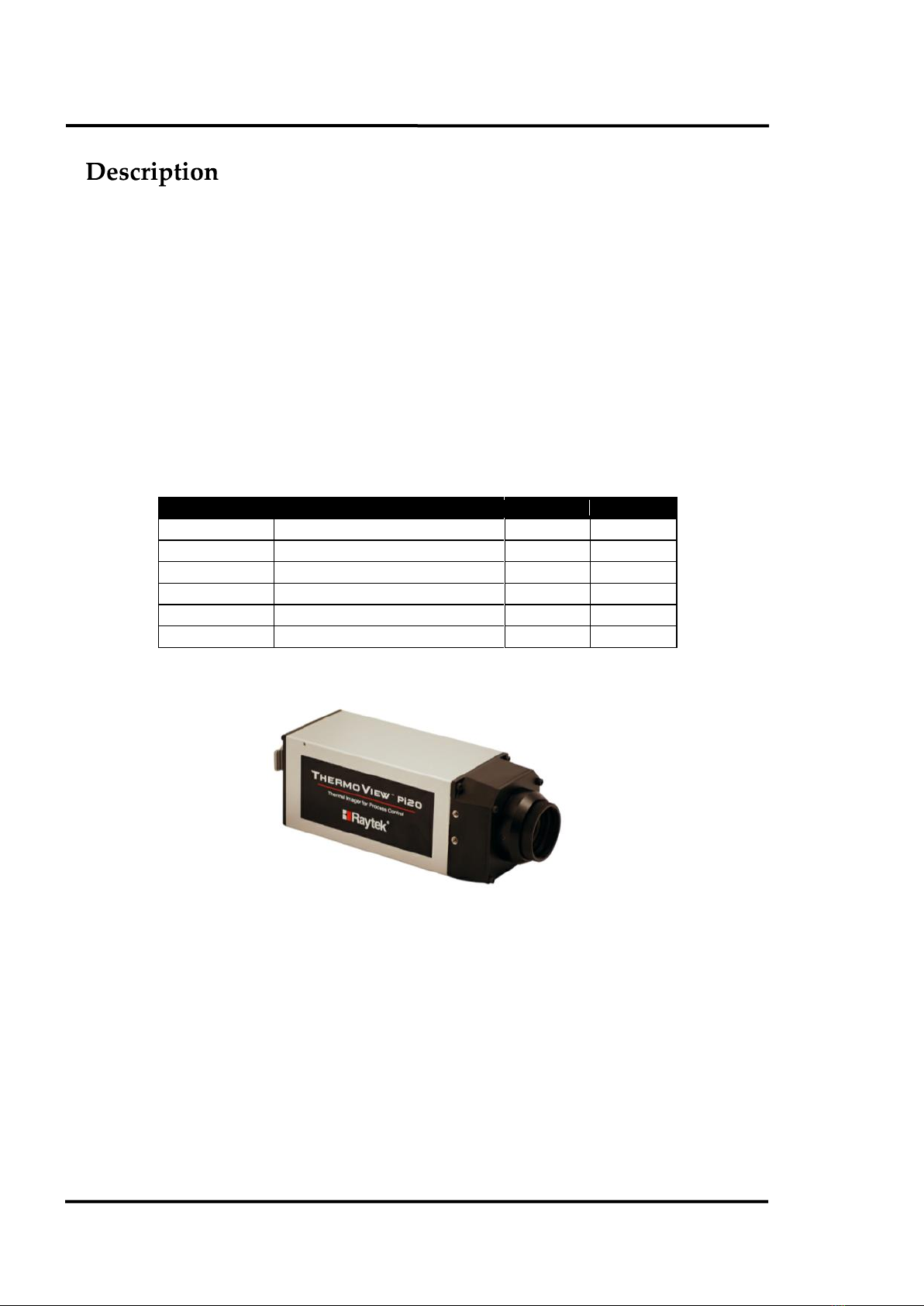
2 DESCRIPTION..................................................................................................................................................8
2.1 SYSTEM ARCHITECTURE ...............................................................................................................................9
3 TECHNICAL DATA.......................................................................................................................................10
3.1 MEASUREMENT SPECIFICATIONS ...............................................................................................................10
3.2 OPTICAL SPECIFICATIONS ..........................................................................................................................11
3.3 ELECTRICAL SPECIFICATIONS.....................................................................................................................13
3.4 GENERAL SPECIFICATIONS .........................................................................................................................13
3.5 DIMENSIONS ...............................................................................................................................................14
3.6 SCOPE OF DELIVERY....................................................................................................................................15
4 BASICS .............................................................................................................................................................16
4.1 MEASUREMENT OF INFRARED TEMPERATURES .........................................................................................16
4.2 EMISSIVITY OF TARGET OBJECT ..................................................................................................................16
5 INSTALLATION ............................................................................................................................................17
5.1 AMBIENT TEMPERATURES ..........................................................................................................................17
5.2 ENVIRONMENT ...........................................................................................................................................17
5.3 ELECTRICAL INTERFERENCE.......................................................................................................................17
5.4 GEOMETRY ..................................................................................................................................................18
5.5 FOCUSING ...................................................................................................................................................19
5.6 MOUNTING .................................................................................................................................................20
5.7 CABLE CONNECTIONS ................................................................................................................................21
5.7.1 Connecting the Ethernet Cable ...........................................................................................................21
5.7.2 Connecting the Power .........................................................................................................................21
5.7.3 Connecting the RS232 Cable...............................................................................................................22
5.7.4 Connecting the Video Cable ................................................................................................................22
5.8 ETHERNET COMMUNICATION....................................................................................................................23
5.8.1 Changing the Ethernet Settings for the PC.........................................................................................23
5.8.2 Changing the Ethernet Settings for the Camera .................................................................................25
5.9 INDUSTRIAL POWER SUPPLY ......................................................................................................................26
6 THERMOVIEW START-UP APPLICATION............................................................................................27
7 ACCESSORIES................................................................................................................................................28
7.1 OVERVIEW...................................................................................................................................................28
7.2 SPARES ........................................................................................................................................................28
7.3 MOUNTING BRACKET.................................................................................................................................29
7.4 COOLING ENCLOSURE ................................................................................................................................30
7.4.1 Technical Data ....................................................................................................................................30
7.4.2 Cooling ................................................................................................................................................31
7.4.3 Air Barrier...........................................................................................................................................31
7.4.4 Installation ..........................................................................................................................................32
7.5 OUTDOOR ENCLOSURE...............................................................................................................................35
7.5.1 Technical Data ....................................................................................................................................35
7.5.2 Installation ..........................................................................................................................................36
7.6 DIGITAL INPUT /RELAY OUTPUT MODULE ...............................................................................................40

7.7 DIGITAL I/O AND ANALOG OUTPUT MODULE......................................................................................... 42
7.7.1 Changing the Output Type ................................................................................................................ 44
7.8 ETHERNET SWITCH..................................................................................................................................... 45
7.9 FIBER OPTIC /RJ45 ETHERNET CONVERTER ............................................................................................. 46
7.10 JUNCTION BOX ......................................................................................................................................... 47
7.11 DATATEMP PI SOFTWARE........................................................................................................................ 48
8 MAINTENANCE............................................................................................................................................ 49
8.1 TROUBLESHOOTING ................................................................................................................................... 49
8.2 CLEANING THE LENS ................................................................................................................................. 49
9 APPENDIX....................................................................................................................................................... 50
9.1 DETERMINATION OF EMISSIVITY................................................................................................................ 50
9.2 TYPICAL EMISSIVITY VALUES..................................................................................................................... 50
9.3 CONFIGURING OF I/O MODULES ............................................................................................................... 54
9.3.1 Overview............................................................................................................................................. 54
9.3.2 Installing the Configuration Software ................................................................................................ 54
9.3.3 IP Address Setting.............................................................................................................................. 54
9.4 DEFINING OF FIREWALL EXCEPTIONS........................................................................................................ 56

Safety Instructions
Pi20 Rev. B 09/2011 7
1
This document contains important information, which should be kept at all times with the instrument
during its operational life. Other users of this instrument should be given these instructions with the
instrument. Updates to this information must be added to the original document. The instrument can
only be operated by trained personnel in accordance with these instructions and local safety
regulations.
Acceptable Operation
This instrument is intended only for temperature measurement and is appropriate for continuous use.
The instrument operates reliably in demanding conditions, such as in high environmental
temperatures, as long as the documented specifications are adhered to. Compliance with the operating
instructions is necessary to ensure the expected results.
Unacceptable Operation
The instrument should not be used for medical diagnosis.
Replacement Parts and Accessories
Use only original parts and accessories approved by the manufacturer. The use of other products can
compromise the operational safety and functionality of the instrument.
Instrument Disposal
Disposal of old instruments should be handled according to professional and
environmental regulations as electronic waste.
Operating Instructions
The following symbols are used to highlight essential safety information in the operation instructions:
Helpful information regarding the optimal use of the instrument.
Warnings concerning operation to avoid instrument damage or personal injury.
Incorrect use of 110 / 230 V electrical systems can result in electrical hazards and personal
injury. All instrument parts supplied with electricity must be covered to prevent physical
contact and other hazards at all times.

Description
8 Rev. B 09/2011 Pi20
2
The ThermoViewTM Pi20 is a rugged thermal imaging camera designed for industrial process control
applications. The camera is designed with an IP54 rating to withstand demanding industrial
environments.
The ThermoView Pi20 provides easy networking over long distances using the standard Ethernet
interface. This interface allows for the PC operating the DTPi software to be located far away. The
Ethernet interface transmits up to 30 frames per second of imaging data and also allows for camera
control. For long Ethernet cable runs beyond 90 m (295 ft), additional fiber optic Ethernet accessories
are available.
The ThermoView Pi20 process imager is a noncontact and highly sensitive infrared thermal camera.
The infrared radiation emitted from measured objects is detected and converted to an electrical signal
by a two-dimensional uncooled focal plane array detector. After this, the amplified analog
temperature signal is converted to a digital signal, which is displayed as a thermal image in color or
black-and-white on a PC running TSA or DataTemp®(DTPi) software.
Part number
Temperature Range
Lens Type
Focus
RAYPi20LTMA
-40 to 500°C (-40 to 932°F)
21.7° x 16°
manual
RAYPi20LTMB
-40 to 500°C (-40 to 932°F)
30° x 22°
manual
RAYPi20HTMA
200 to 2000°C (392 to 3632°F)
21.7° x 16°
manual
RAYPi20HTMB
200 to 2000°C (392 to 3632°F)
30° x 22°
manual
RAYPi20LTRC
-40 to 500°C (-40 to 932°F)
45.2° x 33.7°
remote
RAYPi20HTRC
200 to 2000°C (392 to 3632°F)
45.2° x 33.7°
remote
Table 1: Available Models
Figure 1: ThermoView Pi20 Process Imager

Description
Pi20 Rev. B 09/2011 9
Figure 2: Rear View
2.1 System Architecture
Figure 3: Typical System Architecture for Multi-Camera Usage
Ethernet Switch
(XXXPi20SWH1)
Windows Computer
DTPi Software
Digital I/O Module
(XXXPi206060)
Digital/Analog I/O Module
(XXXPi206024)
Ethernet Communication
optional Fiber Optic
Pi20 Camera
Pi20 Camera
Earth Ground
RS232 Interface
Ethernet Communication
Power Switch
Video Output
Alarm Output
(not supported)
Power Input
LED

Technical Data
10 Rev. B 09/2011 Pi20
3
3.1 Measurement Specifications
Measuring Temperature
Pi20LT, range 1 -40 to 120°C (-40 to 248°F)
Pi20LT, range 2 0 to 500°C (32 to 932°F)
Pi20HT 200 to 2000°C (392 to 3632°F)
Minimum Detectable Temperature Difference (NETD)
1
Pi20LT, range 1 0.08°C at 30°C measuring temperature
Pi20LT, range 2 0.3°C at 30°C measuring temperature
Pi20HT 2°C at 200°C measuring temperature
System Accuracy
2
± 2% of reading or ± 2°C (4°F), whichever is greater
Spectral Response 8 to 14 µm
Detector uncooled focal plane array (micro bolometer)
Number of Pixels
3
320 x 240 (horizontal x vertical)
Thermal Time Constant 16 ms
Repeatability within the accuracy specifications
Ethernet Frame Rate 30 frames / sec
A/D resolution 14 bits
Emissivity Correction 0.10 to 1.00
1
at 30 frames/sec
2
throughout the operating temperature range
3
3 edge lines of screen are out of the specification

Technical Data
Pi20 Rev. B 09/2011 11
3.2 Optical Specifications
The following optical specification is based on the theoretical calculated spot size derived on the pitch
of the camera detector array and the lens focal length. Typically, for accurate temperature
measurements, the target area needs to be 2 to 3 times larger than that determined by the calculated
theoretical spot sizes, which corresponds to 7 x 7 pixels.
21.7° Lens (MA)
Field of View (FOV) 21.7° x 16.4° (horizontal x vertical)
Instant. Field of View (IFOV) 1.2 mrad
Distance to Spot Size Ratio (D:S) 830:1
Focus Range 30 cm to ∞ (12 in to ∞)
Measuring distance
Thermal image (H x V)
Minimum detectable spot size (H x V)
0.3 m (1 ft)
0.11 x 0.09 m (0.36 x 0.29 ft)
0.36 x 0.36 mm (0.014 x 0.014 in)
0.5 m (1.6 ft)
0.19 x 0.14 m (0.62 x 0.46 ft)
0.6 x 0.6 mm (0.023 x 0.023 in)
1.0 m (3.3 ft)
0.38 x 0.29 m (1.25 x 0.95 ft)
1.2 x 1.2 mm (0.047 x 0.047 in)
5.0 m (16 ft)
1.9 x 1.4 m (6.2 x 4.6 ft)
6.0 x 6.0 mm (0.24 x 0.24 in)
10 m (33 ft)
3.8 x 2.9 m (12.5 x 9.5 ft)
12 x 12 mm (0.47 x 0.47 in)
30° Lens (MB)
Field of View (FOV) 30.0° x 22.7° (horizontal x vertical)
Instant. Field of View (IFOV) 1.7 mrad
Distance to Spot Size Ratio (D:S) 596:1
Focus Range 30 cm to ∞ (12 in to ∞)
Measuring distance
Thermal image (H x V)
Minimum detectable spot size (H x V)
0.3 m (1 ft)
0.16 x 0.12 m (0.53 x 0.39 ft)
0.5 x 0.5 mm (0.02 x 0.02 in)
0.5 m (1.6 ft)
0.27 x 0.2 m (0.89 x 0.66 ft)
0.84 x 0.84 mm (0.033 x 0.033 in)
1.0 m (3.3 ft)
0.54 x 0.4 m (1.77 x 1.31 ft)
1.68 x 1.68 mm (0.066 x 0.066 in)
5.0 m (16 ft)
2.7 x 2.0 m (8.8 x 6.5 ft)
8.4 x 8.4 mm (0.33 x 0.33 in)
10 m (33 ft)
5.4 x 4.0 m (17.7 x 13.1 ft)
17 x 17 mm (0.67 x 0.67 in)

Technical Data
12 Rev. B 09/2011 Pi20
45° Lens (RC)
Field of View (FOV) 45.2° x 33.7° (horizontal x vertical)
Instant. Field of View (IFOV) 2.46 mrad
Distance to Spot Size Ratio (D:S) 406:1
Focus Range 30 cm to ∞ (12 in to ∞)
Measuring distance
Thermal image (H x V)
Minimum detectable spot size (H x V)
0.3 m (1 ft)
0.25 x 0.19 m (0.82 x 0.62 ft)
0.79 x 0.79 mm (0.03 x 0.03 in)
0.5 m (1.6 ft)
0.38 x 0.29 m (1.25 x 0.95 ft)
1.2 x 1.2 mm (0.05 x 0.05 in)
1.0 m (3.3 ft)
0.77 x 0.58 m (2.52 x 1.90 ft)
2.4 x 2.4 mm (0.09 x 0.09 in)
5.0 m (16 ft)
3.8 x 2.9 m (12.5 x 9.5 ft)
12 x 12 mm (0.47 x 0.47 in)
10 m (33 ft)
7.7 x 5.8 m (25.2 x 19.0 ft)
24 x 24 mm (0.94 x 0.94 in)
Please note that the lenses are not interchangeable in the field.

Technical Data
Pi20 Rev. B 09/2011 13
3.3 Electrical Specifications
Primary Interface Ethernet (default IP address: 192.168.200.254)
Optional Interface RS232
4
(special accessory cable is required)
Video Output NTSC, composite video (BNC connector)
LED (green) lights at power supply ON.
Power Supply + 11 to 13 VDC (12 VDC nominal)
Power Consumption 8 W (typ), 13 W (max)
3.4 General Specifications
Environment Rating IP54 (IEC60529)
Operating Ambient Temperature -15 to 50°C (5 to 122°F)
Operating Internal Temperature -10 to 65°C (14 to 149°F)
Storage Temperature -40 to 70°C (-40 to 158°F)
Warm-up Time 30 min.
Relative Humidity less 90%, non-condensing,
for operating and non-operating ambient temperature range
Vibration Resistance 29.4 m/sec2(3 G) (IEC60068-2-6)
Shock Resistance 294 m/sec2(30 G) (IEC60068-2-27)
Dimensions (W x H x D) 65 x 65 x 208 mm (2.5 x 2.5 x 8.1 in)
Weight approx. 1 kg (2.2 lb)
4
RS232 is specifically for camera setup in the event the user changes the camera to a different address and then forgets it.

Technical Data
14 Rev. B 09/2011 Pi20
3.5 Dimensions
Figure 4: Camera with Manual Focus (…MA, …MB)
Figure 5: Camera with Remote Focus (…RC)
3 x M4 screw, 5 mm (0.2 in) depth
2 x M4 screw, 5 mm (0.2 in) depth (same on other side)
M2.5 screw, 4 mm (0.16 in) depth
(same on other side)
3 x M4 screw, 5 mm (0.2 in) depth
2 x M4 screw, 5 mm (0.2 in) depth (same on other side)
M2.5 screw, 4 mm (0.16 in) depth (same on other side)

Technical Data
Pi20 Rev. B 09/2011 15
3.6 Scope of Delivery
The delivery package includes the following:
Pi20 ThermoView process imager
Straight Ethernet cable, 7.5 m (25 ft) long
Power supply cable, 7.5 m (25 ft) long
Ethernet Crossover Adapter for direct connection to older PC’s
Industrial DIN rail mounted power supply (XXXPi20PS1)
ThermoView Start-up Software Application (TSA)
Operations manual on CD
Quick Start instructions (hardcopy included in the box)

Basics
16 Rev. B 09/2011 Pi20
4
4.1 Measurement of Infrared Temperatures
Every object emits an amount of infrared radiation (IR) according to its surface temperature. The
intensity of the infrared radiation changes with the temperature of the object. Depending on the
material and surface properties, the emitted radiation lies in a wavelength spectrum of approximately
1 to 20 µm. The intensity of the infrared radiation (”heat radiation”) is dependent on the material. For
many substances, this material-dependent constant is known. It is referred to as ”emissivity value”.
See appendix 9.2 Typical Emissivity Values on page 50.
Infrared thermometers are optical-electronic sensors. These sensors are able to detect ”radiation of
heat”. Infrared thermometers consist of a lens, spectral filter, sensor, and an electronic signal
processing unit. The task of the spectral filter is to select the wavelength spectrum of interest. The
sensor converts the infrared radiation into an electrical signal. The connected electronics process this
signal for further analysis. The intensity of the emitted infrared radiation is thereby used to determine
the temperature of the target. Since the intensity of the infrared radiation is dependent on the material,
the appropriate emissivity can be selected on the sensor.
The biggest advantage of the infrared thermometer is its ability to measure temperature without the
need to be in contact with the target. Consequently, surface temperatures of moving or hard to reach
objects can be easily measured.
4.2 Emissivity of Target Object
For accurate temperature readings, the sensor must be set to the appropriate emissivity value for the
target material. Determine the emissivity of the target object, as described in appendix 9.1
Determination of Emissivity on page 50.
When measuring materials with low emissivity, the results could be effected by interfering infrared
radiation from background objects (such as heating systems, flames, fireclay bricks, etc. near to or
behind the target object). This type of problem can occur when measuring reflective surfaces and very
thin materials, such as plastic films and glass. This error can be reduced to a minimum if particular
care is taken during installation, and the camera is shielded from reflected infrared radiation.

Installation
Pi20 Rev. B 09/2011 17
5
5.1 Ambient Temperatures
Without water cooling, the camera is designed for ambient operating temperatures between -15 to
50°C (5 to 122°F). With water cooling equipment, it can be used in environments at higher
temperatures. For more details, see section 7.4 Cooling Enclosure, page 30.
5.2 Environment
This unit complies with the international protection standard IP54. "Splash-proof" here refers to
"effective against splashing by water from every direction."
Note that effectiveness against splashing is possible only with terminal caps in place and the power
connector connected. To maintain IP54 compliance, we recommend periodic inspection/replacement
of gaskets. Gaskets should be replaced every two years.
5.3 Electrical Interference
To minimize electrical or electromagnetic interference, follow these precautions:
Mount the unit as far away as possible from possible sources of interference such as
motorized equipment producing large step load changes!
Ensure a fully insulated installation of the unit (avoid ground loops!).
Make sure the shield wire in the unit cable is earth grounded at one location!
To avoid potential differences, use a single power circuit to power both the camera and the PC
running the software!

Installation
18 Rev. B 09/2011 Pi20
5.4 Geometry
The camera provides different lens models (factory installed) to accommodate a wide range of
applications. Each individual lens provides different thermal images (Field of View) and minimum
detectable spot sizes (Instantaneous Field of View). The optical diagram below shows the principal
graphical representation for measuring distance over the field of view.
Figure 6: Field of View for the Camera
It is important that the camera is mounted at a distance from the target sufficient to be able to “see”
the entire area of interest. For this reason, the manufacturer provides a software tool (on the support
CD or downloadable from the website) calculating the Field of View for a given lens based on a
specific camera mounting distance.
Minimum detectable spot size
(Instantaneous Field of View)
Thermal Image
(Field of View)
()

Installation
Pi20 Rev. B 09/2011 19
Figure 7: Field of View Calculator
5.5 Focusing
After the camera has been mounted, it is important to make sure that the optimum focus has been
established for the given mounting distance. It is important to focus the camera correctly to obtain the
sharpest image of the target you wish to view.
The camera with remote focus (…RC) can be set via the TSA software.
The camera with manual focus (…MA, …MB) can only be focused manually on the front of the
camera.
Figure 8: Focusing the Camera with Manual Focus (…MA, …MB)
It should be noted that if the focus changes or the camera is moved from its installed location, the user
must make sure that a new focus setting has been achieved.
Clockwise turning:
focal point goes far
Counter-clockwise turning:
focal point comes near

Installation
20 Rev. B 09/2011 Pi20
5.6 Mounting
The camera installation requires the most planning effort. The camera needs to be accurately mounted
in relationship to the product (target). Adjustments to align the camera with the target may have to be
designed into the camera mounting to provide the required alignment accuracy. Avoiding or
removing physical mounting limitations and obstructions in the camera’s optical path, may also be
required.
For dedicated mounting equipment, see section 7.3 Mounting Bracket, page 29.
This manual suits for next models
6
Table of contents
Popular Laboratory Equipment manuals by other brands

Extron electronics
Extron electronics PI 130 installation guide

Tenma
Tenma ST-980 user manual

Liquid Instruments
Liquid Instruments Moku:Pro quick start guide

Agilent Technologies
Agilent Technologies Magnis NGS Prep System user guide

PI
PI L-505.013212 user manual

Selecta
Selecta AUTESTER ST DRY PV B 12L manual