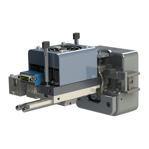
Sonation DBO-TF-FIS User manual

Sonation
lab solutions.
lab solutions.
Sonation
DOUBLE BARREL OVEN DBO-TF-FIS
Operators Manual
Analycs

Seite 2
CE-Konformitätserklärung
CE Declaration of Conformity
CE Déclaration de Conformité
CE Dichiarazione di Conformità
Der Hersteller /The manufacturer / Le fabricant / Il fabbricante
Sonation GmbH
Alte Schulstr. 39 –88400 Biberach - Deutschland
erklärt hiermit, dass die Produkte
herewith declares that the products
déclare par la présente que le produits
dichiara che il prodotti
DBO-TF-FIS
den Anforderungen der folgenden EG-Richtlinien entspricht.
meets the provisions of following EC-Directives.
remplit les exigences des Directives CE suivantes.
soddisfa tutte le disposizioni dalle Direttive CE.
Richtlinie
Directive
Directive
Direttiva
gültig bis
valid until
valable jusqu’à
con validità fino al
gültig ab
valid after
valable à partir de
applicabile dal
2006/95/EG, EC, CE
19.04.2016
2014/35/EU
20.04.2016
2004/108/EG, EC, CE
19.04.2016
2014/30/EU
20.04.2016
2011/65/EU
03.01.2013
Angewandte Normen:
Applied standards:
Normes appliquées:
Norme applicate :
EN 61326-1:2013 - Basic requirements
EN 61010-1 :2010 + Cor. :2011
Diese Erklärung gilt für die oben genannten Produkte ab dem Unterzeichnungsdatum.
This declaration is valid for the above mentioned products after the signature date below.
La présente déclaration est valable à partir de la date de signature.
Questa dichiarazione vale per il suddetto prodotti dalla data di firma.
______________________ __________________________
Ort / place / lieu / luogo Unterschrift / signature / signature / firma
Datum /date / date / data
Name / name / nom / nome:
(Geschäftsführer / management / directeur / delegato)
Biberach 04. Dec. 2020
Christof Völkle

Seite 3
Contents
1 Safety 4
1.1 Importantsafetyinstrucons .................................................................................................................................... 4
1.2 Intended use.............................................................................................................................................................. 4
1.3 Non-intended use...................................................................................................................................................... 4
1.4 Examples of foreseeable misuse ............................................................................................................................... 4
1.5 Who may use and operate the column oven ............................................................................................................ 5
1.6 Safety signs and symbols........................................................................................................................................... 5
Safety symbols on the device and in the user manual........................................................................................... 5
Symbols on the nameplate .................................................................................................................................... 5
2 Productdescripon 6
2.1 Overview ................................................................................................................................................................... 6
Column Oven (upper and lower part) ................................................................................................................... 6
Regulator................................................................................................................................................................ 6
HV-Switch............................................................................................................................................................... 6
2.2 Scope of delivery ....................................................................................................................................................... 7
Double Barrel Oven DBO-TF-FIS............................................................................................................................. 7
2.3 Available accessories................................................................................................................................................. 7
MounngKitforThermoFisherFlexIonSourceES071......................................................................................... 7
MounngKitforThermoFisherFlexIonSourceES072......................................................................................... 7
Micro-Tee with HV-connector ................................................................................................................................ 7
HV-cable with 2mm connector............................................................................................................................... 7
2.4 Hardware................................................................................................................................................................... 8
InstallaonoftheES071mounngkit................................................................................................................... 8
InstallaonoftheES072mounngkit................................................................................................................... 8
InstallaonoftheHV-switch .................................................................................................................................. 9
Aachingtheoventothesource........................................................................................................................... 9
Connecngthecables............................................................................................................................................ 9
2.5 Soware .................................................................................................................................................................. 10
Installing CO-Control ............................................................................................................................................ 10
3 Usage 10
3.1 ColumnloadingandapplyingtheHVvialiquidjuncon......................................................................................... 10
3.2 Using CO-Control ..................................................................................................................................................... 11
4 Maintenance and Care 12
Maintenance ........................................................................................................................................................ 12
Cleaning ............................................................................................................................................................... 12
5 Final Disposal 12
6 Technicaldata 12
7 FAQ-FrequentlyAskedQuesons 13

Page 4
Column Oven DBO-TF-FIS User manual
1 Safety
1.1 Importantsafetyinstrucons
Pleasereadtheseoperanginstruconscarefullybeforeusingtheproduct.ItcontainsimportantnotesonInstalla-
onandusage.
Theusermanualispartoftheproduct.Keepitinasafeplace.Iftheproductissold,rentedorpassedoninanyother
way,theusermanualmustbeincluded.
Heedallwarnings.Thesepointoutdangersandgiverecommendaonsforaccidentprevenon.
Onlyinstalltheunitinlocaonsexpresslyrecommendedbythemanufacturer.
Ifcondensaonformsaerunpacking,allowatleast2hoursfortheunittoacclimaze.
Thisdevicemayonlybeoperatedatsocketswithprotecveearth.
Makesurethatyoucannottripoverthemainscableandthatthecableisnotdisconnected,ispinched,tornoor
squeezed.
Only use accessories expressly recommended by the manufacturer.
Leaveallmaintenanceworktoanexperiencedservicetechnician.Servicingorrepairsarerequiredifthereisvisible
damage,ifthepowercordorplugisdamaged,ifliquidhasbeenspilledinsidetheapparatus,iftheapparatushas
beenexposedtorain,ifitdoesnotperformasexpected,orifithasfallen.
Onlyuseconneconcablesorextensioncablesthatareapprovedforthemaximumpermissibletotalcurrentor
power.
Operaonofthedeviceinamannernotintendedbythemanufacturermayaecttheproteconprovidedbythe
device.
1.2 Intended use
Theovenisexclusivelydesignedfortheheangandtemperingofseparaoncolumnsinnano-ESIapplicaons.
TheovenisaproductaccordingtotheMachineryDirecve2006/42/EC(completemachine).
The oven must be installed as described in this manual.
Thefanmustbeabletoturnfreeandmaynotbeblocked.
Do not use any adhesive tape or other non-heat-resistant materials inside the oven.
Theovenisconstructedastechnicalworkequipmentandnotintendedforprivateuse.
The device may only be used in clean and dry rooms.
Thelimitvaluesfortemperatureandhumidityduringtransport,storageandoperaonspeciedunder6„Technical
data“ on page 12 must not be exceeded or undercut.
Theovenmustnotbeusedinpotenallyexplosiveatmospheres,especiallyinareasenrichedwithoxygen,combus-
bleanesthecs(classAP)orcombusbleanesthecswithoxidizingagents(classAPG).
Theovenmustbekeptawayfromeasilyinammableandcombusbleliquids.
Ifaliquidshouldpenetratetheelectricalpartoftheovenorregulatoritistobesetimmediatelyoutofoperaonand
mustbecheckedbyaspecialist.
Usetheovenonlywithinthespecicaonsspeciedinthismanual.
Thevalidaccidentguardingregulaonsaccordingtoeachcountrymustbeconsidered.
The device may only be repaired by a specialist.
1.3 Non-intended use
A non-intended use is given when the equipment is treated in any way that is contrary to any of the points from the
chapter1.2„Intendeduse“onpage4.
Iftheovenisnotusedasintended,handledimproperlyandused,assembledorhandledbyuntrainedpersonnel,
hazardsmayariseforpersonnelfromtheoven.
1.4 Examples of foreseeable misuse
Use in environments with high humidity > dew point.
UseinroomswithexplosiveatmospheresaccordingtoATEXdirecve.

User manual Column Oven DBO-TF-FIS
Page 5
Use with damaged supply lines.
Outdoor use.
1.5 Whomayuseandoperatethecolumnoven
Physicallyandmentallyhealthypersonswhohavefullyreadandunderstoodtheinstruconsforusemayuseand
operatethecolumnovenaslongastheyarenotaectedbymedicaonordrugs.
1.6Safety signs and symbols
Safetysymbolsonthedeviceandintheusermanual
The“generalmandatorysign”indicatesthatyoushouldbehaveaenvely.Markedinformaoninthis
usermanualisintendedtodrawyourparcularaenon.Youwillreceiveimportantinformaonon
funcons,sengsandprocedures.Failuretodosomayresultinmalfunconoftheequipmentorits
surroundings.
The“generalwarningsign”indicatesdangerpointsorpossibledangeroussituaons.Markedinfor-
maoninthisusermanualappliestoyourspecialaenon.Youwillreceiveimportantinformaon
onsafety-relevantmaers.Failuretodosomayresultinpersonalinjury,malfunconofthedevice
ortheenvironment.
Thewarningsign“Hotsurface”indicatesapotenallyhotsurface.Non-observancemaycauseburns.
Itisessenalthatyouobservethesafetyinstruconsintheoperanginstrucons.
Thewarningsign“Warningofelectricalvoltage”indicatespotenalhazardsduetoelectricalvolt-
age.Theposionsonthedevicemarkedwiththissymbolandtheinformaonintheseoperang
instruconsareintendedtodrawyourparcularaenon.Youwillreceiveimportantinformaon
onsafety-relevantmaers.Failuretodosomayresultinpersonalinjury,malfunconofthedevice
orthesurroundingarea.
Symbolsonthenameplate
ConformitytolowvoltageandEMCdirecves
Donotdisposeofinhouseholdwaste
Indoor use only
Appliance class I

Page 6
Column Oven DBO-TF-FIS User manual
2 Productdescripon
2.1 Overview
ThedoublebarrelovenDBO-TF-FISallowstheparallelusageoftwoindependantanalycalcolumns.Asloading,equil-
ibraonandwashingstepscanbealternated,theulizaonandthroughputofthemassspectrometercanbesigni-
cantly increased.
ColumnOven(upperandlowerpart)
❶❶Lockingbars ❷❷Receptacle for oven control cable ❸❸Cross/T-holdersonslidingrails
❹❹Column clamp handles ❺❺Mounngbar ❻❻Lateral sliding rail
Regulator
❶❶“Oven control” connector ❷❷High voltage switch input ❸❸High voltage switch output
❹❹“RS232/Contactclosure”connector ❺❺Power in connector
HV-Switch
❶❶High voltage input from Flex Ion source
❷❷High voltage output to column 1
❸❸High voltage output to column 2
❹❹Mounngplatewithscrewsandsleves
❺❺Controlinput(boomside,notvisibleonillustraon)
❶❶
❷❷
❸❸
❹❹
❺❺
❻❻
Fig. 1: Column oven (top and boom part)
❶❶
❷❷❸❸
❹❹
❺❺
Fig. 2: Regulator - front and back view
❶❶
❷❷
❸❸
❹❹
❺❺
Fig. 3: HV-Switch with screws and sleves

User manual Column Oven DBO-TF-FIS
Page 7
2.2 Scopeofdelivery
DoubleBarrelOvenDBO-TF-FIS
1xColumnoven(topandboompartwith4columnpins)
1 x Regulator
1xHV-switchwith2xM4x40mounngscrewsand2x24mmplascsleeves
1 x HV-cable: Source to HV-switch
1 x Oven control cable: Regulator to oven
1 x HV control cable: Regulator to HV-switch
1 x Data cable for RS232 and contact closure
1 x USB to serial adapter
1x24Vpowersupplywithwiderangeinputandpowercable(withEU,CH,UKorUSplug)
2xCrossholderwithcrossholderlid,2xM4x6screwand1xnylonthumbscrewM4x16each
1xCountersunkheadscrewM5x20withM5lockingnutformounngtheoventothesource
1xUSBashdrivewithsoware
1 x This manual
2.3 Availableaccessories
MounngKitforThermoFisherFlexIonSourceES071
AllowstheoventobemountedonaThermoFisherFlexIonSourceES071.Consistsof:
1 x Acrylic shield
1xModieduppercameraholder
1xDistanceblockforlecameraholder
2xScrewM5x20Allenhead
Ordercode:PRSO-V2-KES71
MounngKitforThermoFisherFlexIonSourceES072
AllowstheoventobemountedonaThermoFisherFlexIonSourceES072.Consistsof:
1 x Acrylic shield
1 x Upper camera holder
1xLecameraholder
1 x Oven holder
1 x Acrylic shield holder
Ordercode:PRSO-V2-KES72
Micro-TeewithHV-connector
MicroT-piecewith3x360µmconnectorsand2mmHVconnectorforsprayvoltagefeed(liquidjuncon).
Order code: PRSO-V2-MT
HV-cablewith2mmconnector
ConneconcablebetweentheHVoutputoftheFlexIonSourcerespecvelytheHVoutputoftheHV
switch and a 2mm plug.
Order code: PRSO-HV-LE-HI

Page 8
Column Oven DBO-TF-FIS User manual
Installaon
2.4 Hardware
Beforeinstallingtheovenmakesurethehighvoltage(sprayvoltage)hasbeenturnedo.
TheovencanbeusedwiththeES071andtheES072versionoftheThermoFisherFlexIonSource.Tobeabletousethe
ovenattherespecvesource,thecorrespondingmounngkitisrequired(see„2.3Availableaccessories“).
InstallaonoftheES071mounngkit
Firsttheoriginalacrylicsafetyshieldhastoberemoved.Aer
removing the two screws on the shield clamp it can be dis-
mounted.
Also the two camera holders have to be dismounted by remov-
ing the corresponding screws. The upper camera holder has
tobereplacedbytheoneintheconversionkit.Pleaseusethe
originalscrewstoxthemodiedcameraholder.
Thedistanceblockhastobemountedbetweenthelecamera
holderandthesource.Toxthelecameraholderpleaseuse
theprovidedM5x20screwsastheoriginalscrewsaretooshort.
Now mount the provided safety shield instead of the original
one. Please see Fig. 4 for reference.
InstallaonoftheES072mounngkit
Removetheshieldclamp,theupperandlecameraholder,theacrylicshield,theXYZ-manipulatorandtheaached
mounngbarbylooseningthescrewsmarkedinFig.5.
Slidethemodiedacrylicshieldfromtheconversionkitontothesource.Youmighthavetobenditcarefullytomake
itslipovertheange.
InstalltheovenholderontotheXYZ-manipulator.
ReinstalltheXYZ-manipulatorontothesourcebypungtheshieldholderbetweenthemanipulatorandthemanipu-
lator holder using the original screws.
Installthemodiedleanduppercameraholdersbyreusingtheoriginalscrews.
Fig. 4: Installaon of the ES071 mounng kit
Lecamera holder
Acrylic shield
Mounng bar
XYZ-Manipulator
Shield clamp
Upper camera holder
Modied le
camera holder Modied acrylic shield
Shield holder
Oven holder
Modied upper
camera holder
Fig. 5: Installaon of the ES072 mounng kit
Fig. 6: Mounng the HV-switch to the source Fig. 7: Aaching the oven to the source

User manual Column Oven DBO-TF-FIS
Page 9
Installaon
2.4 Hardware
Beforeinstallingtheovenmakesurethehighvoltage(sprayvoltage)hasbeenturnedo.
TheovencanbeusedwiththeES071andtheES072versionoftheThermoFisherFlexIonSource.Tobeabletousethe
ovenattherespecvesource,thecorrespondingmounngkitisrequired(see„2.3Availableaccessories“).
InstallaonoftheES071mounngkit
Firsttheoriginalacrylicsafetyshieldhastoberemoved.Aer
removing the two screws on the shield clamp it can be dis-
mounted.
Also the two camera holders have to be dismounted by remov-
ing the corresponding screws. The upper camera holder has
tobereplacedbytheoneintheconversionkit.Pleaseusethe
originalscrewstoxthemodiedcameraholder.
Thedistanceblockhastobemountedbetweenthelecamera
holderandthesource.Toxthelecameraholderpleaseuse
theprovidedM5x20screwsastheoriginalscrewsaretooshort.
Now mount the provided safety shield instead of the original
one. Please see Fig. 4 for reference.
InstallaonoftheES072mounngkit
Removetheshieldclamp,theupperandlecameraholder,theacrylicshield,theXYZ-manipulatorandtheaached
mounngbarbylooseningthescrewsmarkedinFig.5.
Slidethemodiedacrylicshieldfromtheconversionkitontothesource.Youmighthavetobenditcarefullytomake
itslipovertheange.
InstalltheovenholderontotheXYZ-manipulator.
ReinstalltheXYZ-manipulatorontothesourcebypungtheshieldholderbetweenthemanipulatorandthemanipu-
lator holder using the original screws.
Installthemodiedleanduppercameraholdersbyreusingtheoriginalscrews.
Fig. 4: Installaon of the ES071 mounng kit
Lecamera holder
Acrylic shield
Mounng bar
XYZ-Manipulator
Shield clamp
Upper camera holder
Modied le
camera holder Modied acrylic shield
Shield holder
Oven holder
Modied upper
camera holder
Fig. 5: Installaon of the ES072 mounng kit
Fig. 6: Mounng the HV-switch to the source Fig. 7: Aaching the oven to the source
InstallaonoftheHV-switch
TheHVswitchhastobeaachedtothesourceasshownonFig.6.Todoso,rstremovetheoriginalscrewsfromthe
boomofthesource,theninserttheslevesandmounttheHV-switchwiththeprovidedscrews.
Aachingtheoventothesource
PlacethemounngbaroftheovenontotheXYZ-manipulatorandxitwiththeprovidedscrewandnutasshownon
Fig.7.IftheXYZ-manipulatorwon’tstayinplace,thisisduetotheweightoftheoven.Thefriconofthemanipulator
canberegulatedwithadjusngscrews.Sojustincreasethefriconunltheovenstaysinposion.
Connecngthecables
Connect the regulator with the provided data cable to an available com-port on your instrument PC. If there is no
com-portavailable,pleaseusetheprovidedUSBtoserialadapter.
The remaining two open leads of this cable can be connected to the “contact closure out” of your instrument to
switchbetweentwopresettemperatures.Thisisonlyneededifyouwanttoswitchautomacallybetweentwopre-
settemperatures.Switchingcanalsobedonewiththeprovidedovencontrolsoware.
Connect the oven to the controller with the provided oven control cable.
Connect the HV cable from the HV output of your Flex Ion Source to “HV IN” on the HV switch.
MS
Regulator
Power supply
24V/200W
HPLC
PC
HV-switch
Flex Ion
Source
Oven
HV-OUT1
HV-IN
HV-OUT2
To column 1
To column 2
Fig. 8: Wiring scheme

Page10
Column Oven DBO-TF-FIS User manual
Connectthetwohighvoltagecables(2xSonaonP/NPRSO-HV-LE-HI)tothe“COL1OUT”and“COL2OUT”oftheHV
switch. The other ends are connected later to the columns using the micro T-pieces with HV connector. If you use the
Thermoliquidjunconkit(P/NES269)theHVcablesarealreadyinstalledtothealsoincludedcrosspieces.Inthis
caseconnectthemlaterasdiscribedin3.1„ColumnloadingandapplyingtheHVvialiquidjuncon“onpage10.
Connectthecontactclosurecable(ThermoP/N6000.1004)betweentheHPLCandthe“CCHV”inputontheregula-
tor.PleaseseeThermoFishertechnote73671fordetailedinformaon.
Connect the 24-Volt power supply to the power connector on the regulator. Thewidesideoftheplugfacesthetop
ofthecontrolmodule,donotforceitintwisted. The power supply will be connected to a wall outlet later.
2.5 Soware
Installing CO-Control
Toinstalltheovencontrolsoware,executesetup.exeinthedirectoryCOControlontheprovidedUSBashdrive.Fol-
lowthestepsofthesetupwizard.ThesowareneedsaninstalledMicroso.NET.Ifthesowarewon‘tstartandthrows
anerrormessageshowing.NETismissing,installitfromtheprovidedUSBashdrive.
3 Usage
3.1 ColumnloadingandapplyingtheHVvialiquidjuncon
Makesurethatthehighvoltage(sprayvoltage)isswitchedoduringtheinstallaonofthecolumns
andduringanysubsequentpluggingorunpluggingofhighvoltagecables.
Makesurethatyouhaveinstalledthecrossholderlidsbeforeswitchingonthehighvoltage.
Donotuseanyadhesivetapeorothertemperaturesensivematerialsinsidetheoven.
Thepoftheemierisverysensive.Becarefulnottohitanythingwheninserngthecolumns.
Duringoperaonthesurfaceoftheovencangetveryhot!
Opentheovenbyturningthelockingbarsatthefront
andbackoftheoven.Thetoppartcannowberemoved.
Remove the cross holders from the sliding rails by loos-
ening the thumb screws.
Removethescrewsontopofthecrossholdersandtake
othecovers.Usea2.5mmAllenscrewdriver.
Connect the columns to the T-pieces with the high
voltageconnectors(SonaonP/NPRSO-V2-MT)ortothe
crosspiecesincludedintheThermoliquidjunconkit
(P/NES269).Useaconnectornexttothehighvoltage
plug and not the one opposite.
Insert the T- or cross pieces into the provided cross hold-
ers and remount the lids.
Connect the high voltage cables coming from “COL1
OUT”and“COL2OUT”fromtheHVswitchtotheT-pieces.IfyouusetheThermoliquidjunconkit(P/NES269)
connect the plugs of the high voltage cables connected to the cross pieces to “COL1 OUT” and “COL2 OUT” at the HV
switch.
Fig. 9: Column loading

User manual Column Oven DBO-TF-FIS
Page 11
Slidethecrossholdersontotheslidingrailswiththecolumnsfacingtheinletsoftheoven.Inmostcasesitworks
besttousethelateralandoneofthefrontalrails.Whenusingthetwofrontalmounngrails,makesurethatthe
high-voltageconnectorspointoutwards,otherwisethereisnotenoughspacetoconnectthehigh-voltagecables.
Now place the columns inside the oven. Longer columns can be wound around the column pins as needed. Therefor
thecolumnpinscanbeplacedinanyofthedesignatedposions.
Theendofeachcolumnisledoutatoneoutleteachandheldinposionbytheclampingmechanism.Placethe
columnsinawaythatthepsareabout5mmapart.
Now reinstall the top part of the oven and plug in the power cord from the power supply to a wall outlet.
The oven is now ready to use.
3.2 Using CO-Control
Aerstarngthesowareitcomesupwiththemainview(Fig.10).
Onthe“COMPorts”tabchoosetheportthecontrollerisconnectedtoandclick„connect“.Nowyoushouldseethe
currenttemperatureoftheoveninthedisplayintheupperright.Ifnotemperatureisdisplayed,pleaseensurethatthe
toppartoftheovensitsproperontheboompart.Iftheovenisnotproperlyclosed,thetemperaturereadoutwill
show -999°C.
Inthemainviewyoucanadjustthetwotemperaturesetpoints„Temp.normal“and„Temp.high“.Byclicking„Switch
regulatoron“theregulatorstartstoheatorcooltheoventooneofthesesetpoints,dependingonthestateofthe
contactclosureinput.Tovisualizethetemperatureprole,agraphwindowcanbedisplayed.Toshowitup,chose
„Opons>ShowGraph“fromthemainmenu.Inthesengswindowunder„Opons>Sengs“thegraphwindowcan
beshownautomacallyonstartup.
Itispossibletounlockanextendedtemperaturerange.Ifyourapplicaonrequireshigherorlowertemperatures,
pleaseaskSonaonforanoponcode.ButalsokeepinmindthatahighertemperaturerangeisstressforthePel-
er-modulesandcanleadtoashorterlifeme.
Fig. 10: Oven control soware co-control

Page 12
Column Oven DBO-TF-FIS User manual
4 Maintenance and Care
Maintenance
Theproductisbasicallymaintenance-freebutnotwear-free.Ifawear-relateddefectshouldoccur,pleasecontactyour
dealerorSonaondirectlytoclarifythefurthersteps.
Cleaning
Useaso,dampclothtocleanthesurfaces.Aggressivesolvents,basesoracidsmustnotbeusedforcleaning.
5 Final Disposal
Disposetheproductinaccordancewithlocalandnaonalsafetyandenvironmentalregulaons.
Theproductcontainselectroniccomponents,cables,metals,plascs,etc.andhastobedisposedinaccordancewith
applicableenvironmentalregulaonsoftherespecvecountry.ThedisposaloftheproductinGermanyissubjecttothe
Elektro-G(RoHS)andintheEuropeanareaoftheEUDirecve2002/95/ECortherespecvenaonallegislaon.
Theproductcanalsobereturnedtothesellerfordisposal.Inthiscasethecostoftransport,includingthepackaging
costsshallbebornebythebuyer.Pleasenofythesellerofthereturnwithin14daysbeforetheexpectedarrival.
6 Technicaldata
Temperature control range
Standard range:
Extended range:
15°C-60°C(59°F-140°F)
15°C-80°C(59°F-176°F)
Temperature control rate
Heang:
Cooling:
30°Cto50°C:Lessthan90s
50°Cto30°C:Lessthan180s
Control accuracy ±0,1°C
Usable column lengts From130mm
Usable column diameter Up to 2mm
Oven weight 0,9kg
Permissibleambientcondions
Transport
Storage
Operaon
Temperature Humidity
-20-60°C/-4-140°F 5-90%(non-condensing)
10-40°C/50-104°F 10-80%(non-condensing)
10-30°C/50-86°F 20-80%(non-condensing)
Power cable
EU
CH
UK
US
CEE7/4plug(Schukoplug)toIEC60320C13,length:1,8m
T12plug(accordingtoSEV1011:2009)toIEC60320C13,length:1,8m
TypeGplug(BS1363)toIEC60320C13,length:1,8m
NEMA-5plugtoIEC60320C13,length:1,8m
Supply voltage 100-240VAC/50-60Hz
Max power input 200W
Appliance class Class I (earth conductor)

User manual Column Oven DBO-TF-FIS
Page 13
7 FAQ-FrequentlyAskedQuesons
MyPCdoesnothaveanyCOMports/noavailableCOMports.CanIruntheovenanyhow?
Yes.PleaseusetheprovidedUSBtoserialconvertertoinstallavirtualcom-port.
I‘vesuccessfullyconnectedtotheovenbutcansllseenotemperature.Whatiswrong?
Pleaseensurethatyourovenisclosedproperly.Whentheovenisopenorevennotproperlyclosed,thetemperature
sensor cannot be read.
Isitpossibletosetuphighertemperaturesthan60°Corlowertemperaturesthan15°C?
Yes,itispossible.PleaseaskSonaonforanoponcode,butrememberthatthelifemeofthePeler-elementswillbe
loweredbecauseoftheaddionalthermalstress.
Thetemperatureoftheovenuctuates/oscillatessomedegreesaroundthesetpoint.What’swrong?
Themostcommoncauseisthattheupperpartoftheovensitsnotproperlyonthelowerpart,sothethermalconnec-
onisbad.Pleasecheckifthecolumnorotherthingsaretrappedbetweentheupperandlowerpart.

Seite 14
Säulenofen DBO-TF-FIS Originalbetriebsanleitung
Thispageisintenonallyleblank

Originalbetriebsanleitung Säulenofen DBO-TF-FIS
Seite 15
Thispageisintenonallyleblank

Sonation
lab solutions.
lab solutions.
Sonation Tel.:+49(0)735130038-39
E-Mail:mail@sonaon.com
www.sonaon.com
SonaonGmbH
Alte Schulstraße 39
D-88400Biberach
IMPROVEYOURSCIENCE
www.sonaon.com Rev.300029_000_00
07.Dec.2020
Table of contents
Other Sonation Laboratory Equipment manuals
Popular Laboratory Equipment manuals by other brands

RS PRO
RS PRO RS-983 instruction manual

Agilent Technologies
Agilent Technologies 7673 operating manual

BANDELIN
BANDELIN SONOREX TECHNIK W 65 Instructions for use
Thermo Scientific
Thermo Scientific Applied Biosystems VeritiPro quick reference

Sheldon
Sheldon VWR International 2015 Installation and operation manual

Agilent Technologies
Agilent Technologies 1200 Infinity Series user guide
