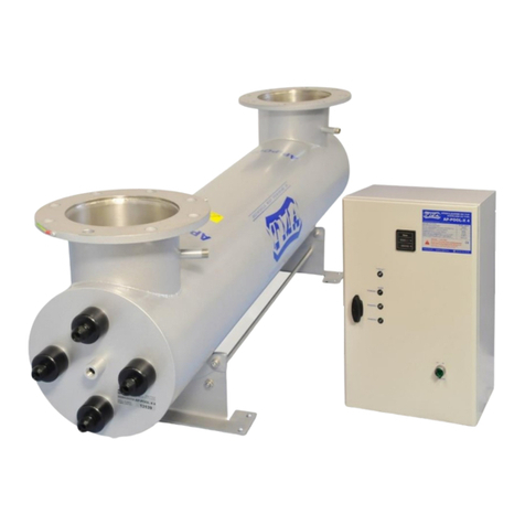
TMA V20 User manual

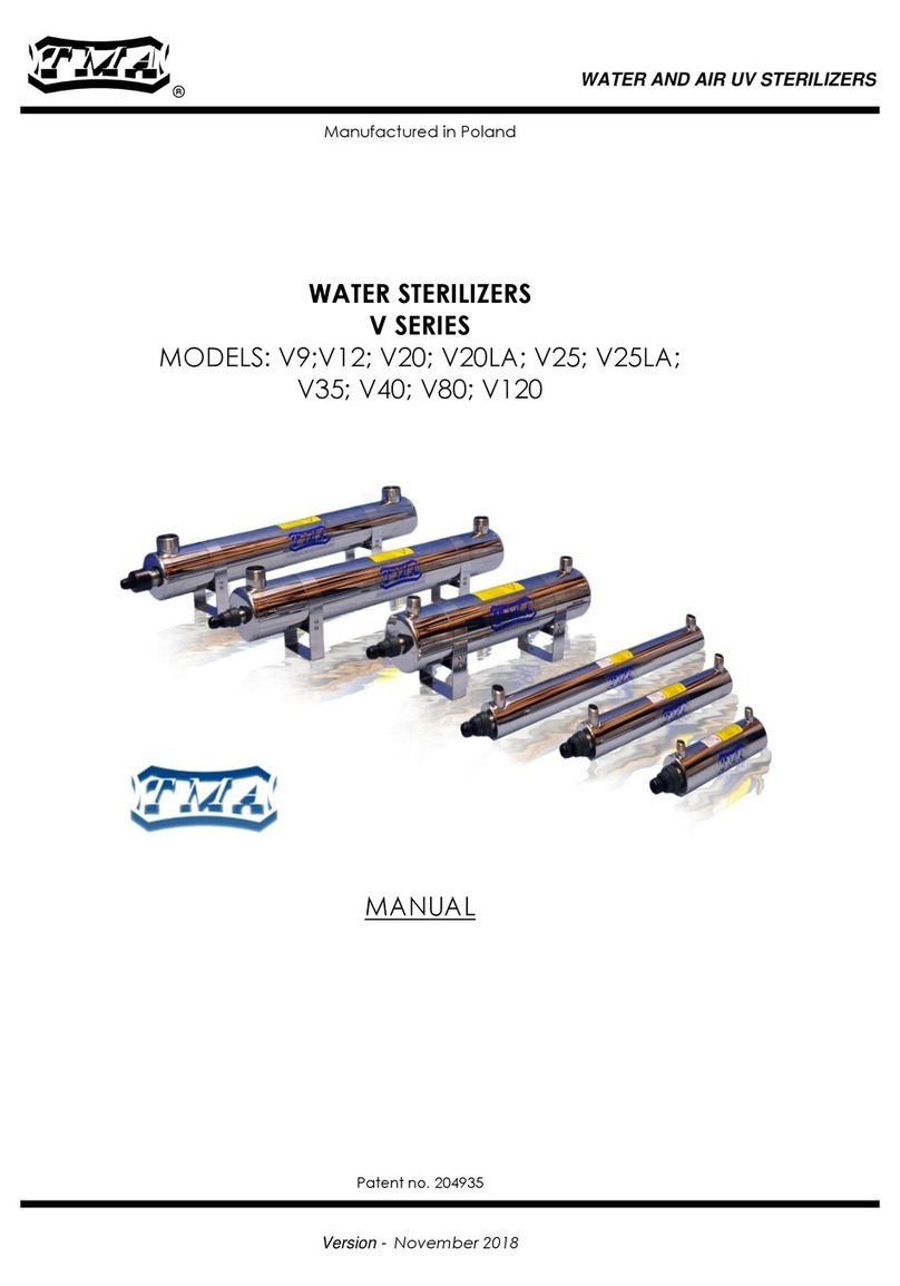
WATERSTERILIZERS
MODELS: V20;V20LA;V40;V80;V120
MANUAL
Patent nr204935
-2012 -
WATERAND AIRUV STERILIZERS

TMA
V20-V120
2
TMA|Bia ostoczek26,gm.Zab udów,15-592 Bia ystok; Poland ; Tel. +48 857431246; VATPL5420008413
!
USERSAFETY
Warning !!!
1.READTHE MANUAL.
Beforeproceedingwithanyactivitywiththe sterilizersread the manual.
2.RETAINTHE MANUAL.
Retainthe manualfor reference duringthe wholetimethe device isinoperation.
All precautions and warningsshall be obeyed bythe useratall times duringthe operation ofthe
device.
3.POWER SUPPLY.
Device isexclusivelydesigned tobe supplied from220-230V50Hzmains.It shall be installed and
grounded inaccordance withthismanualand the localelectricalcode.
Toguardagainst electricalshock, unplugthe device everytimeworkistobe done on it.
4.GROUNDING.
Operation ofthe device withoutconnected groundingisinadmissible.Ungrounded operation might
lead tooccurrence ofelectricalshockand serious bodilyharm withdeathincluded.
5.ULTRAVIOLETRADIATION.
Direct exposuretoUV radiation isharmfultohuman skinand sight.
AsaresultofdirectUV radiation,reddeningofskin,serious burns orultimatelyloss ofeyesight may
occur (dependingon the timeofexposure).
Insuch cases one shall contact physician as soon as possible.
Thisdevicemayonlybe operated and installed byqualified personnel.Before
installation,servicingorrepairsverifythe qualificationsofpersonneland limitthese
activitiestosuchpersonnel.Anyactivitieson thisdevicecan onlyproceed after
thoroughfamiliarization withthisinstruction.Noncompliancewiththe precautions
listed hereon mightexposepersonneltoseriousbodilyharm(damagetohuman
skinfromUVradiation),ordamagetothe devicealone.The manufacturer,TMA, is
notresponsiblefordamagetothe devicecaused byimproperinstallation,
maintenanceand operation.

TMA
V20-V120
3
TMA|Bia ostoczek26,gm.Zab udów,15-592 Bia ystok; Poland ; Tel. +48 857431246; VATPL5420008413
Instalation and operation instructions
Thankyou and congratulations on yourpurchase ofTMAmanufactured UV sterilization
product. Sterilizersmade byTMAaremade from highest qualitystainless steel.
The thickness ofthe chamber wall guarantees highfactor ofsafetyinoperation.
All the rawmaterialsand componentsareofbestqualityand wereprocessed ormanufactured inthe
EU countries.
Plastics used inproduction ofthe muffs(modelsV20-V80) withstand 110°Cworkingtemperatures.
Devices completed successfully30 Atm pressuretrials.
Inthe modelsV20-V120 weintroduced additionalguides forthe quartzsleeves easingthe assembly
and disassembly.Thissolution allowsthe sameease ofassemblyfordevice workinghorizontally,
verticallyoratanyangle.Thisguide preventsthe quartzsleevefrombreakingduringroutine
maintenance. The turbulent flowinduced bythe guide increases the efficiencyofdisinfection.
Duringthe first100 hoursofoperation the efficiencyofdisinfection isgreaterby15%fromthe rated
for the device.
Newfeatures allowcontinuingdisinfection even withoutflowofwaterthroughthe chamber. The
designofthe chambercontributes tolowerincidence ofsedimentfromcalciumand magnesiumon
the surface ofthe quartzsleeve.
ModelsV40-V80 areequipped withmoredurablelamps –up to9,000 hoursofservice,
and modelV120 isequipped withamalgamateUV lamp–up to12,000 hoursofservice.
ModelsV20-V120 haveasemi-transparent muff havingsecondaryfunction ofasight glass.
Thisinnovativesolution ofthe use oftransparenttovisiblelightmuff allowsopticalindication ofthe
stateofthe lamp.
Weholdhighhopes thatthe implementations ofthese innovativesolutions insterilizersV20-V120
fulfill your expectations for newand moreefficient productsfrom TMA.
1.Introduction
The device delivered toyou isdisassembled and shall be protected fromsevershocksand drops,as
the quartzsleeveand lamps arebrittleand fragile.The sterilizershall be exclusivelytransported in
horizontalposition.The manufacturerisnotresponsiblefordamagearisingfromthe conditions of
transport.
Beforeinstallation and operation one shall read the instructions and implement the precautions listed.
Noncompliance withthese precautions isgrounds forreleasingthe manufacturerfromwarranty
obligations.
2.Applications
Disinfection withUV radiation isareliable, simpleand inexpensivemethod ofsterilization.
The use ofthismethod ispossiblewhenever microbiologicalriskexists.
The applications ofthismethod are, amongmanyothers:
-Potablewater inprivateand municipalinstallations
-Water potableand process inrestaurant and hotelbusiness
-Process water inthe production ofmedicines and cosmetics
-Water used inprocessingfood
-Water inbeverageproduction
-Water inswimmingpoolsand fountains
-Controlofgreen algae inponds.
Sterilizeruses speciallowpressureUV lamptoproduce UV radiation ofwavelengthof254 nmwhich
causes photochemical reaction damaging DNAof microorganismsleading todeathorsterility.
Ourmodels,ifused as rated,deliverdosageofover300J/m2 /recommended minimaldosage
400J/m2 /.
Water flowingfrom the sterilizer isreadyfor immediateuse.
Sterilization UV does not changethe chemicalmakeup ofwater
Thereisno danger ofoverdosingeither.

TMA
V20-V120
4
TMA|Bia ostoczek26,gm.Zab udów,15-592 Bia ystok; Poland ; Tel. +48 857431246; VATPL5420008413
3.Technical Specifications
BRACKETSEBNABLE
ADJUSTMENTOFTHE
CHAMBERFORTHE
NEEDSOFINSTALLATION
INLET/OUTLET
787
883
955
R11/2"
R11/2"
ZASILANIEALARM
250
325 120
ELECTRICALENCLOSURE
SOLENOIDVALVETERMINALS/1&2/
REMOTEON/OFFTERMINALS/3&4/
POWERCORD
ON/OFF SWITCH
WORKING
HOURS
COUNTER
UVLAMPCORD
60
128
INLET/OUTLET
240
530/ADJUSTABLE/
TECHNICAL SPECIFICATIONS :
Model V20 V20LA V40 V80 V120
PowerSupply 220V-230V
ChamberMaterial Stainless Steel
Finish MirrorFinish
Dimensions /length. x width x
height./mm 655x130x235mm 955x130x245mm 955x130x245mm 930x130x245mm
Connection Size/Separation
Dist DN25 (R 1”)/498mm DN40 (R 1 1/2”)/
787mm
DN40 (R 1 1/2”)/
787mm
DN50(R 2”)/
530mm
No. of UVLamps xNominal
Power 1x 25W 1x 40W 1x 80W 1x 130W
Life of UVLamps ~8000 h ~9000 h ~9000 h ~12000 h
Operating Temperature 5-45 0C 0.5-50 0C
Operating Pressure 10bar(1MPa)
UVPower@y 254nm 7.2W 15.0 W 25.0W 46,0W
Nominal Power 33W 50W 90W 160W
Nominal Flow @ transmittance
T10=95%,dose 300J/m2 2.10m3/h 4.80m3/h 7.80m3/h 14,6m3/h
Nominal Flow @ transmittance
T10=95%,dose 400J/m2 1.60m3/h 3.60m3/h 5.90m3/h 11,0m3/h
Sight glass Muff Yes Yes Yes Yes
Drain Valve Yes Yes Yes Yes
Orientation Horizontal/Vertical
ELECTRICALENCLOSURE
Material Plastic
Safety Class IP42
Dimensions /mm 160x120x70 325x250x120 325x250x120 325x250x120 325x250x120
Audible UVLamp Fault Alarm No Yes Yes Yes Yes
Optical UVLamp Fault Indicator
Yes Yes Yes Yes Yes
Optical PowerIndicator Yes Yes Yes Yes Yes
Working Hours Counter No Yes Yes Yes Yes
Solenoid Cut-Off Valve
Terminals
No Yes Yes Yes Yes
Terminals forRemote Alarm
Indicator No Yes Yes Yes Yes
Fuse on PowerSupply 1A 1A 1A 1A 2A
Weight with Enclosure 8.0kg 10.0kg 11.0kg 12.0kg
UVIntensity Measurement
System By Order/Optional

TMA
V20-V120
5
TMA|Bia ostoczek26,gm.Zab udów,15-592 Bia ystok; Poland ; Tel. +48 857431246; VATPL5420008413
Increased flowthroughthe sterilizerlowersthe dosagedelivered tomicroorganismsand lowers
efficiencyofdisinfection,however, itallowsforuse ininstallations withoutthe need foradditional
bypasses.
StandardFeatures
-electricalenclosure,
-lampworkinghourscounter/Not included withV20/,
-audible/ Not included withV20/ and opticalalarm.
-terminalsforconnectingelectromagneticvalveshuttingoff flowincase ofpowerorlamp
failure/ Not included withV20/
-terminalsfor remoteON/OFF switch and alarm
OptionalAccessories:
-UV intensitysensor.
4.Description
Sterilizer’schamberismade fromstainless steelAISI304(AISI316-on specialorder). The power
supplyismounted inelectricalenclosureconformingtosafetyclass IP42.The lampismounted
inside the chamberinquartzsleeveand connected withthe enclosurebyhi-potentialwire.The
enclosurehouses,besides the powersupply,the lampworkinghourscounter, the audiblealarm and
indicatinglightswiththe terminalsforelectromagneticshutoff valveincase of lamporpowerfailure. /
Not included withV20/.
4.1. Leading out thealarm signal /inV20LA–V120 models/ pic1A
Tothe terminals1&2on electronicplate/neutral/ connect alarm signal.
·Contactsclosed - sterilizer workingproperly
·Contactsopen - UV lampdamage
- Alarm on
- Power cut off
4.2. Connection of solenoidvalve/inV20LA–V120 models/ pic1A
Tothe terminals1&2/neutral/on the electronicplateinelectricalenclosure/connectsolenoidvalve
type NZ(normallyclosed) max. 2a.
·Contactsclosed - sterilizer workingproperly
·Contactsopen - UV lampdamage
- Alarm on
- Power cut off
4.3. Remote-controlledswitch/onlyinV120 model/ pic1A
Afterremovingthe bridge,itispossibletoconnectremote-controlled switch tothe terminalsON/OFF
/caution: voltage230V!/.
·Contactsclosed - sterilizer on
·Contactsopen - sterilizer off
Power supplyspecifications 220-230V+ 8%, -10%, 50-60 Hz.
Electricshockprotection byearthterminal.
Transparent lamphood allowsfor indication ofworkingcondition ofthe lamp.
5.InstructionsforInstallation and Operation /pic1,2/
1)Device can be mounted ineither horizontal or vertical position.Temperaturerangefor
installation isfrom 5to45oC.
2)Upstreamof the intakeinstall potablewaterfilter. Minimum rating0.1mm, recommended 0.05
mm
3)Install manualcut-off valves, upstream ofintakeand downstream ofoutlet. /pic. 1/

TMA
V20-V120
6
TMA|Bia ostoczek26,gm.Zab udów,15-592 Bia ystok; Poland ; Tel. +48 857431246; VATPL5420008413
4)Mount electricalenclosure/pic 8/ on wall, at least 120 cm from the floor.
5)Place the quartzsleeveintothe chamber pic.4, p.1/.
6)Place the o-ringoverquartzsleeveand intothe lipofthe nipple.Nextplace the washerover
the o-ring,screwthe muff ontothisassembly.Turnthe muff toconsiderableresistance in
ordertotighten the seal.Tighteningthe muff shall notbreakthe sleeve./pic.4,p.2,pic.5,
p.3,4/.
7)Fill the chamber under full pressureand checkthe seal.
8)Place the UV lamp/pic.6/ inthe sleeve/pic.7/.
9)Plugthe unit into grounded outlet 220-230V, 50 Hz.
10)Powerthe unitbyturningswitch on the side ofthe electricalenclosure–green indicatorlight
shall turnon.
11)Replace the lampafterworktimeof8,000 hoursfor V20, 9,000 hoursfor V40-V80 and 12,000
hoursfor V120.
Anyfault ofthedevice orburnoutofthelampshall cause theredindicatorlightand the
audiblealarm toturnon.
ATTENTION!
Inthe case ofinstallingsolenoidshut-off valve(terminals1&2)upstream/ordownstream/ ofthe
sterilizer, trippingalarm orpowerinterruption causes immediateshuttingoff offluidflowtothe
chamberofthe sterilizer. Terminals1&2haveinternalconnection broken incase ofalarm tripping
and as such areneutral. Power tosolenoidshut-off valveshall be connected throughterminals1&2.
Solenoidshut-off valveserves the purpose ofpreventingunsterilized fluidenteringthe installation
downstream ofthe sterilizer inthe case ofpower interruption or lampfailure.
6.Maintenance
a)Cleaningthe quartzsleeveisnecessaryas the depositon the sleevelowersthe efficiencyof
disinfection.
b)It isrecommendedtounconditionallycleanthesleevewheneverthelampisreplaced.
c) Inletand outletvalves shall beopenedslowlyto preventthe rush offluidhittingand
damagingthe quartzsleeve.
d)Thereisno need forminimalflowthroughthe device as itisdesigned insuch awaythat
theremaybe no flowthroughthe chamber withno damagetothe sterilizer.
e)UV radiation damages skinand eyesight.
f)Waternotfitforconsumption mayrequiretreatment, i.e.deironing,softeningorfiltering.If
anydoubt, please contact your dealer.
g)Incase ofhighturbidityand wastewater, the choice ofequipmentand efficiencyshouldbe
made bythe dealer.
h)Avoidfrequentturningon and off the equipment. One on-off cyclelowersthe UV lamplifeby
about 10-20 hours.
i)Flowratethroughthe device can be increased,however, thislowersthe delivered dosage
and lowersthe efficiencyofdisinfection.
j) The lampneeds about2minutes toreach full capacityattemperatureofwaterabout12-16
oC. Ifthe water isat temperature5-12 oC, the timemight be about 3-5minutes.
k)Ifthe sterilizatorisleftidleforlongerperiod oftimeoritcan freeze,werecommend thatthe
water be drained from the chamber. The chamber isprovided withdrainvalve.
l)Bioassaysamples shall be collected intosterileopaque containersas nottoexpose the
sampletothe lighttoavoidphotoreactivation ofmicroorganisms,which can rebuildtheir
damaged DNA inpresence oflight.
m) ModelV120 isequipped withelectronicballastwhich can be damaged when operated witha
lampolderthan 12,000 workinghours.When replacingthe UV lamp,protectivegloves
shouldbe worn.

TMA
V20-V120
7
TMA|Bia ostoczek26,gm.Zab udów,15-592 Bia ystok; Poland ; Tel. +48 857431246; VATPL5420008413
7.Assembly
a)Quartzsleeve-/pic 4and pic 5/( checkthe tightness ofsealbeforeassemblingthe UV lamp)
b)UV Lamp-/pic 6ipic 7/
c)Hand tighteningofthe muff issufficient. Hand tighteningshall not damagethe quartzsleeve.
8.Replacement of UV lamp- /pic 7/
a)Unplugunit,
b)Allowfor lamptocooldownfrom operatingtemperature,
c)Replacement ofthe UV lampdoes not requirethe stop offluidflowthroughthe chamber,
d)WithV120 modelswear protectivegloves /made ofcotton/,
e)Loosen the strainreliefgripon cable(modelV20-V80), or takeoff lamphood (modelV120),
f)Removesocketsfrom connectorsofthe UV Lamp,
g)Removelampfrom the sleeve,
h)Carefullyplace the newUV lampinthe sleeve,
i)Reverse the remainingsteps.
Attention:InsterilizermodelV120,the UV lamps musthavespecialcenteringringatbothends.
When the UV lamps areshipped fromthe manufacturer, the centeringringsareprovided withevery
lamp.
9.Replacement and Cleaning of theQuartzSleeve( fragileand brittle)
a)Unplugunit,
b)Cut off the liquidflowthroughthe chamber,
c)Allowfor lamptocooldownfrom operatingtemperature,
d)Removelampfrom the sleeve/p.8/,
e)Inordertoreplace the quartzsleeveone reverses the actions taken duringthe installation in
p.7/Assembly-pic 4and pic 5/,
f)Everytimethe UV lampisreplaced,the quartzsleeveshall be cleaned withcommon glass
cleanersand the inside ofthe sleeveshall be thoroughlydried so that no liquidisleft there,
g)At thetimeof replacement of UV lamptheo-ring must bereplacedas well,
h)Place the sleeveinthe chamber ofthe sterilizer /pic.4,5/,
i)Hand tighten the muff withthe newo-ring/pic. 5 p. 4/, InmodelV120 use the provided tool.,
j) Open the shutoff valves slowlytopressurizethe chamber and watch for leaksat the o-ring,
k) Place the UV lamp/pic. 7/. RemembertowearprotectivegloveswithV120 model.
10.Shipping
Shipsterilizeronlyinhorizontalposition.It shouldbe disassembled forshipping.The quartzsleeve
and lampshouldbe packed separatelyas theyarebrittle.Theyshouldbe sufficientlywell packed to
withstand roughhandling.
11.Warranty
Manufacturergrantswarrantyforthe period of 60 months fromthe dateofsaleon the chamber made
from stainless steel.
Power supplyand controlcircuitryison 24 months warranty.
Warrantydoes not cover the UV Lamps and the quartzsleeve.
The manufacturer cannot be heldliablefor anydamages arisingfrom use or failureofthe equipment.
The warrantycoversonlyreplacement or repair offaultypartsor equipment.
DEVICES ORPARTSNOTBEARING THE TMALOGO ARE NOTCOVERED BY WARRANTY.

TMA
V20-V120
8
TMA|Bia ostoczek26,gm.Zab udów,15-592 Bia ystok; Poland ; Tel. +48 857431246; VATPL5420008413
A. LEGEND FORINDICATORLIGHTSONENCLOSURE
Lighted colour indicator lightsinform the operator ofthe status ofthe sterilizer. Certainconditions
can be identified from the configuration oflights. For these, correctiveaction arelisted below:
Alarm
Red Light
SystemLight
Green Light Problem Action
OFF ON Nofault -
OFF OFF
Nopower connected.
ModelV120 –tripped circuit
breaker
Checkpower.
ModelV120 –reset circuit
breaker.
ON ON 1.Oldor faultyUV lamp
2.Faultystarter
1.Replace UV lamp
2.Replace starter
B. TROUBLESHOOTING
Problem Cause Action
Burnout UV Lamp
Water inside quartzsleeve.
Muff not tightened sufficiently.
Wornout o-ring
.
Takequartzsleeveout, dry
interior, changeo-ring, and
assembleback. Tighten muff.
.
ModelV120 –Burnout UV
Lamp
Water inside quartzsleeve- .
short circuit –open circuit on
circuit breaker
Muff not tightened sufficiently.
Wornout o-ring
Takequartzsleeveout, dry
interior, changeo-ring, and
assembleback. Tighten muff.
IfUV lampdoes not work–
electronicballast damaged –
replace –contact dealer
UV lampgoes off End oflifeoflampcaused by
number ofworkinghoursand
number ofon-off cycles.
Replace UV lamp.

TMA
V20-V120
9
TMA|Bia ostoczek26,gm.Zab udów,15-592 Bia ystok; Poland ; Tel. +48 857431246; VATPL5420008413
ULTRAVIOLETWATERSTERILIZERV20-V120 DWG#
TITLE HORIZONTAL MOUNTINGARRANGEMENT 1
Filtermin.
0,1mm
INLET
CONTAMINATED
WATER
POWER
ELECTRICALENCLOSURE
OUTLET
DISINFECTED
WATER
WATERSAMPLE
TAKEUPVALVE
ALARM POWER
DISTANCEEQUAL
TO THELENGTHOF
THESTERILIZER

TMA
V20-V120
10
TMA|Bia ostoczek26,gm.Zab udów,15-592 Bia ystok; Poland ; Tel. +48 857431246; VATPL5420008413
ULTRAVIOLETWATERSTERILIZERV20-V120 DWG#
TITLE
CONNECTION OF SOLENOID VALVE TOREMOTE-
CONTROLLED SWITCH INSTALLATION 1A
ELECTRICALENCLOSURE
OUTLET
DISINFECTED
WATER
WATER SAMPLE
TAKEUP VALVE
POWER
1.REMOVE DOORS
OFTHEELECTRICAL
ENCLOSURE
SOLENOID VALVE
UVSTERILIZER
ALARM ZASILANIE
In modelsV120
After removing thebridge,itispossibleto connect
remote-controlled switchto theterminalsON/OFF
/caution: voltage 230V!/.
· Contactsclosed-sterilizer on
·Contacts open - sterilizer off
ELECTRONIC PLATE
INMODELSV120
QUICK-BREAK FUSE
BALLASTCOUNT ON/OFF SWITCH N
~230V
1
ELECTRONIC PLATE
IN MODELSV20LA-V80
2.TOTHETERMINALS1&2ONELECTRONIC PLATE
CONNECT SOLENOIDVALVEORALARM SIGNAL
12
12
INMODELSV20LA-V120
It is possible to connect solenoidvalve type NZ
(normallyclosed)max.2a, oralarmsignalto
the terminals1&2/neutral/onthe electronic
plate inelectricalenclosure/.
·Contacts closed-sterilizer working
properly
·Contacts open-UVlamp damage
-Alarmon
-Power cut off
ELECTRONICPLATE
INMODELV120
QUICK-BREAKFUSE
BALLASTCOUNT ON/OFF SWITCH N
~230V
1
12
3. REMOTE-CONTROLLEDSWITCH INMODELV120

TMA
V20-V120
11
TMA|Bia ostoczek26,gm.Zab udów,15-592 Bia ystok; Poland ; Tel. +48 857431246; VATPL5420008413
ULTRAVIOLETWATERSTERILIZERV20-V80 DWG#
TITLE MOUNTINGARRANGEMENTS 2
WHENTHESTERILIZER ISMOUNTED
HORIZONTALLY,THE INLET ENDOUTLETCAN
BE LOCATED ATEITHER END.
M-DISTANCE NEEDEDFORTHE
REPLACEMENTUV THE LAMP
M
M
OUTLET
INLET
WHEN THE STERILIZER ISMOUNTED
VERTICALLYOR ATANANGLE,THE
OUTLET HAS TOBE LOCATEDATTHE
TOP OFTHE CHAMBER
BRACKETS ENABLETHE ADJUSTMENT
OFTHE CHAMBERPOSITION
FOR THE NEEDS OFINSTALLATION.
1.LOOSEN THESCREWANDADJUST
THEPOSITION OFTHE CHAMBER
FOR THE INSTALLATION NEEDS.
2.TIGHTENTHESCREWS.

TMA
V20-V120
12
TMA|Bia ostoczek26,gm.Zab udów,15-592 Bia ystok; Poland ; Tel. +48 857431246; VATPL5420008413
ULTRAVIOLETWATERSTERILIZERV20-V80 DWG#
TITLE OVERALL DIMENSIONS 3
ELECTRICAL
ENCLOSURE
POWER
NIPPLES:INLET AND OUTLET
S
L1
L
2HOLESO8
D
D
E
H
E1
L1 – ADJUSTABLEDISTANCE
MODEL V20, V20LA V40 V80 V120
L/mm 655 955 955 955
L1/mm 330 530 530 530
S/mm 498 787 787 768
H/mm 240 240 240 240
D R1“ R 1 ½“ R 1 ½“ R 2“
E/mm 130 130
130 130
E1/mm 60 60 60 60

TMA
V20-V120
13
TMA|Bia ostoczek26,gm.Zab udów,15-592 Bia ystok; Poland ; Tel. +48 857431246; VATPL5420008413
ULTRAVIOLETWATERSTERILIZERV20-V120 DWG#
TITLE ASSEMBLYOF THEQUARTZSLEEVE 4
CHAMBER
QUARTZSLEEVE
QUARTZSLEEVE
CHAMBER
INTHECASEOFHORIZONTALMOUNTING
ARRANGEMENTSLEEVE ISINSERTEDINTHE
CHAMBERENDGUIDEDINTOTHENEST.
1. INSERTTHEQUARTZ SLEEVEINTO THENEST
ATTHEFAR END OFCHAMBER
2. PLACE O-RING ONTHE QUARTZSLEEVE.
NEST

TMA
V20-V120
14
TMA|Bia ostoczek26,gm.Zab udów,15-592 Bia ystok; Poland ; Tel. +48 857431246; VATPL5420008413
ULTRAVIOLETWATERSTERILIZERV20-V120 DWG#
TITLE V20-V80 -ASSEMBLYOF THEQUARTZSLEEVE 5.1
MUFF
O-RING
CHAMBER
WASHER
WASHER
O-RING
CHAMBER
QUARTZ SLEEVE
QUARTZSLEEVE
O-RINGAFTERTIGHTENING
/LARGE SURFACE OFCONTACT/
O-RINGBEFORETIGHTENINGMUFF
/SMALL SURFACEOFCONTACT/
TORQUETHEMUFF BYHANDANDTIGHTENTO SETTHEO-RING.
4. GOODSEALDEVELOPSWHENTHESURFACEOF CONTACTBETWEENO-RINGANDTHE
SLEEVE ISTHELARGEST.O-RINGIS VISIBLETHROUGHTHESLEEVE.
MUFF

TMA
V20-V120
15
TMA|Bia ostoczek26,gm.Zab udów,15-592 Bia ystok; Poland ; Tel. +48 857431246; VATPL5420008413
ULTRAVIOLETWATERSTERILIZERV20-V120 DWG#
TITLE V120 -ASSEMBLYOF THEQUARTZSLEEVE 5.2
MUFF
O-RING
CHAMBER
WASHER
WASHER
O-RING
CHAMBER
QUARTZ SLEEVE
QUARTZSLEEVE
O-RING AFTER TIGHTENING
/LARGE SURFACE OF CONTACT/
O-RING BEFORE TIGHTENING MUFF
/SMALL SURFACE OF CONTACT/
3. PLACE WASHEROVER O-RING AND SCREW-ONTHE MUFF.
TORQUETHE MUFF BY HANDAND TIGHTEN TO SET THE O-RING.
4. GOOD SEALDEVELOPSWHEN THE SURFACE OF CONTACT BETWEEN O-RING AND THE
SLEEVE ISTHELARGEST. O-RINGIS VISIBLE THROUGH THE SLEEVE.
MUFF

TMA
V20-V120
16
TMA|Bia ostoczek26,gm.Zab udów,15-592 Bia ystok; Poland ; Tel. +48 857431246; VATPL5420008413
ULTRAVIOLETWATERSTERILIZERV20-V120 DWG#
TITLE V20-V80 -ASSEMBLYOF the UVLAMP 6.1
NUTOFSTRAINRELIEF
PLACESOCKET
ON LAMPEND
UVLAMP
SOCKET
STRAIN
RELIEF
BEFOREREPLACINGTHEUVLAMP
LOOSENTHESTRAINRELIEFNUT !

TMA
V20-V120
17
TMA|Bia ostoczek26,gm.Zab udów,15-592 Bia ystok; Poland ; Tel. +48 857431246; VATPL5420008413
ULTRAVIOLETWATERSTERILIZERV20-V120 DWG#
TITLE V20-V80 -ASSEMBLYOF THEUVLAMP 7.1
UVLAMP
WASHER
CHAMBER
MUFF
O-RING
QUARTZ SLEEVE
NUT OFSTRAINRELIEF
1. INSERT THEUV
LAMPTHROUGHTHE
OPENINGIN THE
MUFF
SOCKET
2. TIGHTENSTRAIN RELIEF
3. TIGHTENOPENSTRAIN
RELIEF

TMA
V20-V120
18
TMA|Bia ostoczek26,gm.Zab udów,15-592 Bia ystok; Poland ; Tel. +48 857431246; VATPL5420008413
ULTRAVIOLETWATERSTERILIZERV20-V120 DWG#
TITLE V120 -ASSEMBLYOF THEUVLAMP 7.2
UVLAMP
WASHER
STERILIZERCHAMBER
MUFF
O-RING
QUARTZ SLEEVE
STRAIN RELIEF
SLIDEUVLAMPINSIDE
QUARTZ SLEEVE.
SOCKET
LAMPHOOD
PLACELAMPHOOD
ONMUFF
CENTERINGRING
CENTERINGRING

TMA
V20-V120
19
TMA|Bia ostoczek26,gm.Zab udów,15-592 Bia ystok; Poland ; Tel. +48 857431246; VATPL5420008413
ULTRAVIOLETWATERSTERILIZERV20-V120 DWG#
TITLE V20 – V120 -ELECTRICAL ENCLOSURES 8
162
115
73
POWER
LEDDIOD
GREEN
ZASILANIE
120
POWERALARM
250
325 120
SWITCH
POWER
UVLAMP
SOLENOIDVALVE
TERMINAL
/normally closed,
connectioncontacts 1&2,max. 2A/
/contact 3&4/
contacts closed-switchon
contacts open-switchoff
WORKINGHOURS
COUNTER
MODELV20ELECTRICALENCLOSURE
MODELS V20LA-V120ELECTRICALENCLOSURE

TMA
V20-V120
20
TMA|Bia ostoczek26,gm.Zab udów,15-592 Bia ystok; Poland ; Tel. +48 857431246; VATPL5420008413
ULTRAVIOLETWATERSTERILIZERV20-V120 DWG#
TITLE V20 – V120 – CATALOGUEPARTSDIAGRAM 9
9
5
3
6
18
10
7
MODELV20-V80
9
3
2
4
18
11
7
5
6
MODELV120
10 10
PART V20 V40 V80 V120
1STRAIN RELIEF 02.01 1 pcs 02.01 1 pcs 02.01 1 pcs 02.01 1pcs
2LAMP HOOD ------ ------ ------ ------ ------ ------ 01.02.02 1pcs
3MUFF 02.04.01 1pcs 02.04.01 1pcs 02.04.01 1pcs 01.04.01 1pcs
4O-RINGMUFF ------ ------ ------ ------ ------ ------ 01.03.01 2pcs
5WASHER 02.05 1 pcs 02.05 1 pcs 02.05 1 pcs 01.05 1pcs
6O-RING 02.06 1 pcs 02.06 1pcs 02.06 1pcs 01.06 1pcs
7SOCKET 03.08 1 pcs 03.08 1pcs 03.08 1pcs 03.08 1pcs
8UV LAMP 09.07 1 pcs 10.07 1pcs 11.07 1pcs 12.07 1pcs
9QUARTZSLEEVE 09.09 1 pcs 10.09 1pcs 11.09 1pcs 12.09 1pcs
10
CENTERINGRING ------- --------- -------- ------ -------- ------- 01.15 2 pcs
11
DRAIN VALVE 01.12 1 pcs 01.12 1 pcs 01.12 1 pcs 01.12 1 pcs
This manual suits for next models
4
Table of contents
Other TMA Laboratory Equipment manuals
Popular Laboratory Equipment manuals by other brands
Rainin
Rainin Pipetman P-200-M8 manual
Waters
Waters Vion IMS QTof Overview and maintenance guide
Barnstead International
Barnstead International DIamond 1265 Series Operating manual and parts list

Huvitz
Huvitz SMART BLOCKER HBK-410 user manual
Dionex
Dionex ICS-900 Operator's manual
EXFO
EXFO FLS-2800 user guide
Bruker
Bruker minispec TC3 user manual

Beckman Coulter
Beckman Coulter Allegra 21 Series instruction manual

PHYWE
PHYWE 11207-30 quick start guide
Enapter
Enapter Electrolyser 4.1 quick start guide
Thermo Scientific
Thermo Scientific EASY-nLC 1200 Troubleshooting and maintenance guide

Thermo Scientific
Thermo Scientific MaxQ 7000 user manual
