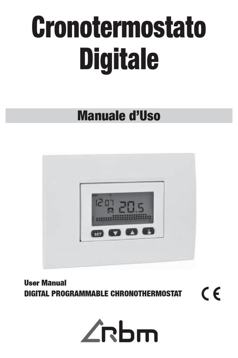
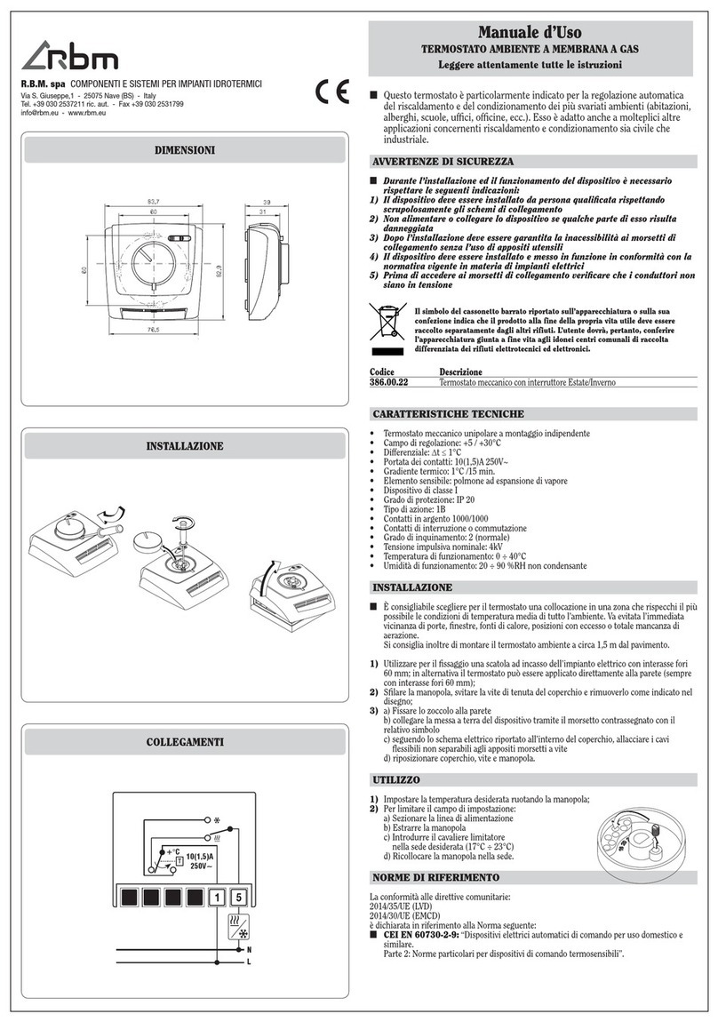
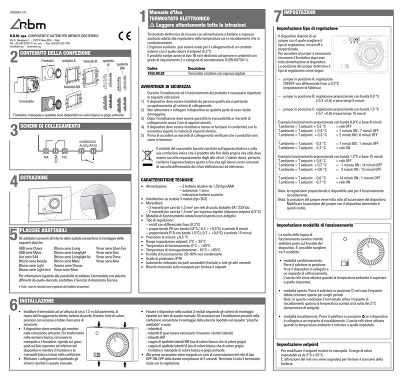
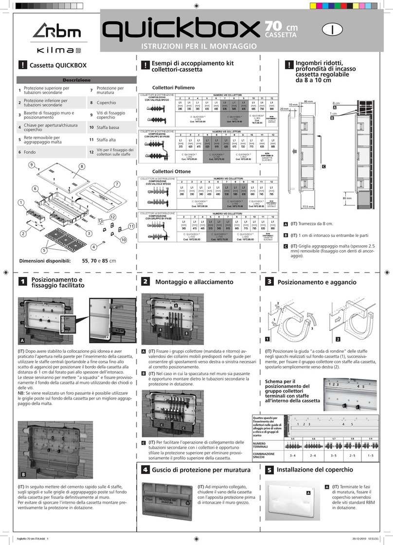
RBM Kilma Set Touch 2.0 User manual

TOUCH SCREEN DISPLAY
with built-in Wi-Fi interface and temperature
and humidity sensor.
USER GUIDE
Rev. Manual 03 - firmware version 1.49 del 16/01/2023

2 3MI3508.0_03 EN MI3508.0_03 EN
INDEX
4
5
10
12
16
19
19
21
23
25
26
27
31
33
33
INTRODUCTON
1.ZONES
1.1 Zones with Air-Quality Sensor
(VOC)
2.TIMERS
3. MECHANICAL EXTRACT
VENTILATION (MEV)
4.HEAT/COOL and ON/OFF
SYSTEM SWITCH
4.1 ON/OFF System Switch
4.2 Heat-Cool System Switch
5.DOMESTIC HOT WATER
6.ALARMS
7.SETTINGS
7.1 Change Homepage
7.2 Update Via Network
7.3 Screen brightness
7.4 Online Manual
34
35
35
37
37
37
38
38
40
40
43
45
46
47
8.ADVANCED SETTINGS
8.1 Echo Display
8.2 Change Alpha/Beta Mode
8.3 Reread Master
8.4 Reboot
8.5 Update Via USB
8.6 Installer Password
8.7 Service Password
Annex I – WI-FI CONNECTION
1. Wi-Fi connection wizard
2. Advanced settings
3. Wi-Fi connection of Beta display
Summarised table of errors
Annex II – FAILED COMMUNICATION
TOUCH SCREEN DISPLAY
with built-in Wi-Fi interface and temperature
and humidity sensor.
USER GUIDE
Rev. Manual 03 - firmware version 1.49 del 16/01/2023

4 5MI3508.0_03 EN MI3508.0_03 EN
INTRODUCTION
1. ZONES
The touch screen display is a user-friendly interface allowing you to use the controller of the system it is installed on. The display
has a Wi-Fi interface to connect to the remote management system and a temperature and humidity sensor to manage the zone
of the system where it is installed.
The display does not require specific programming as it automatically acquires the configuration of the controller it is connected
to.
Once the display has been installed and powered, it shows the Home page. If the Home page remains idle (no button is pressed
to enter a menu) for more than 30 seconds, the display goes into standby mode (black screen): to reactivate it, simply press
anywhere on the display.
Whereas if you enter one of the menus on the Home page (and then the subsequent submenus), but no other button is pressed
for more than 30 seconds, the display goes back to the previous screen. When another 30 seconds have elapsed, it goes back
to the previous screen and so on until it reaches the Home page. After a further 30 seconds idle, it returns to standby.
The Home page of the display has various buttons (identified by a black box) and icons. The icons are view-only and do not allow
editing, while the buttons allow the user to edit the settings inside of them.
The buttons and icons will be explained in detail below.
Clicking the Zone button on the “Home” page opens the “Zone List” section where the zones that were programmed in the
controller appear:
The controller can manage as many as 32 zones. If the system has more than 8 zones, they will not all fit on the same page of
the touch screen display and therefore other pages will be created in the “Zone List” section:
• Home: at the top left of the screen there is always an
indication of the menu that you are operating in;
•Wi-Fi and Time are indicated at the top right: if the Wi-Fi
is not yet connected, the time is acquired directly from the
controller that the display is connected to; if the Wi-Fi is
connected, the time is acquired directly from the Internet;
Daylight Saving Time and Standard Time are updated
automatically;
• The Zone Button grants access to the list of zones configured
in the controller;
• The MEV Button grants access to management of the MEVs
that the controller can manage; if the controller does not
manage any MEV, the button does not appear;
• The Timer Button grants access to the list of zone timers
(not the one of domestic hot water) that have been enabled
in the controller; if the system does not include timers, if the
controller does not manage any timer, the button does not
Image 1: “Home” page
appear;
• The Heat/Cool Button grants access to the heating and
cooling switch menu and to system ON/OFF (except for
domestic hot water);
• The Domestic Hot Water Button grants access to editing of
the temperature set points of hot water and relative timer.
• Two icons can be seen in the middle of the display at
the bottom: the Domestic Hot Water Temperature
(water droplet and thermometer) and the Outdoor Air
Temperature (home and thermometer), if present;
• The Alarm button is only present if there are alarms in
progress not yet cleared;
• The Settings Button (which can be password-protected)
grants access to the Wi-Fi settings and to the advanced
settings explained in detail at the end of this document.
NOTE Whether or not all the illustrated buttons and icons are always displayed depends on the type of system. For example:
• If the system does not include domestic hot water production, the relative domestic hot water tank temperature button
and icon will not be displayed;
• If the system is made only for heating, the summer season cannot be set;
• If there are no alarms in progress, the alarm button will not appear;
• If the Mechanical Extract Ventilation is not present, the relative button will not appear.
CAUTION: The Wi-Fi settings are provided separately in Annex I at the end of this document!
Image 2: “Zone list” screen
Image 3: “Zone list” screen with more than 8 zones
Image 4: “Zone list” screen with more than 8 zones

6 7MI3508.0_03 EN MI3508.0_03 EN
Clicking any of the zones opens the zone settings screen. The example shows “Zona 1”:
From the screen of the Previous image, it is possible to:
• View whether the zone is off, on, but not active, or on and active (ON) and if on in which work mode (Comfort or Economy).
If the zone is ON, it means that the ambient temperature set point has not been reached (Previous image), if the ON icon
does not appear, the zone might have reached the ambient set point, therefore is on, but not active (in the following image,
in winter the set point 24.0°C is lower than the ambient temperature detected 27.7 °C, therefore the zone is not active);
• View the humidity % (if there is a humidity sensor);
• Clicking the “Adjust set point” button or else clicking the current ambient temperature of the zone once, grants access to
the “Set Temperature” screen (Images 8 and 9), where the ambient temperature set point can be set in Comfort mode (Image
8, press the button with the word Comfort and orange heart) and/or Economy mode (Image 9, press the button with the
word Economy and Green leaf) pressing “+” to increase or “–“ to decrease the set point. Click the Confirm button to go back
to the previous screen, saving the entered changes or else press Undo to eliminate them;
• From the zone screen (see Image below) click the Work Mode button (at the bottom left) to access the “Set Work Mode”
screen.
If the ON icon does not appear and the Off work mode is indicated above the current ambient temperature, the zone might
be off because the entire system is off or because the timer associated to the zone is in the time slot whose intended work
mode is Off;
LEGENDA
Indication of the zone that you are operating in with editable
name
Indication of the work mode
Indication of humidity %
Indication that the zone is ON and active
Indication of the current Ambient temperature
Indication of the current work mode
Indication of the Ambient temperature set point
Image 5: Example screen of an ON and active type zone
in summer mode
1
1
2
3
4
5
6
7
2
3
4
5
6
7
Image 6: Example screen of zone without ON icon
because the set point has been reached
Image 7: Example screen of an off type zone
Image 8: “Set temperature” screen in Comfort work
mode
Image 9: “Set temperature” screen in Economy work
mode
Image 10: “Zone 1” screen in automatic Comfort mode
LEGENDA
Indication of the current work mode (not forced)
1
1

8 9MI3508.0_03 EN MI3508.0_03 EN
From the screen displayed in the following Image, you may Override the work mode of the zone to Comfort, Economy or Off.
By leaving Automatic, the work mode of the zone remains that defined by the timer associated to that zone:
- Clicking the Timer Button from the screen displayed in Image 12 grants access to the Weekly Program of the timer associated
to the Zone. From this screen you may Edit the weekly program by clicking the Edit Program Button:
See chapter 2 Timers for a detailed explanation of how to program the timer. Furthermore, if no timer was associated to the
zone, then the Timer Button will not appear in the zone screen:
Lastly, the names of the zones can be edited directly from the display by clicking the pen on the right of the words “Zona
1”:
When the zone is Overridden, this has priority over overriding the timer (which will be illustrated in chapter 2). Therefore if, as
in the example in Image 12, the zone is overridden to Economy, but the timer is overridden to Comfort, overriding to Economy
has priority over Comfort. The zone will remain in Override Economy until the user removes the override.
- Clicking the Humidity Set point button from the screen displayed in Image 12, it is possible to edit the humidity set point
by clicking “+” to increase it or “–“ to decrease it:
Image 11: “Set Work Mode” screen of the zone where
you are operating
Image 12: “Zone 1” screen in Overridden Economy
mode
LEGENDA
Indication of the current work mode (Force Economy)
1
1
Image 13: “Adjust Humidity Set point” screen
NOTE This button only appears if the zone is associated to a temperature and humidity sensor.
Image 14: “Weekly Program” screen of the timer
associated to the zone
Image 15: “Living room” zone screen without associated timer
Image 16: Screen to edit the name of the zone
CAUTION: Let’s imagine having 4 zones (Living Room, Kitchen, Bedroom and Bathroom) where Kitchen and Living
Room are paired to timer 1 (Day Zone), while Bedroom and Bathroom are paired to timer 2 (Night zone). Entering the
Kitchen Zone and from here in the timer, by making changes in the weekly programming, these changes will also apply
to the Living room zone as they are paired to the same Day Zone timer. Therefore, also directly entering the Day zone
timer from the Timer button on the Home page, the user will find the same changes that were made inside the Zones.

10 11MI3508.0_03 EN MI3508.0_03 EN
The NUM button grants access both to numbers and special characters. Once the description has been modified, press the
Button with the green tick to confirm or the one with the red X to undo the changes and exit the menu.
CAUTION: If the name of the zone was selected among the default descriptions and not among the free ones, the
name cannot be edited from the display, and therefore the pen to the right of the zone name will not be displayed.
The system can manage up to eight ambient air quality sensors. If a zone is associated to an air quality sensor, entering the page
of the zone will display the following screen:
The ppm (parts per million) data are relative to the amount of CO2detected by the AQ (Air Quality) probe and the ppb (parts
per billion) data are relative to the amount of volatile compounds, called VOC, (alcohol, acids, hydrocarbons, etc.) detected by
the AQ (Air Quality) probe. Clicking the CO2set point button displays the screen where you may adjust the set points regarding
CO2both in Economy and Comfort mode:
Image 17: Screen with Zone managed by air quality
probe
Image 18: Screen with Zone managed by air quality
probe
1.1 ZONES WITH AIR-QUALITY SENSOR (VOC)
Clicking the Comfort Button allows you to adjust the set point to activate the Comfort mode:
Clicking the Economy Button shown in image 17 allows you to modify the work mode of the zone:
For example, clicking Overridden Comfort can display the following screen:
Image 19: Screen with Zone managed by air quality probe
Image 20: Setting of zone work mode
Image 21: Screen with Zone managed by air quality probe
in Force Comfort work mode

12 13MI3508.0_03 EN MI3508.0_03 EN
Since the CO2detected is lower than the limit of Economy (800 ppm) the first threshold remains that of Economy mode, whereas
if the threshold is exceeded, the limit becomes 1500 ppm, namely that of the Comfort mode.
Lastly, the names of the zones can be edited directly from the display by clicking the pen to the right of the word “Cucina”:
The NUM button grants access both to numbers and special characters. Once the description has been modified, press the
Button with the green tick to confirm or the one with the red X to undo the changes and exit the menu.
Image 22: Screen to edit the name of the zone
CAUTION: If the name of the zone was selected among the default descriptions and not among the free ones, the
name cannot be edited from the display, and therefore the pen to the right of the zone name will not be displayed.
2. TIMERS
Clicking the Timer Button allows you to enter the screen with the List of timers:
Image 23: “Timers List” screen
Selecting the timer that you want to make changes to opens the screen of the selected timer where different hourly programming
can be set for each day or the same programming set from Monday to Friday or from Monday to Sunday:
Six different programs can be set for each day (or group of days), for example:
• 6:00 - Economy program
• 8:00 - Comfort program
• 10:00 - Economy program
• 19:00 - Comfort program
• 21:00 - Economy program
• 23:00 – Off
By entering in the day (or group of days) and selecting the existing programs, you may modify their start time (by pressing “+”
or “–“), work mode (by pressing either Comfort, Economy or Off) or delete the program (Image 27). Clicking the Add Variation
Button (Image below) allows you to add other programs, up to a maximum of 6:
By selecting the Edit Program Button, you may make changes to the desired days:
Image 24: “Weekly Program” screen of selected timer
Image 25: Screen to select the days to edit
Image 26: Screen inside the group of days [Mon-Friday]
to be edited

14 15MI3508.0_03 EN MI3508.0_03 EN
Once changes have been made in Set Variation, press the Confirm Button to go back to the previous screen saving the changes
or else press Undo to cancel them:
Press the Confirm Button to go back to the Weekly Program screen. Click the Edit Parameters Button to separately modify
Saturday and Sunday.
Clicking the Set Work Mode Button on the left of the Edit program Button, opens the Set Work Mode screen of the timer
(Image 30) so as to Override the timer in Comfort, Economy or Off mode.
When the timer is overridden in Economy mode, for example, though the Weekly program is in Comfort mode (at 11:34) the
entered mode will be Economy (indicated by the Set Work Mode Button on the left of the Edit Program button in the following
Image):
You do not need to enter times in chronological order, therefore if you enter:
• 10:00 - Economy program
• 8:00 - Comfort program
• 6:00 - Economy program
• 19:00 - Comfort program
• 23:00 – Off
• 21:00 - Economy program
The system will put them in order automatically:
• 6:00 - Economy program
• 8:00 - Comfort program
• 10:00 - Economy program
• 19:00 - Comfort program
• 21:00 - Economy program
• 23:00 – Off
If two consecutive times are entered with the same work mode, for example Comfort at 8:00 and Comfort at 10:00, then the
second time will automatically be joined to the previous one.
When the 6 daily programs have been reached, the Add Variation Button will disappear:
LEGENDA
Indication of the selected work mode
Increase hour or minutes
Decrease hour or minutes
Delete the timer variation
Select the variation work mode
Undo the setting you have done
Confirm the setting you have done
Image 27: “Set Variation” of an existing program screen
1
2
3
4
5
6
7
4
5 6 7
1
3 2
Image 28: Screen with all 6 daily programs set
Image 31: Example of timer in Overridden Comfort in
Economy time
LEGENDA
Indication of the selected work mode
Image 29: “Weekly program” screen of selected timer
Image 30: “Set Work Mode” screen of selected timer
1
1
1
1
CAUTION: The timer will remain in Economy until the work mode is restored to Automatic or overridden by the user
to work in another mode!
Remember that the override of the timer is secondary with respect to override of the zone. Therefore, if the override of
the Zone is Comfort and the override of the timer is Economy, the zone will acquire the set points of the Comfort mode.

16 17MI3508.0_03 EN MI3508.0_03 EN
Lastly, the names of the timers can be edited directly from the display by clicking the pen to the right of the words “Camera 7”: Clicking the MEV Button opens the MEV List screen if the system manages more than one MEV:
Select from the “MEV List” screen the one whose parameters you wish to edit or check. If the system only manages one MEV,
then you enter directly into the screen of the only existing MEV:
In the previous image, the icons in the middle respectively indicate, starting from the left:
a. MEV active (air renewal active);
b. Dehumidification in progress, if the MEV is not dehumidifying, the icon with the crossed-out droplet will not appear;
c.The MEV is integrating the heating or cooling system; the icon disappears if integration is not requested or has not been
programmed;
d. Selected speed: low, medium, high or automatic.
The icons “a”, “b” and “c” cannot be edited by the user, but only viewed, while parameter “d” can be edited using the
following buttons:
The NUM button grants access both to numbers and special characters. Once the description has been modified, press the
Button with the green tick to confirm or the one with the red X to undo the changes and exit the menu.
Image 32: Screen to edit the name of the timer Image 35: “MEV List” screen
Image 36: Screen of a MEV
Image 37: Selection of speeds (from left): automatic,
low, medium and high
CAUTION: If the name of the timer was selected among the default descriptions and not among the free ones, the
name cannot be edited from the display, and therefore the pen to the right of the timer name will not be displayed.
3. MECHANICAL EXTRACT VENTILATION (MEV)
The MEV Button is only displayed if the controller was programmed to manage a Mechanical Extract Ventilation system.
Image 33: Home page with programmed MEV
Image 34: Home page without programmed MEV

18 19MI3508.0_03 EN MI3508.0_03 EN
Pressing the Exit Button returns to the MEV List screen and then to the Home page.
If by selecting the MEV Button the following image is displayed, it means that the main switch to enable the MEV is off or that
the timer program associated to the MEV is at off:
Clicking the MEV Timer Button allows you to enter the Weekly Ventilation Program:
For the changes and functions of the timers, see chapter Timers.
Image 38: “Camera 5” MEV off screen
Image 39: “Camera 5” MEV screen
Image 40: Weekly Ventilation Program
Lastly, the names of the MEV itself can be edited directly from the display by clicking the pen to the right of the words “Camera 5”:
The NUM button grants access both to numbers and special characters. Once the description has been modified, press the Button
with the green tick to confirm or the one with the red X to undo the changes and exit the menu.
Image 41: Screen to edit the name of the MEV
CAUTION: If the name of the MEV was selected among the default descriptions and not among the free ones, the
name cannot be edited from the display, and therefore the pen to the right of the MEV name will not be displayed.
4. HEAT/COOL AND ON/OFF SYSTEM SWITCH
To switch the system ON or OFF, press the Button at the bottom left of the Home page (indicated by the arrow):
Image 42: Home page with indication of System Off
4.1 ON/OFF SYSTEM SWITCH

20 21MI3508.0_03 EN MI3508.0_03 EN
Within the “System Switch-ON” menu, you may switch on the system by clicking the selector in the Enable System icon and
setting it at ON (Image 43), or else switch off the system by setting the selector at OFF (Image 44). When the selection has been
made, press the Exit Button to go back to the Home page.
Image 43: “System Switch-on” with Enable System
button at ON screen
Image 45: Home page with System Off by other causes
Image 44: “System Switch-on” with Enable System
button at OFF screen
NOTE FOR
INSTALLER
Switching the system on and off can depend on various factors. Indicate to the end user which one affect swi-
tching the system ON/OFF in the specific case:
• Presence of a calendar
• Presence of an external dry contact
• Outdoor temperature
• Setting of the user from the touch screen display
If the following Home and System switch-on screens appear (image 45 and 46) contact your installer for further
information.
Heat/cool switching is only possible if the controller the display is connected to has been programmed to manage both summer
and winter. If one of the two seasons is not set, selecting the Button at the bottom left of the Home page and entering the
“System switch-on” menu, the Summer and Winter icons will not be displayed.
Image 47: “Home” page with system in winter season
Image 48: “System switch-on” screen of a Winter only
or Summer only system (the seasons do not appear as
only one is possible)
Image 46: System Switch-on Screen with System Off by
other causes
4.2 HEAT-COOL SYSTEM SWITCH

22 23MI3508.0_03 EN MI3508.0_03 EN
Only if both seasons can be set will both be displayed in the System Switch-On Menu:
When the required season has been selected, press the Exit Button to go back to the Home page. You will notice that the
Button at the bottom left of the Home page will have switched from Winter (snowflakes) to Summer (sun) or vice versa:
Image 49: “System Switch-on” screen of a Summer and
Winter system at ON
Image 52: System Switch-on Screen
Image 51: Home page of a system in Summer mode
Image 50: “System Switch-on” screen of a Summer and
Winter system at OFF
NOTE FOR
INSTALLER
Switching the system from Cooling to Heating and vice versa can depend on several factors. Indicate to the end
user which one affect switching of the system in the specific case:
• Presence of a calendar
• Presence of an external dry contact
• Outdoor temperature
• Setting of the user from the touch screen display
In fact, the screen in the following image does not only appear when the system is in heating only or cooling
only mode, but also if heat/cool is switched by an external dry contact.
5. DOMESTIC HOT WATER
The Domestic hot water button is only displayed if the controller is programmed for its management:
Clicking the Domestic Hot Water Button on the Home page opens the “Domestic Hot Water Setting” screen:
Image 53: Home page with system that manages
domestic hot water
Image 54: “Domestic Hot Water Setting” screen in
Comfort Mode without Timer

24 25MI3508.0_03 EN MI3508.0_03 EN
From this screen you may:
• Press the DHW Enable Button selector, enable (ON) or disable (OFF) production of domestic hot water;
• Select the Comfort button and then press the “+” and “-“ buttons, adjust the set point in Comfort work mode (previous
image);
• Select the Economy button and then press the “+” and “-“ buttons, adjust the set point in Economy work mode (next image).
When you have entered the settings, press the Confirm button to save the changes or Undo to cancel them. If DHW is at OFF,
the Domestic Hot Water Settings screen will be empty except for the DHW Enable button:
And the Home page will display the screen with the following image with an icon of the crossed-out droplet in the Domestic
Hot Water Button:
Image 55: “Domestic Hot Water Setting” screen in
Economy mode
Image 56: “Domestic Hot Water Setting” screen at OFF
Image 57: Home page with Domestic Hot Water off
If production of domestic hot water was paired to a timer when programming the controller, the “DHW Timer” button appears
on the left of the Comfort Button:
Click the DHW Timer to enter the “Weekly Program” screen. From here you can set a different hourly programming for each
day or the same programming from Monday to Friday or from Monday to Sunday. Refer to the Timers chapter for instructions
on weekly programming.
Image 58: “Domestic Hot Water Setting” screen with
paired timer
6. ALARMS
The Alarms Button is only displayed if there are alarms that have not been cleared.
Clicking the Alarms Button will list all of the triggered alarms. When they have been cleared, the button will disappear when
you go back to the Home page.
Image 59: “Home” page with alarms in progress
Image 60: “Triggered alarms” screen with list of alarms
in progress

26 27MI3508.0_03 EN MI3508.0_03 EN
Image 61: “Home” page without alarms in progress
CAUTION: The installer is required to clear the alarms.
7. SETTINGS
Click Settings to enter the User Settings screen:
The Wi-Fi Connection Button will be dealt with in Annex I at the end of this document, the Advanced Settings button in the
next Chapter.al Capitolo successivo.
Image 62: User Settings screen
The Change Homepage Button allows you to view the Thermal Power Station Home for the installer:
If an installer password has been set (System Settings), they will be prompted to continue:
Once entered, it is not requested for five minutes even if you go back to the Home page and to the Thermal Power Station
Home page.
The System On/Off (seasonal change), Domestic Hot Water, Alarms and Settings Buttons have the same menus as those seen
in the previous chapters.
Clicking the Circuits Button displays the screen with the list of configured circuits:
Image 63: Thermal Power Station Home page
Image 64: Installer password input screen
Image 65: Configured Circuits List screen
7.1 CHANGE HOMEPAGE

28 29MI3508.0_03 EN MI3508.0_03 EN
Clicking the desired circuit opens the following screen:
Clicking the Summer Button will open:
This menu displays some information about the circuit and allows editing the water temperature set points both in winter and
in summer. The previous images show that the circuit is managed by a compensation curve in winter, and a direct set point in
summer.
By clicking the Edit Button, if the Winter Button is selected, you may only edit the set point of the Economy and Comfort
curves:
By clicking the Edit Button, if the Summer Button is selected, you may only edit the set point of the Economy and Comfort
direct set point:
Press Confirm if you want to save the changes made or Undo to cancel them.
Clicking the Generators Button displays the screen with the list of generators present in the system:
The following are displayed at the top starting from the left:
• the set points of the winter curve both in Economy mode and in Comfort mode, respectively at -10 °C, 0 °C, +10 °C and +20
°C and the set points of the direct set point in both Economy and Comfort mode;
• set winter or summer offset, if any (0.0 °C)
• water temperature set point (26.0 °C)
• current water outlet temperature (28.1 °C)
• opening of the mixing valve (V: -26.9% as reference for valves 0/10V; VA=0 and VC=0 as reference for 3-point valves);
• enabling of the water pumps (PA and PB)
• current work mode(COMF+HEAT+ACT)
Image 66: Winter Circuit screen
Image 67: Summer Circuit screen
CAUTION: From this menu it is not possible to switch from circuit management with compensation curve to management
with direct set point and vice versa. This step must be carried out by acting directly on the controller.
Image 68: Circuit screen detail
Immagine 69: Impostazione dei valori delle curve
invernali
Image 70: Summer direct set point values setting
Image 71: Generators Information screen

30 31MI3508.0_03 EN MI3508.0_03 EN
It is not possible to edit on this page, but it displays:
• the set point temperature of each generator
• the temperature read by the reference probe of the generator (if installed);
• whether the generator is enabled and/or active;
• THE 0/10V signal sent to set the generator set point (ignore this parameter if it is not used);
• Summer and Winter outdoor temperatures working limits;
• whether the generator has been degraded;
• the timer countdown of the degradation in seconds;
• the type of degradation selected (inclusive or exclusive in summer and in winter).
Clicking the button Next the cascade generators will be displayed (gas boilers via Opentherm communication and HPs via
Modbus RTU):
It is not possible to edit on this page, but it displays:
• generator enabling: OFF not enabled, 110 enabled in DHW, heating and cooling; 101 enabled only in cooling; 102 enabled in
heating only; 010 enabled only in DHW;
• RAC: indicates the current request where R stands for Heating, A for DHW and C for cooling;
• Temp and Pot. R indicate the required temperature and power;
• Status indicates the status of the generator (combination of 8 bits status, refer to the manufacturer’s manual and the
implemented firmware);
• Temperatura di mandata, ritorno e ACS lette dal generatore se presenti le relative sonde di temperatura a bordo;
• Water outlet, inlet and DHW temperature read by the generator if the relative temperature probes are present on board;
• Pot. is the power in % or kW delivered or absorbed by the generator (refer to the manufacturer’s manual and the implemented
firmware)
• Err indicates the current alarms (combination of 8 alarm bits, refer to the manufacturer’s manual and the implemented
firmware);
• OEM indicates the generator specific error, refer to the manufacturer’s manual.
Clicking the Diagnostics Button displays the screen with the list of free temperatures and signals present in the system:
It is not possible to edit on this page, but it displays:
• the values (°C) and the descriptions of the free temperatures detected and the input they are connected to (ChA);
• the values (ON/OFF) and the descriptions of the free alarm signals and the input they are connected to (ChEr);
• the values (ON/OFF) and the descriptions of the free digital signals and the input they are connected to (ChD).
To go back to the Home page, simply press the Settings button and then the Change Homepage Button from the Thermal
Power Station Home page. This operation does not require a password.
Image 72: Cascade genetors informazion screen
Image 73: Diagnostics Information screen
The Update via Network Button allows you to update the firmware to the most recent version. Before launching the update
via Network, the Wi-Fi connection must be connected to the Internet (see Annex I):
Whereas if the following screen appears, it means that there are more recent versions: the Firmware Revision number is higher
or the date is more recent.
If the following screen appears, it means that there are no more recent versions available:
Image 74: First Screen after having clicked Update via
Network
Image 75: No Firmware update available
7.2 UPDATE VIA NETWORK

32 33MI3508.0_03 EN MI3508.0_03 EN
Image 76: Screen showing the latest update available
respect to the current/installed version.
Image 77: The firmware is downloaded.
Image 78: The firmware is copied.
Image 79: Screen that appears if the update fails or is
cancelled.
Image 80: Screen that appears if the update is
interrupted while overwriting the firmware.
If you touch the screen during the download or copy of the firmware, the update is cancelled without consequences:
If the update is interrupted while the moon is uploading on the screen (the system is overwriting the new firmware) then the
system will have an inconsistent firmware (half updated and half no). Two options will appear: RETRY? or DFU?
RETRY means to try again to download the update via Wi-Fi, while DFU means proceed with the update via USB (operation to
be carried out by a specialised technician).
Clicking Screen brightness allows you to increase “+” or decrease brightness “-“:
Clicking the Online Manual Button allows you to view this document by scanning the QR code:
Image 81: Screen for adjusting screen brightness
Image 82: Manual QR Link
7.3 SCREEN BRIGHTNESS
7.4 ONLINE MANUAL

34 35MI3508.0_03 EN MI3508.0_03 EN
CAUTION: Only access this page if required and guided by a skilled technician. Incorrect settings could cause the system
to malfunction.
8. ADVANCED SETTINGS
Before accessing, the Service password is requested (which corresponds to the System Configuration password). If no password
was configured, the screen shown in the following image will still be displayed. In this case the default password is 00000.
Whereas if the Service password has been configured, it must be entered or else it will be impossible to access advanced
settings:
Following access, this screen appears:
The Firmware Release matches the current revision loaded on the touch screen display; in the previous Image, R 01.40 is the
Firmware Revision number followed by the date (Feb 11 2021). While DOT Mk2 corresponds to the model of the PCB board of
the touch screen display.
The Calibrate Touch Button is a function intended for the manufacturer. Changing this menu could jeopardise the correct
operation of the touch screen display.
Image 83: Access screen to Advanced Settings
Image 84: Advanced Settings Screen for a touch screen
display
The Echo Display Button allows you to virtually interact with the controller by viewing the controller itself on the touch screen
and operating the same buttons (+; -; ESC and OK) as indicated in the following image:
From version 1.4, you may connect two displays on the same system by pressing the Change Alpha/Beta Mode Button. By
default, all the displays produced are programmed to be display 1. Clicking the Button displays the following screen:
It is always possible to connect to each master controller two and only 2 displays, but as display 1 it is possible to select ALFA
or ALFA 2. In both cases the Wi-Fi will be active, but the reference sensor inside the display will be TH 223 if ALFA is selected,
TH221 if ALFA 2 is selected. If BETA is selected the operation has success only if on the controller display 2 is enable. The Wi-Fi
is deactivated on the Beta display as only the first display will be online and is characterised by the Greek letter “ß” in red at the
top right in place of the Wi-Fi icon which on the other hand characterises display 1 (Alpha):
Entering this menu allows you to edit all the parameters of the controller.
Image 85: “Echo display” screen viewed on the touch
screen display.
Image 86: Alpha 1 or 2/Beta work mode
8.1 ECHO DISPLAY
8.2 CHANGE ALPHA/BETA MODE

36 37MI3508.0_03 EN MI3508.0_03 EN
Image 87: Home page from display 2
Image 88: Thermal Power Station Home page from
display 2
Image 89: Alpha work mode
Accordingly, if there are two displays in a system, the Home page can be viewed in both (one will have the Wi-Fi icon and the
other the letter “ß”) or in the Alpha display (or Alpha 2), the Home page (Wi-Fi icon) and in the Beta display the Thermal Power
Station Home page (letter “ß”). All the menus remain unchanged for the Beta display.
The word TH222 in image 86 means that, if you want to use the sensor on the touch screen display which acts as the Beta display
to manage a zone, the temperature and humidity sensor TH222 must be paired to that zone.
The display can be restored as number 1 (Alpha or Alpha 2) by simply clicking the Alpha/Beta mode Change button again:
Here again the operation is successful if display 1 is enabled on the controller. The word TH223 in the previous image means that,
if you want to use the sensor on the touch screen display which acts as the Alpha display to manage a zone, the temperature
and humidity sensor TH223 must be paired to that zone.
CAUTION: If Beta mode is set unintentionally without having enabled display 2 on the controller, if you go on Advanced
setting is it possible to restore the display as display 1 (ALFA or ALFA 2).
The Reread Master Button allows you to reread the settings on the controller board which the display is connected to and if
different, changes will also be made immediately to the touch screen display:
The Reboot Button allows you to switch the display off and back on (like when switching electricity on and off). When switched
back on, the following screen appears:
The Update via USB Button allows you to update the firmware to the most recent version by physically connecting to the touch
screen display (operation to be carried out by a specialised technician):
Image 90: Screen displayed during rereading of the
board
Image 91: Display reboot screen
Image 92: Screen that appears by clicking the Update
Via USB Button
8.3 REREAD MASTER
8.4 REBOOT
8.5 UPDATE VIA USB

38 39MI3508.0_03 EN MI3508.0_03 EN
Clicking the Installer Password Button allows you to set the new Installer password (which corresponds to the System Settings
password) in order to limit access to the Thermal Power Station Home page:
Even entering password 00000, you will still be prompted to enter the Advanced settings menu.
The Service Password button allows you to edit the password to enter the Advanced settings menu (System Configuration):
Entering password 00000 opens the following screen:
Image 93: Screen to set installer password
Image 95: Screen to set service password
Image 94: Password removed
8.6 INSTALLER PASSWORD
8.7 SERVICE PASSWORD
Image 96: New password set
This manual suits for next models
1
Table of contents
Other RBM Thermostat manuals
Popular Thermostat manuals by other brands

DEVI
DEVI devireg 530 installation guide

Lux Products
Lux Products PSDFC159 Installation and operating instrictions

Venstar
Venstar ColorTouch T5800 Owner's manual and installation instructions

Honeywell
Honeywell CT3200 series Installation and programming instructions

Robertshaw
Robertshaw Smart Sense Series installation manual

American Standard
American Standard Enfield T373.730 Features & dimensions