Manuale d’Uso
TERMOSTATO AMBIENTE A MEMBRANA A GAS
Leggere attentamente tutte le istruzioni
■Questo termostato è particolarmente indicato per la regolazione automatica
del riscaldamento e del condizionamento dei più svariati ambienti (abitazioni,
alberghi, scuole, ufci, ofcine, ecc.). Esso è adatto anche a molteplici altre
applicazioni concernenti riscaldamento e condizionamento sia civile che
industriale.
AVVERTENZE DI SICUREZZA
■Durante l’installazione ed il funzionamento del dispositivo è necessario
rispettare le seguenti indicazioni:
1) Il dispositivo deve essere installato da persona qualicata rispettando
scrupolosamente gli schemi di collegamento
2) Non alimentare o collegare lo dispositivo se qualche parte di esso risulta
danneggiata
3) Dopo l’installazione deve essere garantita la inacessibilità ai morsetti di
collegamento senza l’uso di appositi utensili
4) Il dispositivo deve essere installato e messo in funzione in conformità con la
normativa vigente in materia di impianti elettrici
5) Prima di accedere ai morsetti di collegamento vericare che i conduttori non
siano in tensione
Codice Descrizione
386.00.22 Termostato meccanico con interruttore Estate/Inverno
CARATTERISTICHE TECNICHE
• Termostato meccanico unipolare a montaggio indipendente
• Campo di regolazione: +5 / +30°C
• Differenziale: t 1°C
• Portata dei contatti: 10(1,5)A 250V~
• Gradiente termico: 1°C /15 min.
• Elemento sensibile: polmone ad espansione di vapore
• Dispositivo di classe I
• Grado di protezione: IP 20
• Tipo di azione: 1B
• Contatti in argento 1000/1000
• Contatti di interruzione o commutazione
• Grado di inquinamento: 2 (normale)
• Tensione impulsiva nominale: 4kV
• Temperatura di funzionamento: 0 ÷ 40°C
• Umidità di funzionamento: 20 ÷ 90 %RH non condensante
INSTALLAZIONE
■È consigliabile scegliere per il termostato una collocazione in una zona che rispecchi il più
possibile le condizioni di temperatura media di tutto l’ambiente. Va evitata l’immediata
vicinanza di porte, nestre, fonti di calore, posizioni con eccesso o totale mancanza di
aerazione.
Si consiglia inoltre di montare il termostato ambiente a circa 1,5 m dal pavimento.
1) Utilizzare per il ssaggio una scatola ad incasso dell’impianto elettrico con interasse fori
60 mm; in alternativa il termostato può essere applicato direttamente alla parete (sempre
con interasse fori 60 mm);
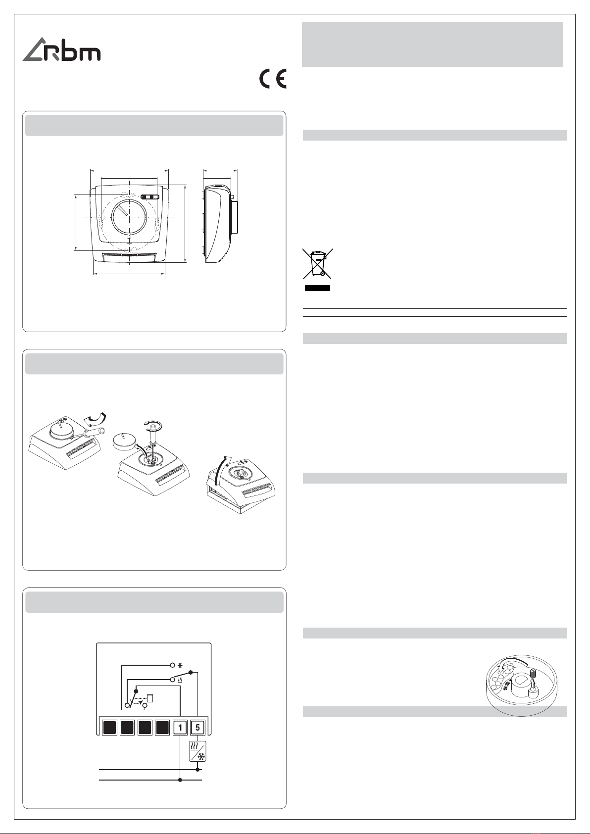
2) Slare la manopola, svitare la vite di tenuta del coperchio e rimuoverlo come indicato nel
disegno;
3) a) Fissare lo zoccolo alla parete
b) collegare la messa a terra del dispositivo tramite il morsetto contrassegnato con il
relativo simbolo
c) seguendo lo schema elettrico riportato all’interno del coperchio, allacciare i cavi
essibili non separabili agli appositi morsetti a vite
d) riposizionare coperchio, vite e manopola.
UTILIZZO
1) Impostare la temperatura desiderata ruotando la manopola;
2) Per limitare il campo di impostazione:
a) Sezionare la linea di alimentazione
b) Estrarre la manopola
c) Introdurre il cavaliere limitatore
nella sede desiderata (17°C ÷ 23°C)
d) Ricollocare la manopola nella sede.
NORME DI RIFERIMENTO
La conformità alle direttive comunitarie:
2014/35/UE (LVD)
2014/30/UE (EMCD)
è dichiarata in riferimento alla Norma seguente:
■CEI EN 60730-2-9: “Dispositivi elettrici automatici di comando per uso domestico e
similare.
Parte 2: Norme particolari per dispositivi di comando termosensibili”.
R.B.M. spa COMPONENTI E SISTEMI PER IMPIANTI IDROTERMICI
Via S. Giuseppe,1 - 25075 Nave (BS) - Italy
Tel. +39 030 2537211 ric. aut. - Fax +39 030 2531799
Il simbolo del cassonetto barrato riportato sull’apparecchiatura o sulla sua
confezione indica che il prodotto alla fine della propria vita utile deve essere
raccolto separatamente dagli altri rifiuti. L’utente dovrà, pertanto, conferire
l’apparecchiatura giunta a fine vita agli idonei centri comunali di raccolta
differenziata dei rifiuti elettrotecnici ed elettronici.
DIMENSIONI
83,7
76,5
82,9
60
60
31
39
INSTALLAZIONE
COLLEGAMENTI
T
+°C
N
L
10(1,5)A
250V~


