RBM 1552.00.02 User manual

6
1
5
3
2
4
7
V3IS00961-010
Termostato elettronico da incasso con alimentazione a batterie e ingresso
ausiliario adatto alla regolazione della temperatura sia in riscaldamento che in
condizionamento
L’ingresso ausiliario può essere usato per il collegamento di un contatto
esterno con il quale ridurre il setpoint di 3°C.
Il prodotto svolge azioni di tipo 1B ed è destinato ad operare in ambienti con
grado di inquinamento 2 e categoria di sovratensione III (EN 60730-1).
Codice Descrizione
1552.00.02 Termostato a batterie con ingresso digitale
AVVERTENZE DI SICUREZZA
Durante l’installazione ed il funzionamento del prodotto è necessario rispettare
le seguenti indicazioni:
1) Il dispositivo deve essere installato da persona qualificata rispettando
scrupolosamente gli schemi di collegamento.
2) Non alimentare o collegare il dispositivo se qualche parte di esso risulta
danneggiata.
3) Dopo l’installazione deve essere garantita la inacessibilità ai morsetti di
collegamento senza l’uso di appositi utensili.
4) Il dispositivo deve essere installato e messo in funzione in conformità con la
normativa vigente in materia di impianti elettrici.
5) Prima di accedere ai morsetti di collegamento verificare che i conduttori non
siano in tensione.
CARATTERISTICHE TECNICHE
• Alimentazione: – 2 batterie alcaline da 1,5V (tipo AAA)
– autonomia: 1 anno
– indicazione batterie scariche
• Installazione su scatola 3 moduli (tipo 503)
• Morsettiera:
– 3 morsetti per cavi da 1,5 mm2per relè di uscita bistabile 5A / 250 Vac
– 2 morsetti per cavi da 1,5 mm2per ingresso digitale (riduzione setpoint di 3°C)
• Modalità di funzionamento estate/inverno/spento (con antigelo)
• Tipo di regolazione:
– on/off con differenziale fisso (0,3°C)
– proporzionale P8 con banda 0,8°C (-0,3 ÷ +0,5°C) e periodo 8 minuti
– proporzionale P15 con banda 1,5°C (-0,7 ÷ +0,8°C) e periodo 15 minuti
• Precisione di misura: ±0,5 °C
• Range impostazione setpoint: 5°C ÷ 35°C
• Temperatura di funzionamento: 0°C ÷ +50°C
• Temperatura di immagazzinamento: -10°C ÷ +65°C
• Umidità di funzionamento: 20÷90% non condensante
• Grado di protezione: IP40
• Isolamento: rinforzato tra parti accessibili (frontale) e tutti gli altri morsetti
• Blocchi meccanici sulla manopola per limitare il setpoint
• Installare il termostato ad un’altezza di circa 1,5 m dal pavimento, al
riparo dall’irraggiamento diretto, lontano da porte, finestre, fonti di calore,
posizioni con eccesso o totale mancanza di
aerazione.
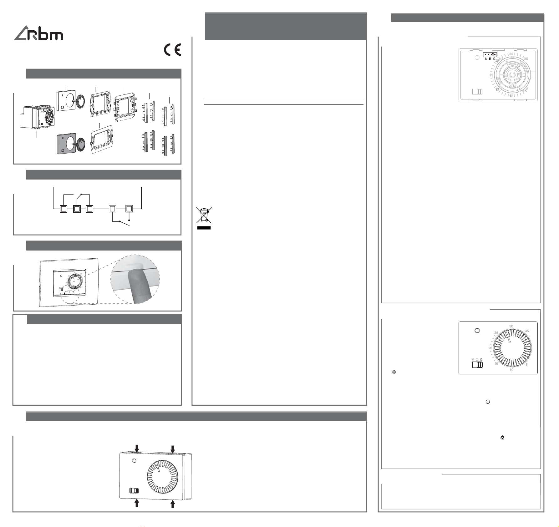
• Il dispositivo viene venduto già montato
nella colorazione antracite. Per trasformarlo
nella versione bianca, rimuovere la
manopola e il frontalino, agendo sui ganci
posti sul lato superiore ed inferiore del
dispositivo e montare il frontalino e la
manopola bianca inclusi nella confezione.
• Effettuare i collegamenti rispettando gli
schemi riportati in questo manuale.
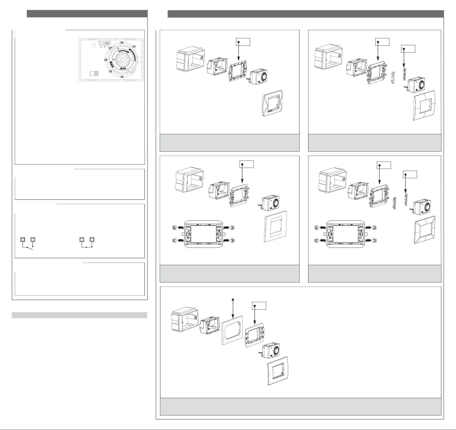
• Fissare il dispositivo nella scatola 3 moduli seguendo gli schemi di montaggio
riportati sul retro di questo manuale. Gli accessori per l’installazione presenti nella
confezione consentono il montaggio delle placche riportate nel riquadro “placche
adattabili” e sono:
- telaietto A
- telaietto B (può essere necessario rimuovere i dentini laterali)
- telaietto AIR
- coppia di spallette laterali BM (sia di colore bianco che di colore grigio)
- coppia di spallette laterali VI (sia di colore bianco che di colore grigio)
- frontalini e manopole di colore bianco e grigio antracite.
• Alla prima accensione viene eseguito un ciclo di commutazione del relè di tipo
OFF-ON-OFF della durata complessiva di 3 secondi. Terminato il ciclo il termostato
inizia con la regolazione.
Manuale d’Uso
TERMOSTATO ELETTRONICO
Leggere attentamente tutte le istruzioni
INSTALLAZIONE
R.B.M. spa COMPONENTI E SISTEMI PER IMPIANTI IDROTERMICI
Via S. Giuseppe,1 - 25075 Nave (BS) - Italy
Tel. +39 030 2537211 ric. aut. - Fax +39 030 2531799
Gli adattatori presenti all’interno della scatola consentono il montaggio delle
seguenti placche:
Per informazioni riguardo alla possibilità di adattare il termostato con placche
differenti da quelle elencate, contattare il Servizio di Assistenza Tecnica.
• Tutti i marchi riportati sono registrati dai legittimi proprietari.
ABB serie Chiara
ABB serie Mylos
Ave serie S44
Bticino serie Axolute
Bticino serie Light
Bticino serie Light tech
Bticino serie Living
Bticino serie Livinglight
Bticino serie Livinglight Air
Bticino serie Matix
Gewiss serie Chorus
Vimar serie Eikon
Vimar serie Eikon Evo
Vimar serie Idea
Vimar serie Plana
Vimar serie Arké
Il simbolo del cassonetto barrato riportato sull’apparecchiatura o sulla
sua confezione indica che il prodotto alla fine della propria vita utile deve
essere raccolto separatamente dagli altri rifiuti. L’utente dovrà, pertanto,
conferire l’apparecchiatura giunta a fine vita agli idonei centri comunali
di raccolta differenziata dei rifiuti elettrotecnici ed elettronici.
Impostazione tipo di regolazione
Impostazione modalità di funzionamento
Il dispositivo dispone di un
jumper con il quale scegliere il
tipo di regolazione, tra on/off o
proporzionale.
Per accedere al jumper è necessario
rimuovere il frontalino dopo aver
tolto alimentazione al dispositivo.
La posizione del jumper determina il
tipo di regolazione come segue:
− jumper in posizione A: regolazione
ON/OFF con differenziale fisso a 0,3°C
(impostazione di fabbrica)
− jumper in posizione B: regolazione proporzionale con banda 0,8 °C
(-0,3 +0,5) e base tempi 8 minuti
− jumper in posizione C: regolazione proporzionale con banda 1,5 °C
(-0,7 +0,8) e base tempi 15 minuti
Esempio funzionamento proporzionale con banda 0,8°C e base 8 minuti
T.ambiente = T.setpoint + 0,5 °C = relè OFF
T.ambiente = T.setpoint + 0,4 °C = 1 minuto ON ; 7 minuti OFF
T.ambiente = T.setpoint + 0,3 °C = 2 minuti ON ; 6 minuti OFF
...
T.ambiente = T.setpoint - 0,2 °C = 7 minuti ON ; 1 minuto OFF
T.ambiente = T.setpoint - 0,3 °C = relè ON
Esempio funzionamento proporzionale con banda 1,5°C e base 15 minuti
T.ambiente = T.setpoint + 0,8 °C = relè OFF
T.ambiente = T.setpoint + 0,7 °C = 1 minuto ON ; 14 minuti OFF
T.ambiente = T.setpoint + 0,6 °C = 2 minuti ON ; 13 minuti OFF
...
T.ambiente = T.setpoint - 0,6 °C = 14 minuti ON ; 1 minuto OFF
T.ambiente = T.setpoint - 0,7 °C = relè ON
Nota: la regolazione proporzionale è disponibile solo per il funzionamento
riscaldamento.
Nota: la posizione del jumper viene letta solo all’accensione del dispositivo.
Modificare la posizione del jumper con il dispositivo alimentato è
quindi inutile.
IMPOSTAZIONI
CONTENUTO DELLA CONFEZIONE
PLACCHE ADATTABILI
SCHEMI DI COLLEGAMENTO
ESTRAZIONE
termostato
Frontalino, manopola e spallette sono disponibili nei colori bianco e grigio antracite
Frontalini spallette
VI spallette
BM
telaietto A
telaietto AIR
telaietto B
La scelta della logica di
funzionamento avviene tramite
selettore posto sul frontale del
dispositivo. E’ possibile scegliere
tra 3 modalità:
• modalità condizionamento.
Porre il selettore in posizione
se il dispositivo è collegato a
un impianto di raffrescamento.
L’uscita relè viene attivata quando la temperatura ambiente è superiore
a quella impostata.
• modalità spento. Porre il selettore in posizione nel caso l’impianto
debba rimanere spento per lunghi periodi.
Nota: in questa condizione il termostato attiva l’impianto di
riscaldamento qualora la temperatura scenda al di sotto dei 2°C
(temperatura di antigelo).
• modalità riscaldamento. Porre il selettore in posizione se il dispositivo
è collegato a un impianto di riscaldamento. L’uscita relè viene attivata
quando la temperatura ambiente è inferiore a quella impostata.
Impostazione setpoint
Per modificare il setpoint ruotare la manopola. Il range di valori
impostabili va da 5°C a 35°C.
L’ attivazione del relè non viene segnalata per limitare il consumo della
batteria.
INGRESSO
AUSILIARIO
COM
NA NC
123 45

98
Bticino serie Matix
Bticino serie Living, Light, Light Tech, Livinglight, Axolute
Vimar serie Eikon, Eikon Evo, Plana
Ave serie S44 – ABB serie Mylos
Bticino serie Livinglight AIR
* Nota: se non è presente il box extension
(adattatore che aumenta la profondità della scatola da incasso)
si consiglia l’utilizzo della cornice per installazione Livinglight AIR.
* Nota: solo per l’installazione della placca Vimar
serie Idea, utilizzare le paretine laterali VI.
Gewiss serie Chorus
MONTAGGIO
Limitzione del setpoint
Il dispositivo dispone di due ghiere
per limitare meccanicamente il
range qualora il termostato venga
installato in luoghi pubblici o in
camere d’albergo.
Per limitare il range procedere
come segue:
- Posizionare la manopola in
un valore intermedio al range
voluto (ad esempio se si
vuole limitare il range fra 15 °C e 25°C ruotare la manopola finchè
l’indicatore è in posizione 20°C).
- Rimuovere la manopola.
- Sotto la manopola sono presenti due ghiere contrassegnate dalla
scritta “min” e “MAX”, rispettivamente per il limite inferiore e
superiore.
- Ruotare la ghiera “min” in senso orario e “MAX” in senso antiorario
fino alla posizione voluta (in questo caso 15 per min e 25 per MAX).
- Riposizionare la manopola facendo attenzione che l’indicatore del
setpoint sulla manopola sia nella stessa posizione di quando la
manopola è stata rimossa (in questo caso 20°C).
Per togliere la limitazione al setpoint e ristabilire il range 5÷35°C ruotare
le due ghiere fino a portare i blocchi di limitazione in posizione esterna al
range 5÷35°C.
Segnalazione errore sonda
Il termostato segnala la condizione di errore sonda facendo lampeggiare
il led per 2 volte al secondo.
In questo caso la regolazione viene inibita e il contatto del relè viene
mantenuto aperto. Contattare il servizio di assistenza tecnica.
Riduzione notturna
Il termostato dispone di un ingresso al quale collegare un contatto esterno.
Con contatto chiuso, il setpoint viene ridotto di 3°C rispetto a quanto imposta-
to con la manopola (solo in modalità riscaldamento).
Segnalazione batterie scariche
Quando la batteria è prossima alla scarica, il led giallo si accende per
mezzo secondo ogni 10 secondi. In questa condizione è necessario
sostituire le batterie appena possibile.
NORME DI RIFERIMENTO
La conformità alle Direttive Comunitarie
2014/35/UE (LVD)
2014/30/UE (EMCD)
è dichiarata in riferimento alle seguenti Norme Armonizzate:
• EN 60730-2-9
02-2018
FUNZIONALITÀ PARTICOLARI
Rimuovere i dentini
ABB serie Chiara
Vimar serie Arké, Idea
Rimuovere i dentini
FUNZIONALITÀ PARTICOLARI
Setpoint = Setpoint impostato Setpoint = Setpoint impostato - 3°C
45 45
A
B
BM
B
B
VI*
AIR
*

6
1
5
3
2
4
7
V3IS00962-010
Flush-mounting electronic thermostat with batterypower supply and auxiliary
input for temperature control both in heating and cooling.
The auxiliary input can be used for the connection of an external contact to
reduce the setpoint of 3°C.
The product performs actions of type 1B and is intended for operating
in environments with Pollution Degree 2 and Overvoltage Category III
(EN60730-1).
Code Description
1552.00.02 Battery thermostat with digital input
SAFETY WARNINGS
SAFETY WARNINGS
During product installation and operation it is necessary to observe the
following instructions:
1) The device must be installed by a qualified person, in strict compliance with the
connection diagrams.
2) Do not power or connect the device if any part of it is damaged.
3) After installation, inaccessibility to the connection terminals without appropriate
tools must be guaranteed.
4) The device must be installed and activated in compliance with current electric
systems standards.
5) Before accessing the connection terminals, verify that the leads are not live.
TECHNICAL SPECIFICATIONS
• Power supply – 2 alkaline batteries 1.5V (AAA type)
– battery life: 12 months
– depleted batteries indication
• Installation on 3 modules box (503 type)
• Terminals:
– 3 terminals for 1.5 mm2cables for output relay 5A / 250 Vac
– 2 terminals for 1.5 mm2cables for digital input (3°C setpoint reduction)
• Operating mode: summer/winter/off (with antifreeze)
• Regulation type:
– on/off with fixed differential (0.3°C)
– P8 proportional with 0.8°C band (-0.3 ÷ +0.5°C) and period 8 minutes
– P15 proportional with 1.5°C band (-0.7 ÷ +0.8°C) and period 15 minutes
• Measurement precision: ±0.5 °C
• Setpoint range: 5°C ÷ 35°C
• Operating temperature: 0°C ÷ +50°C
• Install the thermostat at a height of about 1.5 m above the floor, away from
direct sunlight, away from doors, windows, heat sources, locations with
excess or total lack of ventilation.
• The device is sold already mounted with
anthracite colour. To transform it in the
white version, remove the knob and the
cover, acting on the hooks placed on
the upper and lower side of the device
and mount the cover and the white knob
included in the package.
• Make the connections by respecting the
diagrams described in this manual.
• Fix the device inside the 3 modules box in compliance with the assembly diagrams
described on the back of this instruction sheet. The accessories for the installation
included in the package allow the mounting of the plates described in the diagram
“adjustable plates” and they are:
- mount A
- mount B (it could be necessary to remove the side cogs)
- mount AIR
- couple of side BM plastic elements (both of white colour and grey colour)
- couple of side VI plastic elements (both of white colour and grey colour)
- covers and knobs of white colour and anthracite grey colour.
• When you turn on for the first time the thermostat is performed a cycle of switching
of the relay of OFF-ON-OFF type of the total duration of 3 seconds. Once finished the
cycle the thermostat begins with the regulation.
User Manual
ELECTRONIC THERMOSTATS
Read all instructions carefully
INSTALLATION
R.B.M. spa COMPONENTI E SISTEMI PER IMPIANTI IDROTERMICI
Via S. Giuseppe,1 - 25075 Nave (BS) - Italy
Tel. +39 030 2537211 ric. aut. - Fax +39 030 2531799
The adapters inside the box allow the monitoring of the following cover
plates:
For information about the possibility to adapt the thermostat with different
cover plates from those listed, contact the Technical Service.
• All the above trademarks are the property of their respective owners.
ABB Chiara series
ABB Mylos series
Ave S44 series
Bticino Axolute Air
Bticino Light series
Bticino Light tech series
Bticino Living series
Bticino Livinglight series
Bticino Livinglight Air series
Bticino Matix series
Gewiss Chorus series
Vimar Eikon series
Vimar Eikon Evo series
Vimar Idea series
Vimar Plana series
Vimar Arké series
This symbol on the product and/or accompanying documents means that
used electrical and electronic products should not be mixed with general
household waste.
For proper treatment, recovery and recycling, please take this product
to designated collection.
Regulation type setting
Operating mode setting
The device has a jumper with whom
to choose the type of regulation,
between on/off or proportional.
To access the jumper you need to
remove the cover after removing
power supply to the device. The
position of the jumper determines
the type of regulation as follows:
− jumper in position A: ON/OFF
regulation
with fixed differential at 0.3°C
(default setting)
− jumper in position B: proportional regulation with band 0.8 °C
(-0.3 +0.5) and 8 minutes time base
− jumper in position C: proportional regulation with band 1.5 °C
(-0.7 +0.8) and 15 minutes time base
Example of proportional operation with band 0.8°C and 8 minutes base
T.ambient = Tsetpoint + 0.5 °C = relay OFF
T.ambient = Tsetpoint+ 0.4 °C = 1 minute ON ; 7 minutes OFF
T.ambient = Tsetpoint + 0.3 °C = 2 minutes ON ; 6 minutes OFF
...
T.ambient = Tsetpoint - 0.2 °C = 7 minutes ON ; 1 minute OFF
T.ambient = Tsetpoint - 0.3 °C = relay ON
Example of proportional operation with band 1.5°C and 15 minutes base
T.ambient = Tsetpoint + 0.8 °C = relay OFF
T.ambient = Tsetpoint+ 0.7 °C = 1 minute ON ; 14 minutes OFF
T.ambient = Tsetpoint+ 0.6 °C = 2 minutes ON ; 13 minutes OFF
...
T.ambient = Tsetpoint - 0.3 °C = 11 minutes ON ; 4 minutes OFF
T.ambient = Tsetpoint - 0.4 °C = 12 minutes ON ; 3 minutes OFF
T.ambient = Tsetpoint - 0.5 °C = 13 minutes ON ; 2 minutes OFF
T.ambient = Tsetpoint - 0.6 °C = 14 minutes ON ; 1 minute OFF
T.ambient = Tsetpoint - 0.7 °C = relay ON
Note: The proportional regulation is available only for the heating operation.
Note: The position of the jumper is read only when the device is on.
Change the position of the jumper when the device is supplied, as well
as expose you to possible shock, so it is useless.
SETTINGS
PACKAGE CONTENTS
ADJUSTABLE COVER PLATES
SCHEMI DI COLLEGAMENTO
REMOVAL
thermostat
Cover, knob and plastic elements are available in white and anthracite grey colours
Covers VI plastic
elements BM plastic
elements
A mount
AIR mount
B mount
The choice of the operating logic
occurs via selector switch placed on
the front of the device. It’s possible
to choose among 3 modes:
• cooling mode. Place the selector
switch in position if the
device is connected to a cooling
system. The output relay is
activated when the environment
temperature is higher than the set one.
• off mode. Place the selector switch in position in case the system
should be turned off for long periods.
Note: In this condition, the thermostat activates the heating system if the
temperature falls below 2 °C (antifreeze temperature).
• heating mode. Place the selector switch in position if the device is
connected to a heating system. The output relay is activated when the
environment temperature is lower than the set one.
Setpoint settings
To change the setpoint, turn the knob. The range of settablke values is
from 5°C to 35°C.
The activation of the relay is not reported to limit battery consumption.
AUXILIARY
INPUT
COM
NO NC
123 45
• Storage temperature: -10°C ÷ +65°C
• Operating humidity: 20÷90% non condensing
• Protection degree: IP40
• Insulation: reinforced among accessible parts (frontal) and all other terminals
• Mechanical locks on the knob to limit the setpoint

98
Bticino Matix series
Bticino Living, Light, Light Tech, Livinglight, Axolute series
Vimar Eikon, Eikon Evo, Plana series
Ave S44 series – ABB Mylos series
Bticino Livinglight AIR series
* Note: If the box extension is not present
(adapter which increases the depth of the in-built box)
we recommend using the frame for installation Livinglight AIR.
*Note: only for installing the Vimar Idea series
cover plate, use the side plastic elements VI.
Gewiss Chorus series
MOUNTING
Setpoint limitation
The device has two ring nuts to
limit mechanically the range if the
thermostat is installed in public
places or in hotel rooms.
To limit the range, proceed as
follows:
- Set the knob in an intermediate
value of the desired range (for
example if you want to limit the
range between 15°C and 25°C
turn the knob until the indicator is in position 20°C).
- Remove the knob.
- Under the knob there are two ring nuts marked by the word “min”
and “MAX”, respectively for the lower and upper limit.
- Turn the “min” ring nut clockwise and “MAX” anticlockwise until the
desired position (in this case 15 for min and 25 for MAX).
- Replace the knob, making sure that the indicator of the setpoint on
the knob is in the same position when the knob has been removed (in
this case 20°C).
To remove the limitation to the setpoint and reset the range 5÷35°C turn
the two ring nuts up to bring the locks of limitation in a position outside
the range 5÷35°C.
Error probe signal
The thermostat signals the error probe condition by blinking the LED 2
times per second.
In this case the regulation is inhibited and the relay contact is kept open.
Contact Technical Assistance..
Night reduction
The thermostat has an input to whom to connect an external contact.
With closed contact, the setpoint is reduced by 3°C than is set with the knob
(in heating mode only).
Depleted batteries signal
When the battery is almost depleted, the yellow LED turns on for half a
second every 10 seconds. In this condition it is necessary to replace the
batteries as soon as possible.
REFERENCE STANDARDS
Compliance with Community Directives
2014/35/UE (LVD)
2014/30/UE (EMCD)
is declared with reference to the following harmonized standards:
• EN 60730-2-9
02-2018
FUNZIONALITÀ PARTICOLARI
Remove the cogs
ABB Chiara series
Vimar Arké series
Remove the cogs
SPECIAL FUNCTIONS
45 45
Setpoint = programmed setpoint Setpoint = programmed setpont -3°C
A
B
BM
B
B
VI*
AIR
*
Table of contents
Languages:
Other RBM Thermostat manuals
Popular Thermostat manuals by other brands

White Rodgers
White Rodgers 1F80-261 manual

Ouellet
Ouellet OTH550 Installation and user guide

Braeburn
Braeburn Builder 2200 user manual

White Rodgers
White Rodgers 1F88-270 installation instructions

Islandaire
Islandaire 6041228 Installation and operation manual

VDH Products
VDH Products ALFA 71 PI SSR 24Vdc user manual