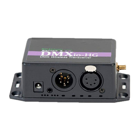
RC4 Wireless RC5 EASS IP65 Installation and operating manual

RC4 Wireless
RC5 EASS IP65
Installation Safety and
Site Preparation Guide
(c) 2018 RC4 Wireless. All rights reserved. Rev 1.1A

This document provides information you should carefully review and understand before installing
the RC4 Wireless RC5 EASS IP65 wireless DMX transceiver, including important safety
information, installation recommendations, site requirements, and specific installation steps.
These topics are discussed:
Safety Recommendations 4
Safety with Electricity 4
Preventing Electrostatic Discharge Damage 5
General Site Requirements 5
Mounting 5
Environmental Requirements 6
Power Guidelines and Requirements 6
Data Cabling 7
Antenna Positioning and Orientation 7
Required Tools and Equipment for Installation and Maintenance 7
What is Supplied 8
Optional Accessories (Not Included) 9
Main Power Connection 10
Data Cable Connection 11
Antenna Connection 12
Device Configuration 13
Automatic Transmit / Receive Functionality 14
Contact RC4 Wireless 14
Warning: Only trained and qualified personnel should be allowed to install, replace, or service this
equipment.
Warning: Ultimate disposal of this product should be handled according to all national laws and
regulations.
Warning: This unit might have more than one power supply connection. All connections must be
removed to de-energize the unit.
Warning: This product relies on the building’s installation for short-circuit (overcurrent) protection.
Ensure that the protective device is rated not greater than:
Maximum 15A, 120 VAC or Maximum 10A, 230 VAC.
Warning: Take care when connecting units to the supply circuit so that wiring is not overloaded.

Warning: Installation of the equipment must comply with local and national electrical codes.
Warning: This unit is intended for installation in restricted access areas. A restricted access area can
be accessed only through the use of a special tool, lock and key, or other means of security. The
enclosure of the device itself can be restricted with the addition of a suitable padlock (not included).
Warning: The RC5 enclosure prevents exposure to hazardous voltages and currents inside. Do not
operate the system unless all circuit boards, components, and covers are in place, and the enclosure
cover is closed and latched.
Warning: Read all installation instructions before connecting the system to the power source.
Warning: IMPORTANT SAFETY INSTRUCTIONS.
Before you work on any equipment, be aware of the
hazards involved with electrical circuitry and be familiar
with standard practices for preventing accidents.
SAVE THESE INSTRUCTIONS.

Safety Recommendations
Follow these guidelines to ensure general safety:
● Keep the chassis area clear and dust-free during and after installation.
● Keep tools and chassis components away from walk areas.
● Do not wear loose clothing that could get caught in the chassis.
● Fasten your tie or scarf and roll up your sleeves.
● Wear safety glasses when working under conditions that might be hazardous to your eyes.
● Do not perform any action that creates a hazard to people or makes the equipment unsafe.
Safety with Electricity
Follow these guidelines when working on equipment powered by electricity:
● Locate the emergency power-off switch in the room in which you are working.
● If an electrical accident occurs, you can quickly turn off the power.
● Disconnect all power before doing the following:
○ Installing or removing a chassis
○ Working near power supplies
● Look carefully for possible hazards in your work area, such as moist floors, ungrounded power
extension cables, frayed power cords, and missing safety grounds.
● Do not work alone if hazardous conditions exist.
● Never assume that power is disconnected from a circuit. Always check.
● Never open the enclosure of the built-in Class-2 power supply.
● If an electrical accident occurs, proceed as follows:
○ Use caution; do not become a victim yourself.
○ Turn off power to the device.
○ If possible, send another person to get medical aid. Otherwise, assess the victim’s condition
and then call for help.
○ Determine if the person needs rescue breathing or external cardiac compressions; then take
appropriate action.
Warning: Do not work on the system or connect or disconnect cables during periods of lightning
activity.

Preventing Electrostatic Discharge Damage
Electrostatic discharge (ESD) can damage equipment and impair electrical circuitry. It can occur if electronic
printed circuit cards are improperly handled and can cause complete or intermittent failures. Always follow
ESD prevention procedures when installing or making configuration changes using the buttons on the internal
circuit board.
● Ensure that metal-sheathed wiring is connected to earth ground and the power supply ground wire is
connected to the internal ground connection screw.
● Wear an ESD-preventive wrist strap, ensuring that it makes good skin contact.
● Connect the clip to grounded metal to channel unwanted ESD voltages safely to ground.
● To guard against ESD damage and shocks, the wrist strap and cord must operate effectively. If no
wrist strap is available, touch a metal part of the chassis to discharge any electromagnetic build up.
Caution: For the safety of your equipment, periodically check the resistance value of the antistatic
strap. It should be between 1 and 10 megohms (Mohm).
General Site Requirements
This section describes the requirements your site must meet for safe installation and operation of your RC4
Wireless transceiver. Ensure that the site is properly prepared before beginning installation. If you are
experiencing shutdowns or unusually high data errors with installed equipment, this section can also help you
isolate the cause of failures and prevent future problems.
Mounting
The transceiver is designed for mounting on a wall or pole. RC4 Wireless recommends that the transceiver
not be rack mounted.
The transceiver should be positioned with the RP-SMA antenna connector at the top, and the hinges for the
cover on the left.
The left side of the enclosure, behind the hinges, is equipped with right-angled IP65-rated ventilators. These
allow adequate air flow for cooling and help prevent condensation from forming inside. The open end of
these ventilators must be pointing downward, with the case hinges of the enclosure on the left.

Environmental Requirements
The location of your transceiver and the layout of the environment are important considerations for proper
operation. Equipment placed too close together, inadequate ventilation, and inaccessible enclosures can
cause malfunctions and shutdowns, and can make maintenance difficult.
Install the transceiver so that you can access both the bottom for power and data connections, and the top for
the antenna connection. Ensure that the enclosure door can be opened far enough for easy access to the
interior of the device.
If you are currently experiencing shutdowns or an unusually high number of data errors with your existing
equipment, these precautions and recommendations may help you isolate the cause of failure and prevent
future problems:
● Ensure that the location has adequate air circulation. Electrical equipment generates heat. Without
adequate air circulation, ambient air temperature may not cool equipment to acceptable operating
temperatures.
● Always follow ESD-prevention procedures described in the Preventing Electrostatic Discharge
Damage to avoid damage to equipment. Damage from static discharge can cause immediate or
intermittent equipment failure.
● Ensure that the chassis cover and cable glands are secure and water-tight.
● Ensure that the antenna is fully connected (finger tight is adequate) and the antenna connection is
free of moisture and debris.
DO NOT OVERTIGHTEN CABLE GLANDS. DO NOT OVERTIGHTEN THE ANTENNA.
Finger tight is adequate.
Power Guidelines and Requirements
Check the power at your site to ensure that you are receiving “clean” power (free of spikes and noise). Install
a power conditioner if necessary.
The RC5 EASS IP65 transceiver uses a fully isolated Class 2 power supply module. The class 2 power
supply is internationally safety certified* for AC voltage input within the range of 100VAC to 240VAC. No
manual selection of input voltage is required.
The NEMA enclosure for the RC5 EASS IP65 is non-conductive and poses no electric shock hazard when
fully closed and latched.
Warning: Enclosure must be closed when device is in use. Access must be controlled with a lock on
the chassis door, or access to the installation area must be controlled.
* Meanwell APV-12-12 Class 2 power supply is certified to UL8750, CSA C22.2 No.250.0-08, ENEC BIS
IS15885, EN61347-1, EN61347-2-13, EN62384 Independent, EAC TP TC 004 IP42 approved.

Data Cabling
Power supply ground is NOT connected to data ground within the RC5 EASS IP65 transceiver. A connection
screw for an AC power ground wire is provided, which affects only the area surrounding the power supply
section of the circuit board, outlined with white lines on the circuit board.
To avoid ground loops, particularly with long data cable distances, avoid connecting power and data ground
together at the transceiver. Allow the transceiver electronics to float to the ground potential of the data line.
DMX connections can be made via screw terminals or RJ45 connectors. Pin-out information is provided on
the circuit board, immediately adjacent to the connectors. The RJ45 pin-out complies with the ESTA standard
for DMX over RJ45.
To avoid data errors or data loss, low-capacitance cable must be used. Consult the following standards
for details on appropriate cable for DMX data transmission, and DMX over RJ45:
● USITT DMX512/1990 Digital Data Transmission Standard for Dimmers and Controllers
● ESTA / ANSI E1.11 - 2004 Asynchronous Serial Digital Data Transmission Standard for Controlling
Lighting Equipment and Accessories
Antenna Positioning and Orientation
RC5 transceivers should be positioned for the shortest possible distance between antennas with the fewest
obstacles in the line-of-sight path between antennas. Omnidirectional antennas, sometimes called whip
antennas, should be oriented vertically, with the tip pointing directly upward or downward. For other types of
antennas, follow instructions provided with them.
Higher elevation of antennas improves range. This is particularly true of the transmitter antenna.
When assembling a wireless DMX system consisting of multiple receivers, try to position the transmitter in the
center of the geographical service area, ensuring the shortest possible distances to all receivers. This is
preferred to placing the transmitter at one end of a line, or at the edge of a circle of devices. Nonetheless,
RC4 Wireless acknowledges that it is not always possible to position the transmitter centrally.
Required Tools and Equipment for Installation and Maintenance
You need the following tools and equipment to install an RC5 EASS IP65 transceiver:
● ESD-preventive cord and wrist strap.
● Electrical wiring tools commonly used by commercial electricians.
● Appropriate tools for mounting the enclosure to the wall material at the installation site.
Warning: Only trained and qualified personnel should be allowed to install, replace, or service
RC4 Wireless equipment and other devices connected to RC4 Wireless equipment.

What is Supplied
Each RC5 EASS IP65 device is shipped with:
● Main enclosure, which includes:
○ Main RC5 transceiver circuit board
○ Board-mounted internationally certified Class 2 power supply
○ RP-SMA antenna connection
○ 2-conductor Wago connector for AC power connections (pre-attached to internal
power supply input wires)
○ AC power cable gland, suitable for 5 - 11mm diameter cable
○ Data cable gland, suitable for 3 - 6mm diameter cable
● 900MHz omnidirectional dipole antenna, 19cm long, articulated base, RP-SMA connector
● Wall-mount kit consisting of 4 small brackets and screws

Optional Accessories (Not Included)
In most cases, RC5 transceivers can be mounted and connected without the need for additional
accessories.
It is recommended to use cable that fits within the diameter range of the provided glands.
Smaller cable sizes are NOT recommended and should be avoided. If a larger cable or conduit
must be accommodated, a larger gland can be installed by removing the existing gland, enlarging
the hole, and installing the replacement gland.
Caution: When enlarging gland holes, be sure to remove ALL resulting debris from the
RC5 EASS IP65 enclosure when done. Avoid contaminating the RC5 enclosure with metal
particles on drill bits and other tools.
The following are available at additional cost:
● Alternative antennas, including high-gain, directional, Yagi, panel, and more.*
● Antenna extension cables for mounting an antenna some distance from the RC5 enclosure.
● Pole mounting kits for RC5 EASS IP65 enclosures.
● Larger sizes of cable glands, for both power and data connections.
Caution: To ensure regulatory compliance, ONLY approved antennas may be used with RC5
EASS IP65 transceivers. A list of approved antennas is available from RC4 Wireless.

Main Power Connection
Warning: Only trained and qualified personnel should be allowed to install, replace, or service this
equipment.
Warning: Take care when connecting units to the supply circuit so that wiring is not overloaded.
Warning: Installation of the equipment must comply with local and national electrical codes.
Taking all appropriate safety precautions, bring supply wiring into the RC5 enclosure through the attached
cable gland at the bottom left of the enclosure. Power wiring must enter near the connection wires on the
internal Class 2 power supply.
Connect the incoming AC line and neutral wires to the line and neutral wires on the Class 2 power supply
using the provided Wago connector. Follow instructions and procedures provided by Wago for part number
222-412.
Keep internal AC wiring short and neat, without excess length within the RC5 EASS IP65 enclosure.
Cable-tie the incoming AC wiring to the Class 2 power supply wiring in a position that ensures the Wago
connector remains below the power supply, within the power wiring area outlined by white lines on the circuit
board.
Important: Remove only as much insulation as specified in instructions for Wago connectors,
typically 9 - 10mm. No bare wire should be visible when Wago connections are closed and complete.
If present, a ground or drain wire may be connected to the screw at the bottom center of the RC5 circuit
board. This screw is marked POWER GROUND. Grounding is not strictly required, because the enclosure is
non-conductive, the Class 2 power supply is fully isolated, and transceiver electronics are operating at 12VDC
and not more than 1A.

Data Cable Connection
Important: Ensure that data cabling is kept separate from AC power wiring and the two cannot come
in contact with each other.
Remove only as much sheathing and insulation from data cable conductors as needed to make connections
without difficulty. Ferrules are recommended for wires being inserted into screw terminals.
Observe markings on the circuit board for data conductor polarity. If using RJ45 connections, it may be
necessary to crimp the connector to the data cable after passing it through the cable gland.
There is no performance advantage to either the screw terminals or the RJ45 connectors. They are
connected in parallel. If passing DMX data through the RC5 to other devices, the input and output can be
either through screw terminals or RJ45 connectors. The connections can be used to convert from one to the
other, if need be.
Note: If the RC5 transceiver does not respond to incoming DMX data, the polarity of the data wiring
may be reversed. Swap the A/+ and B/- conductors.

Antenna Connection
WARNING! This equipment is FCC approved only for mobile and base
station transmitting devices. Antenna(s) used with this transceiver must
be installed to provide a separation distance of at least 34 cm from all
persons
and must not be co-located or operating in conjunction with any
other antenna or transmitter.
The RC5 EASS IP65 cannot be operated without an antenna attached to the RP-SMA connector at
the top of the enclosure.
Caution: ONLY approved 900MHz antennas may be used with RC5 EASS IP65 transceivers.
A list of appropriate antennas is available from RC4 Wireless.
Connect the provided antenna by threading the base of the antenna onto the connector on the top
of the enclosure.
FINGER TIGHT IS ADEQUATE. DO NOT OVERTIGHTEN THE ANTENNA.
Omnidirectional dipole antennas should be oriented in a vertical position, pointing upward. For
other types of antennas, observe and follow instructions provided for them. Antennas can be
extended using antenna cables. Consult RC4 Wireless for additional assistance.

Device Configuration
Important: RC4 Wireless provides all RC5 devices and systems fully
configured. Take care to NOT modify settings without specific intent.
Consult RC4 Wireless for assistance if needed.
RC4 Wireless RC5 transceivers utilize RC4 Wireless Private System IDs. Every system sold is programmed
with unique codes that are private to that system only. All devices within a given system must be
programmed with the same set of IDs, and the same specific ID must be selected within all devices that are to
communicate.
If devices are not operating as expected, it is often best to Restore Factory Defaults:
With the device powered on:
● Press and hold the Func button,
● Tap the ID3 / Set Defaults button,
● Release the Func button.
When the buttons are released, the left-most LEDs, yellow and green, will blink several times together,
followed by a device restart.
RC5 devices can be accessed and configured remotely, by wireless, using RC4 Commander software,
available for both PC and Mac. Software can be downloaded from:
https://www.rc4wireless.com/download/
Remote configuration requires an RC5 device to be connected to the computer running the software.
If you do not have an RC5 Dongle device and associated instructions, contact RC4 Wireless for additional
assistance.

Automatic Transmit / Receive Functionality
RC5 devices automatically assume transmitter or receiver functionality based on installation on context. If all
installation wiring is completed correctly, no further configuration is required. Simply power on all devices,
and they will operate as expected. They will wirelessly distribute DMX data from the source to one or more
destinations.
If wireless data that is encrypted with the correct RC4 Private System ID is present on the air, the transceiver
will behave as a wireless data receiver and output wired DMX data on the wired DMX connections.
Otherwise, if wired DMX data is present at the DMX data cable connections, the transceiver will behave as a
transmitter and broadcast wireless DMX data to receivers.
Contact RC4 Wireless
Your satisfaction is very important to us. Do not hesitate to contact us for assistance.
RC4 Wireless
13604 Heathwood Court
Raleigh, NC
USA 27615
http://www.rc4wireless.com
Toll-Free: 866-258-4577
Local: 919-229-9950
Specifications are subject to change without notice.
We have done our best to ensure accuracy, but we cannot
be responsible for errors or omissions.
Wireless DMX and Dimming.
RC4 Does That.™
Table of contents
Other RC4 Wireless Transceiver manuals