RCA ViSYS 25110 User manual

2.4 GHz Cordless Telephone
and Wireless Headset
with Call-Waiting/Caller ID
User’s Guide
Please read this manual before
operating this product for the first time. Model 25110
TM

2
Important Information
NOTICE: This product meets the applicable Industry Canada technical specifications.
Operation is subject to the following two conditions: (1) This device may not cause interference, and (2) This device must accept any
interference, including interference that may cause undesired operation of the device.
The equipment must be installed using an acceptable method of connection. The customer should be aware that compliance with the above
conditions may not prevent degradation of service in some situations.
Repairs to certified equipment should be made by an authorized Canadian maintenance facility designated by the supplier. Any repairs or
alterations made by the user to this equipment, or equipment malfunctions, may give the telecommunications company cause to request the
user to disconnect the equipment.
Users should ensure for their own protection that the electrical ground connections of the power utility, telephone lines and internal metallic
water pipe systems, if present, are connected together. This precaution may be particularly important in rural areas.
CAUTION: Users should not attempt to make such connections themselves, but should contact the appropriate electric inspection authority, or
electrician, as appropriate.
NOTES: This equipment may not be used on coin service provided by the telephone company.
REN NUMBER IS LOCATED ONTHE CABINET BOTTOM
Important Information

3
Interference Information
This equipment generates and uses radio frequency energy which may interfere with residential radio and television reception if not
properly installed and used in accordance with instructions contained in this manual. Reasonable protection against such interference is
ensured, although there is no guarantee this will not occur in a given installation. If interference is suspected and verified by switching
this equipment on and off, the user is encouraged to try to correct the interference by one or more of the following measures: Reorient
the radio/television receiver’s antenna, relocate the equipment with respect to the receiver, plug the equipment and receiver into separate
circuit outlets. The user may also wish to consult a qualified radio/television technician for additional suggestions. This equipment has been
fully tested and complies with all limits for Class B computing devices pursuant to part 15 FCC Rules and Regulations.
Hearing Aid Compatibility
This telephone system meets FCC standards for Hearing Aid Compatibility.
Licensing
Licensed under US Patent 6,427,009.
Important Information

4
Table of Contents
Important InformatIon ................................................................. 2
Interference InformatIon.............................................................. 3
HearIng aId compatIbIlIty ............................................................ 3
lIcensIng ..................................................................................... 3
IntroductIon ................................................................................ 6
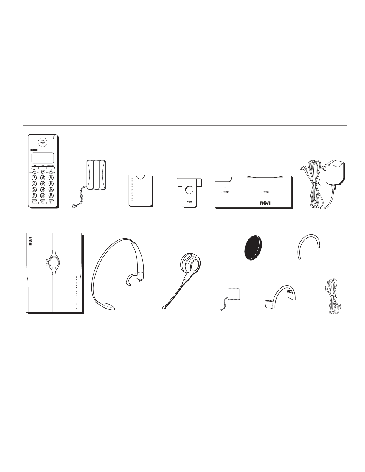
parts cHecklIst............................................................................ 7
Important InstallatIon InformatIon............................................... 8
Safety PrecautionS..................................................................................8
inStallation GuidelineS ...........................................................................8
telepHone Jack requIrements........................................................ 9
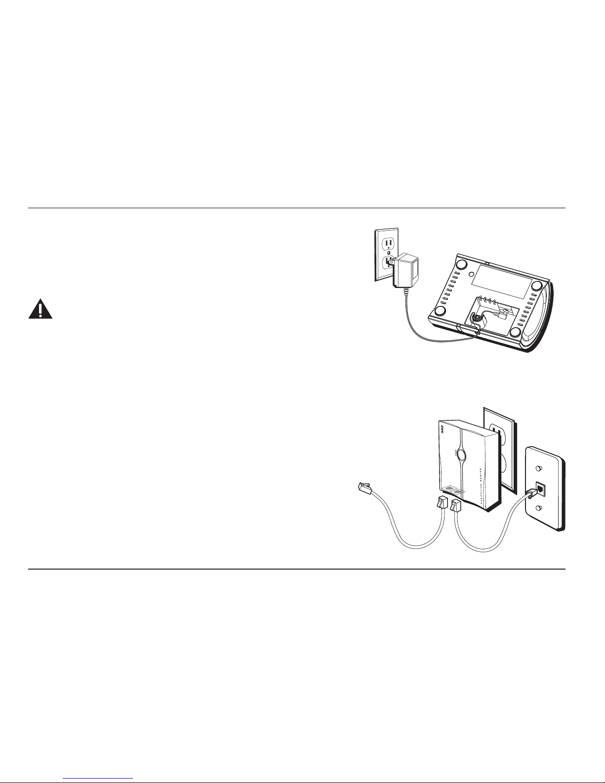
pHone InstallatIon..................................................................... 10
connectinG the ac (electrical) Power.............................................. 10
Charger unit............................................................................................. 10
Wall base unit ......................................................................................... 10
connectinG the telePhone line............................................................ 10
inStallinG the BatterieS ........................................................................11
Installing the Handset Battery............................................................11
Installing the Headset Battery...........................................................12
Headset set up.......................................................................... 13
headBand attachment ......................................................................... 13
To switch from ear to ear....................................................................14
ear cliP attachment............................................................................ 15
To switch from ear to ear....................................................................15
Handset layout ......................................................................... 16
Headset layout.......................................................................... 17
Handset set up......................................................................... 18
diSPlay lanGuaGe ................................................................................. 18
tone/PulSe dialinG .............................................................................. 18
area code............................................................................................. 18
rinGer tone.......................................................................................... 19
rinGer Volume ..................................................................................... 19
default SettinG Selection.................................................................... 19
telepHone operatIon .................................................................. 20
makinG acall...................................................................................... 20
On the Handset.......................................................................................20
On the Headset.......................................................................................20
anSwerinG a call................................................................................ 20
On the Handset...........................................................................20
On the Headset...........................................................................20
call tranSfer ....................................................................................... 21
mute ..................................................................................................... 21
redial.................................................................................................... 21
flaSh..................................................................................................... 22
exit........................................................................................................ 22
handSet Volume................................................................................... 22
headSet Volume ................................................................................... 22
To Adjust Volume from Headset:.......................................................22
To Adjust Volume from Handset:......................................................22

5
Table of Contents
PaGinG the handSet and headSet........................................................ 23
inuSe indicator liGht ......................................................................... 23
On the Handset.......................................................................................23
On the Headset.......................................................................................23
charGer indicator liGht...................................................................... 23
call timer ............................................................................................ 24
temPorary tone dialinG ...................................................................... 24
caller Id .................................................................................. 25
caller id with call waitinG .............................................................. 25
receiVinG and StorinG callS ............................................................... 25
reViewinG recordS............................................................................... 25
tranSferrinG cid recordS to memory .............................................. 26
deletinG recordS ................................................................................. 26
deletinG the current record.............................................................. 26
deletinG all recordS........................................................................... 27
dialinG acaller id numBer ............................................................... 27
chanGinG the cid numBer format .................................................... 27
memory .................................................................................... 28
StorinG aname and numBer in memory........................................... 28
ViewinG aStored numBer ................................................................... 29
chanGinG aStored numBer ................................................................ 29
StorinG aredial numBer .................................................................... 29
dialinG aStored numBer.................................................................... 30
inSertinG aPauSe in the dialinG Sequence of aStored numBer...... 30
reViewinG and deletinG Stored numBerS........................................... 30
Headset and belt clIp operatIon ................................................ 31
connectinG an oPtional headSet to the handSet.............................. 31
attachinG the Belt cliP ....................................................................... 31
replacIng tHe batterIes .............................................................. 32
handSet Battery................................................................................... 32
handSet memory retention ............................................................... 32
headSet Battery ................................................................................... 33
battery safety precautIons ........................................................ 33
dIsplay messages ...................................................................... 34
Handset sound sIgnals.............................................................. 35
caller id.............................................................................................. 36
No display.................................................................................................36
Caller ID error message........................................................................36
telePhone.............................................................................................. 36
No dial tone.................................................................................36
troublesHootIng tIps.................................................................. 37
general product care ............................................................... 38
causes of poor receptIon .......................................................... 38
telepHone network InformatIon ................................................. 39
ren number............................................................................. 40
servIce ...................................................................................... 41
accessory InformatIon............................................................... 43

6
SEE MARKING ON BOTTOM / BACK OF PRODUCT
RISKOFELECTRICSHOCK
DONOTOPEN
WARNING: TO
PREVENT FIRE OR
ELECTRICAL SHOCK
HAZARD, DO NOT
EXPOSETHIS
PRODUCT TO RAIN
OR MOISTURE.
THE LIGHTNING
FLASH AND ARROW
HEAD WITHIN THE
TRIANGLE IS A
WARNING SIGN
ALERTING YOU OF
“DANGEROUS
VOLTAGE” INSIDE
THE PRODUCT.
CAUTION: TO REDUCE THE
RISK OF ELECTRIC SHOCK, DO
NOT REMOVE COVER (OR
BACK). NO USER
SERVICEABLE PARTS INSIDE.
REFER SERVICING TO
QUALIFIED SERVICE
PERSONNEL.
THE EXCLAMATION
POINT WITHIN THE
TRIANGLE IS A
WARNING SIGN
ALERTING YOU OF
IMPORTANT
INSTRUCTIONS
ACCOMPANYING
THE PRODUCT.
CAUTION:
Important Information
Introduction
CAUTION: When using telephone equipment, there are basic safety instructions that
should always be followed. Refer to the IMPORTANT SAFETY INSTRUCTIONS provided
with this product and save them for future reference.
Your Caller ID phone stores and displays information provided by your local
telephone company, to subscribers of Caller ID or similar caller identification
services.
Your Caller ID phone enables you to:
• Identify callers before you answer the phone.
• View the time and date of each incoming call.
• Record up to 99 Caller ID messages sequentially.
• Know who called while you were away.
To get the most from your new phone, we suggest that you take a few minutes
right now to read through this user’s guide.
IMPORTANT: In order to use all of the features of this unit, you must subscribe to either the
standard Name/Number Caller ID Service or Call Waiting Caller ID Service. To know who is
calling while you are on the phone, you must subscribe to Call Waiting Caller ID Service.
IMPORTANT: Because cordless phones operate on electricity, you should have at least one
phone in your home that isn’t cordless, in case the power in your home goes out.

7
Parts Checklist
Make sure your package includes the following items:
Wall base
Handset Battery
compartment cover
Telephone
line cord
AC power
adaptor
Connections & Setup
ChargerHandset battery Belt clip
Headband Headset battery Ear clip ring
Ear clip
Headset
Headset sponge
cover

8
Important Installation Information
Safety Precautions
• Never install telephone wiring during a lightning storm.
• Never install telephone jacks in wet locations unless the jack is specifically
designed for wet locations.
• Never touch non-insulated telephone wires or terminals, unless the telephone
line is disconnected from the network.
• Use caution when installing or modifying telephone lines.
• Temporarily disconnect any equipment connected to the phone such as faxes,
other phones, or modems.
Installation Guidelines
• Install the wall base unit into an electrical outlet that is near a telephone
(modular) jack.
• Avoid sources of noise, such as a window by a busy street, and electrical noise,
such as motors, microwave ovens, and fluorescent lighting.
• Avoid heat sources, such as heating air ducts, heating appliances, radiators, and
direct sunlight.
• Avoid areas of excessive moisture or extremely low temperature.
• Avoid dusty locations.
• Avoid other cordless telephones or personal computers.
Connections & Setup

9
Modular telephone
line jack
Wall plate
Connections & Setup
CAUTION: Always disconnect all phone cords from the base unit before battery
installation or replacement.
INSTALLATION NOTE: Some cordless telephones operate at frequencies that may cause
or receive interference with TVs, microwave ovens, and VCRs. To minimize or prevent such
interference, the base of the cordless telephone should not be placed near or on top of a TV,
microwave ovens, or VCR. If such interference continues, move the cordless telephone farther
away from these appliances. Certain other communications devices may also use the 2.4GHz
frequency for communication, and, if not properly set, these devices may interfere with each
other and/or your new telephone. If you are concerned with interference, please refer to
the owner’s manual for these devices on how to properly set channels to avoid interference.
Typical devices that may use the 2.4GHz frequency for communication include wireless
audio/video senders, wireless computer networks, multi-handset cordless telephone systems,
and some long-range cordless telephone systems.
Telephone Jack Requirements
To use this phone, you will need an RJ11C type modular phone jack, which might
look like the one pictured here, installed in your home. If you don’t have a modular
jack, call your local phone company to find out how to get one installed.

10
Phone Installation
Connecting the AC (Electrical) Power
Charger unit
Plug the AC power adaptor into an electrical outlet and the DC connector into the
bottom of the charger.
CAUTION: Only use the 5-2745 power adaptor that came with this unit. Using other
power adaptors may damage the charger unit.
Wall base unit
To install your wall base unit, locate an electrical outlet with a phone jack nearby.
1. Plug the wall base unit into an electrical outlet.
2. Make sure that the pins are inserted fully and firmly into the outlet. If not,
choose another electrical outlet.
Connecting the Telephone Line
There are two jacks on the bottom of the wall base unit.
Plug one end of the telephone line cord into the LINE jack on the bottom of the
wall base unit and the other end into a modular jack.
The PHONE jack may be used to connect a parallel phone by connecting a second
telephone line cord from the PHONE jack on the bottom of the wall base unit to the
parallel phone.
Connections & Setup

11
Installing the Batteries
Installing the Handset Battery
CAUTION: To reduce the risk of fire or personal injury, only use the Thomson Inc.
approved Ni-MH battery model 5-2683.
NOTE: You must connect the handset battery before use.
1. Locate battery and battery door which are packaged together inside a plastic
bag and are separated from the handset.
2. Locate the battery compartment on the back of the handset.
3. Plug the battery pack cord into the jack inside the compartment.
NOTE: It is important to maintain the polarity (black and red wires) to the jack inside the
compartment. To ensure proper battery installation, the connector is keyed and can be
inserted only one way.
4. Insert the battery pack.
5. Close the battery compartment by pushing the door up until it snaps into place.
6. Place the handset in the charging cradle.
Allow the handset to charge for 16 hours prior to first use. If you don’t properly charge the
handset, battery performance is compromised.
Connections & Setup
BLACK WIRE
RED
W
IRE
BATTERY
PRESS DOWN
FIRMLY

12
Installing the Headset Battery
CAUTION: To reduce the risk of fire or personal injury, only use Thomson Inc. approved
Li-polymer battery model 5-2707.
NOTE: You must connect the headset battery before use.
1. Locate battery which is packaged inside a plastic bag and separate from the
headset.
2. Open the battery compartment door on the headset.
3. Insert the battery pack.
4. Plug the battery pack cord into the jack inside the compartment.
NOTE: It is important to maintain the polarity (black and red wires) to the jack inside the
compartment. To ensure proper battery installation, the connector is keyed and can be
inserted only one way.
5. Close the battery compartment by pushing the door up until it snaps into place.
6. Attach the foam cover.
7. Place the headset in the charging cradle.
Allow the headset to charge for 16 hours prior to first use. If you don’t properly charge the
headset, battery performance is compromised.
Connections & Setup

13
Headset Set Up
Headband Attachment
1. Hold the headband and insert it into keyed slot marked with an arrow on the
headset.
NOTE: To ensure proper installation, the connector is keyed and can only be inserted one way
2. Rotate the L-shaped band 90 degrees clockwise.
3. Align the L-shaped band into the hole on the headset.
Connections & Setup

14
To switch from ear to ear
Rotate microphone boom to reposition nearer to mouth.
Connections & Setup

15
Ear Clip Attachment
1. Attach the ear clip ring to the headset and ensure all three contact points align
and are engaged.
Connections & Setup
2. Insert ear clip into either side of ear clip ring, matching with the L or R marked
on ear clip ring to fit either your left or right ear.
To switch from ear to ear
Unplug the ear clip from ear clip ring.
Insert the ear clip to ear clip ring with L mark for Left ear.
Insert the ear clip to R mark for Right ear.
Rotate microphone boom to reposition nearer to mouth.

16
CID/Vol 6
(Caller ID/Volume
button)
Redial/Format
(button)
Talk
(button)
Prog/Flash
(program/flash
button)
*Exit
(button)
Mem
(memory button)
#Pause
(button)
display
Off
(button)
Handset Layout
Mute/Del
(mute/delete
button)
CID/Vol 5
(Caller ID/Volume
button)
Headset
(button)
VM
(Voicemail
indicator)
Connections & Setup

17
Vol 3or 4
(Volume button)
Charge
indicator
Talk/Off
(button)
Headset Layout
Connections & Setup
Charge
contact

18
Handset Set Up
There are six programmable menus available: Display Language, Tone/Pulse
Dialing, Local Area Code, Ringer Tone, Ringer Volume and Factory Default.
When you program these settings, make sure the phone is OFF (not in talk mode).
Pressing the *Exit button will remove you from the menu selection process without
changing the feature you are in.
Display Language
1. Press the Prog/Flash button until 1ENG 2FRA 3ESP shows in the display.
2. Use the CID/Vol ( 5or 6) buttons or the handset number pad to select
1.ENGLISH, 2.FRANCAIS, or 3.ESPANOL. The default setting is 1ENG.
3. Press the Prog/Flash button to confirm. You will hear a confirmation tone.
Tone/Pulse Dialing
1. Press the Prog/Flash button until 1TONE 2PULSE shows in the display.
2. Use the CID/Vol ( 5or 6) buttons or the handset number pad to select
(1) TONE or (2) PULSE. The default setting is TONE.
3. Press the Prog/Flash button to confirm. You will hear a confirmation tone.
Area Code
1. Press the Prog/Flash button until - - - SET AREA CODE shows in the display.
2. Use the handset touch-tone pad to enter your three digit area code. - - - is the
default setting.
3. Press the Prog/Flash button to confirm. You will hear a confirmation tone.
Connections & Setup

19
Ringer Tone
1. Press the Prog/Flash button until RINGER TONE 1 shows in the display.
2. Use the CID/Vol ( 5or 6) buttons or the handset number pad to select
and listen to a ringer tone. There are seven ringer tones to choose from. The
default setting is 1.
3. Press the Prog/Flash button to confirm. You will hear a confirmation tone.
Ringer Volume
1. Press the Prog/Flash button until RINGER VOL 1HI shows in the display.
2. Use the CID/Vol ( 5or 6) buttons or the handset number pad to select 1 (HI),
2 (LOW), or 3 (OFF). The default setting is 1HI.
3. Press the Prog/Flash button to confirm. You will hear a confirmation tone.
Default Setting Selection
1. Press the Prog/Flash button until DEFAULT 41NO shows in the display.
2. Use the CID/Vol ( 5or 6) buttons or the handset number pad to select 1 (NO),
or 2 (YES). The default setting is 41NO. If you choose NO, the current settings
remain. If you choose YES, the unit resets to the factory defaults.
3. Press the Prog/Flash button to confirm.
Connections & Setup

20
Telephone Operation
Making a Call
On the Handset
1. Press the Talk button on the handset to get a dial tone.
2. When finished, press the Off button on the handset to hang up.
On the Headset
1. Press the Talk/Off button on the headset OR the Headset button on the handset
to get a dial tone.
2. When finished, press the Off button on the handset OR the Talk/Off button on
the headset to hang up.
Answering A Call
On the Handset
1. When the phone rings, pick up the handset and press the Talk button to answer
the call.
2. When finished, press Off button on the handset to hang up.
On the Headset
1. When the phone rings, pick up the headset and press the Talk/Off button OR
press the Headset button on the handset to answer the call.
2. When finished, press the Talk/Off button on the headset OR the Off button on
the handset to hang up.
Operation
Other manuals for ViSYS 25110
1
Table of contents
Languages:
Other RCA Cordless Telephone manuals

RCA
RCA 27928 User manual

RCA
RCA 7114-2BSGA User manual

RCA
RCA 25420 User manual

RCA
RCA TC25211 User manual

RCA
RCA 25255RE2 - ViSYS Cordless Phone Base Station User manual

RCA
RCA Visys 25250RE1 User manual

RCA
RCA 2132 User manual

RCA
RCA 25211 User manual

RCA
RCA 2101-2 User manual

RCA
RCA DECT 00023265 User manual