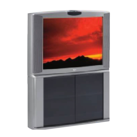
RCA Scenium PHD50500 User manual

PHD50500 Plasma Monitor User’s Guide

ii
Safety Precautions
IMPORTANT NOTICE
The serial number for this equipment is located on the rear
panel. Please write this serial number on your enclosed
warranty card and keep it in a secure area. This is for your
security.
The following symbols are found on labels
attached to the product. They alert the operators
and service personnel of this equipment to any
potentially dangerous conditions.
WARNING
This symbol refers to a hazard or unsafe
practice which can result in personal injury
or property damage.
CAUTION
This symbol refers to a hazard or unsafe
practice which can result in severe personal
injury or death.
i
CAUTION: WHEN POSITIONING THIS EQUIPMENT
ENSURE THAT THE MAINS PLUG AND SOCKET IS EASILY
ACCESSIBLE.
Product Registration
Please fill out the product registration card (packed separately) and return it immediately. For U.S. customers: Your RCA
Scenium Consumer Electronics product may also be registered at www.rcascenium.com/productregistration. Registering this
product allows us to contact you if needed.
Product Information
Keep your sales receipt to obtain warranty parts and service and for proof of purchase. Attach it here and record the serial and
model numbers in case you need them. The numbers are located on the back of the product.
Model No. _____________________________________________________________________
Serial No. ______________________________________________________________________
Purchase Date: _________________________________________________________________
Dealer/Address/Phone: __________________________________________________________

iii
Safety Precautions
Safety Precautions
GROUNDING OR POLARIZATION
÷If this product is equipped with a polarized
alternating current line plug (a plug having one
blade wider than the other), it will fit into the outlet
only one way. This is a safety feature. If you are
unable to insert the plug fully into the outlet, try
reversing the plug. If the plug should still fail to fit,
contact your electrician to replace your obsolete
outlet. Do not defeat the safety purpose of the
polarized plug.
÷If this product is equipped with a three-wire
grounding type plug, a plug having a third
(grounding) pin, it will only fit into a grounding type
power outlet. This is a safety feature. If you are
unable to insert the plug into the outlet, contact
your electrician to replace your obsolete outlet. Do
not defeat the safety purpose of the grounding
type plug.
POWER-CORD PROTECTION — Power-supply cords
should be routed so that they are not likely to be
walked on or pinched by items placed upon or
against them, paying particular attention to cords
at plugs, convenience receptacles, and the point
where they exit from the product.
OUTDOOR ANTENNA GROUNDING — If an outside
antenna or cable system is connected to the
product, be sure the antenna or cable system is
grounded so as to provide some protection against
voltage surges and built-up static charges. Article
810 of the National Electrical Code, ANSI/NFPA
70, provides information with regard to proper
grounding of the mast and supporting structure,
grounding of the lead-in wire to an antenna
discharge unit, size of grounding conductors,
location of antenna-discharge unit, connection to
grounding electrodes, and requirements for the
grounding electrode. See Figure A.
LIGHTNING — For added protection for this product
during a lightning storm, or when it is left
unattended and unused for long periods of time,
unplug it from the wall outlet and disconnect the
antenna or cable system. This will prevent damage
to the product due to lightning and power-line
surges.
POWER LINES — An outside antenna system should
not be located in the vicinity of overhead power
lines or other electric light or power circuits, or
where it can fall into such power lines or circuits.
When installing an outside antenna system,
extreme care should be taken to keep from
touching such power lines or circuits as contact
with them might be fatal.
OVERLOADING — Do not overload wall outlets,
extension cords, or integral convenience
receptacles as this can result in a risk of fire or
electric shock.
IMPORTANT SAFETY INSTRUCTIONS
READ INSTRUCTIONS — All the safety and operating
instructions should be read before the product is
operated.
RETAIN INSTRUCTIONS — The safety and operating
instructions should be retained for future
reference.
HEED WARNINGS — All warnings on the product and
in the operating instructions should be adhered to.
FOLLOW INSTRUCTIONS — All operating and use
instructions should be followed.
CLEANING — Unplug this product from the wall outlet
before cleaning. The product should be cleaned
only with a polishing cloth or a soft dry cloth. Never
clean with furniture wax, benzine, insecticides or
other volatile liquids since they may corrode the
cabinet.
ATTACHMENTS — Do not use attachments not
recommended by the product manufacturer as
they may cause hazards.
WATER AND MOISTURE — Do not use this product
near water — for example, near a bathtub, wash
bowl, kitchen sink, or laundry tub; in a wet
basement; or near a swimming pool; and the like.
ACCESSORIES — Do not place this product on an
unstable cart, stand, tripod, bracket, or table. The
product may fall, causing serious injury to a child
or adult, and serious damage to the product. Use
only with a cart, stand, tripod, bracket, or table
recommended by the manufacturer, or sold with
the product. Any mounting of the product should
follow the manufacturer’s instructions, and should
use a mounting accessory recommended by the
manufacturer.
CART — A product and cart combination should be
moved with care. Quick stops, excessive force,
and uneven surfaces may cause the product and
cart combination to overturn.
VENTILATION — Slots and openings in the cabinet
are provided for ventilation and to ensure reliable
operation of the product and to protect it from
overheating, and these openings must not be
blocked or covered. The openings should never
be blocked by placing the product on a bed, sofa,
rug, or other similar surface. This product should
not be placed in a built-in installation such as a
bookcase or rack unless proper ventilation is
provided or the manufacturer’s instructions have
been adhered to.
POWER SOURCES — This product should be operated
only from the type of power source indicated on
the marking label. If you are not sure of the type
of power supply to your home, consult your
product dealer or local power company.
LOCATION — The appliance should be installed in a
stable location.
NONUSE PERIODS — The power cord of the
appliance should be unplugged from the outlet
when left unused for a long period of time.
OBJECT AND LIQUID ENTRY — Never push objects
of any kind into this product through openings as
they may touch dangerous voltage points or short-
out parts that could result in a fire or electric shock.
Never spill liquid of any kind on the product.
SERVICING — Do not attempt to service this product
yourself as opening or removing covers may
expose you to dangerous voltage or other hazards.
Refer all servicing to qualified service personnel.
DAMAGE REQUIRING SERVICE — Unplug this
product from the wall outlet and refer servicing to
qualified service personnel under the following
conditions:
÷When the power-supply cord or plug is damaged.
÷If liquid has been spilled, or objects have fallen
into the product.
÷If the product has been exposed to rain or water.
÷If the product does not operate normally by
following the operating instructions. Adjust only
those controls that are covered by the operating
instructions as an improper adjustment of other
controls may result in damage and will often
require extensive work by a qualified technician to
restore the product to its normal operation.
÷If the product has been dropped or damaged in
any way.
÷When the product exhibits a distinct change in
performance — this indicates a need for service.
REPLACEMENT PARTS — When replacement parts
are required, be sure the service technician has
used replacement parts specified by the
manufacturer or have the same characteristics as
the original part. Unauthorized substitutions may
result in fire, electric shock, or other hazards.
SAFETY CHECK — Upon completion of any service
or repairs to this product, ask the service technician
to perform safety checks to determine that the
product is in proper operating condition.
HEAT — The product should be situated away from
heat sources such as radiators, heat registers,
stoves, or other products (including amplifiers) that
produce heat.
WALL OR CEILING MOUNTING — The product
should be mounted to a wall or ceiling only as
recommended by the manufacturer.
ANTENNA
LEAD IN
WIRE
GROUND
CLAMP
ELECTRIC
SERVICE
EQUIPMENT
ANTENNA
DISCHARGE UNIT
(NEC SECTION 810-20)
GROUNDING CONDUCTORS
(NEC SECTION 810-21)
GROUND CLAMPS
POWER SERVICE GROUNDING
ELECTRODE SYSTEM
(NEC ART 250, PART H)
Figure A
NEC – NATIONAL ELECTRICAL CODE
ii
This page intentionally left blank.

1
Table of Contents
Before Proceeding
How to Use This Manual .................. 2
How to Use the Menus ....................................... 4
Checking Supplied Parts .................. 4
Part Names and Functions
Main Unit ........................................... 5
Connection Panel .............................. 6
A Quick Tour of the Remote Control
The Remote Control.......................... 8
Button Descriptions for Monitor Mode ............. 8
Button Descriptions for Other Components ..... 9
Using Your Remote Control ............................. 10
Programming the Remote................................ 10
Find Out if You Need to Program the
Remote ........................................................... 10
How to Program the Remote ........................... 11
How to Use the Remote Control After
You’ve Programmed It .................................. 12
Programmable Codes for
the Remote Control ..................... 13
Installation and Connections
Installation of the Unit.................... 15
About the Input Connectors
on this Unit .................................. 16
Connection to INPUT1 and
INPUT2 ......................................... 16
Connection to AV Components ....................... 16
Connection to a Personal Computer ............... 18
Connection to INPUT3 .................... 20
Connection to INPUT5 .................... 20
Connection to INPUT4 .................... 20
About HDTV Set Top Box
Connection ................................... 21
Audio Connections .......................... 22
Power Cord Connection ................. 24
Setting Up the System
Setup after Connection .................. 25
Setting the Screen Mode/ Input Signal
Format ............................................................ 25
CLAMP POSITION Setup .................................. 26
Operations
Selecting an Input Source .............. 27
To Adjust the Volume ....................................... 28
To Mute the Sound ........................................... 28
To Confirm Display Settings ............................ 28
Screen Size Selection ..................... 29
Changing the Screen Size ................................ 29
Moving the Screen Position Upward or
Downward ...................................................... 29
Automatic Screen Size ..................................... 29
Partial Image Enlargement
(Zoom) ......................................... 30
Automatic Power OFF .................... 31
Monitor Panel Adjustments
Adjusting the Picture Quality......... 32
Monitor Panel Adjustments ........... 32
Adjusting the Image Position
and Clock (Automatic
Adjustment) ................................. 33
Manual Adjustment of Screen
Position and Clock ....................... 33
Other Operations
Changing the Color Temperature
(COLOR TEMP) ............................. 35
Reducing Video Noise
(DIGITAL NR) ................................ 35
Setting the Film Mode .................... 36
Viewing a Fast Moving Picture
(3D Y/C MODE) ............................ 36
Viewing in a Bright Location
(HIGH CONTRAST) ...................... 37

2
Table of Contents
Audio Output (AUDIO OUT) ........... 38
Setting the Menu Language .......... 38
Additional Information
Cleaning ......................................... 39
Troubleshooting .............................. 40
Additional Notes and Cautions...... 43
Specifications .................................. 44
Supplement 1 .................................. 45
Supplement 2 .................................. 46
Supplement 3 .................................. 47
Supplement 4 .................................. 47
Explanation of Terms ...................... 47
Limited Warranty ............................ 48
FCC Declaration of Conformity
and Industry Canada
Information .................................. 50

3
Before Proceeding
How to Use This Manual
This manual is set up to follow the course of actions and
operations in the order that would seem most logical for
someone setting up this unit.
Once the unit has been taken out of the box, and it has
been confirmed that all the parts have been received, it
may be beneficial to look over the section “Part Names
and Functions” starting on page 5 to become acquainted
with the plasma monitor and remote control unit, as their
respective buttons and controls will be referred to
throughout this manual.
The section “Installation and Connections” starting on
page 15 covers all the necessary points regarding
installation of the plasma monitor and connections to a
wide variety of components.
The section “Setting Up the System” starting on page 25
covers the necessary on-screen menu settings to
establish correct linkage between the plasma monitor and
connected components. Depending on the connections
made, this section may or not be necessary.
The remainder of the sections in this manual is dedicated
to the basic operations associated with selecting a source
component up to the more complex operations
associated with adjusting the plasma monitor picture to
match the requirements of specific components and
personal preferences.
About operations in this manual
Operations in this manual are outlined in step by step
numbered procedures. Most of the procedures are
written in reference to the remote control unit unless the
button or control is only present on the main unit.
However, if a button or control on the main unit has the
same or similar name as that on the remote control unit,
that button can be used when performing operations.
Note
The screen displays depicted in this manual represent typical
display examples.
The actual items and contents seen in screen displays may vary
depending on input source and specific settings.
Apple and Macintosh are registered trademarks of Apple Computer, Inc.
Microsoft is a registered trademark of Microsoft Corporation.
NEC and PC-9800 are trademarks of NEC Corporation.
VESA and DDC are registered trademarks of Video Electronics Standards Association.
Power Management and Sun Microsystems are registered trademarks of Sun Microsystems, Inc.
VGA and XGA are registered trademarks of International Business Machines Co., Inc.

4
Checking Supplied Parts
Check that the following parts were supplied.
1Power cord
2Remote control
3AA (R6) batteries ( x 2)
4Stereo mini to RCA plugs cable
5BNC to RCA phono jack adapters ( x 5)
(may be attached to the back of the monitor)
Before Proceeding
How to Use the Menus
The following example is an actual operation that shows how
you might set the horizontal and vertical positions of the
screen. The screens shown at each step are provided as a
visual guide to confirm that the procedure is proceeding as it
should. Please familiarize yourself with this process before
continuing with the rest of this manual.
1Press MENU to display the menu screen.
MAIN MENU INPUT1
SELECT ENTER EXIT
OK
CLEAR
RSETE
:
0
CONT RA ST :
0
BRIGHTNESS :
0
CO LOR
:
0
TINT :
0
SHARPNESS
PICTURE SET UP OPTION
2Press to select SCREEN.
:
00
POS I T I ON
CL OC HAS EK/ /
:
00
/
P
RSETE
MAIN MENU INPUT1
SELECT ENTER EXIT
OK
CLEAR
PICTURE SCREEN SET UP OPTION
3Press / to select the item to be adjusted.
:
00
POS I T I ON
CL OC HAS EK/ /
:
00
/
P
RSETE
MAIN MENU INPUT1
SELECT ENTER EXIT
OK
CLEAR
PICTURE SCREEN SET UP OPTION
4Press OK to display the adjustment screen for the
selected item.
ADJUS
T
SE
T
EXI
T
O
K
C
L
EAR
POH. S I T I ON :
0
POV. S I T I ON :
0
5Press / / / to adjust the value.
STOP PAUSE
MONITOR
ON•OFF
AUX
DVD SAT•CABLE
RECORD
PLAYFOR
WARDREVERSE
AUTO SET
CINEMA
MUTE
INFO
MENU
OK
CLEAR
GUIDE
ANTENNA
123
456
789
0
INPUT
VCR
1
A
VCR
2
C
H
+
C
H
–
V
O
L
V
O
L
GO BACK
REPEAT AUDIO ANGLE OPEN
Z
O
O
M
u n i v e r s a l
DVD

5
Part Names and Functions
Main Unit
Front of the Plasma Monitor
1STANDBY/ON indicator
This indicator is red during standby mode, and turns
to green when the unit is in the operation mode
(page 27).
Flashes green when Power-Management function is
operating (page 31).
The flashing pattern is also used to indicate error
messages (page 43).
2POWER button
Turns plasma monitor on and off.
3INPUT button
Press to select input (page 27).
4CINEMA button
Press to select the screen size (page 29).
5VOLUME –/+ buttons
Press to adjust the volume.
6Remote control sensor
Point the remote control toward the remote sensor to
operate the unit (page 10)
Main unit
Operation panel on the main unit
– VOLUME +
CINEMA
INPUT
POWER
STANDBY/ON
1
POWER
POWER
3
4
56
2
INPUT
INPUT
CINEMA
CINEMA
–
–
VOLUME
VOLUME
+
+

6
6Synchronizing signal impedance selector switch
Depending on the connections made at INPUT2, it
may be necessary to set this switch to match the
output impedance of the connected component’s
synchronization signal.
When the output impedance of the component’s
synchronization signal is 75 Ω, set this switch to the
75 Ωposition (pages 17-19).
7AUDIO INPUT (Stereo mini jack)
Use to obtain sound when INPUT1 or INPUT2 is
selected.
Connect the audio output terminal of components
connected to INPUT1 or INPUT2 (page 22).
8AUDIO OUTPUT (Stereo mini jack)
Use to output the audio of the selected source
component connected to this unit to an AV amplifier
or similar component (page 22). Use the supplied
stereo mini to RCA phono plugs cable.
9DVI VIDEO INPUT5 (DVI jack)
For connection of components that have a DVI digital
video output terminal such as a video camera,
LaserDisc player, or DVD player (page 20).
0AUDIO INPUT5 (RCA Pin jacks)
Use to obtain sound when INPUT5 is selected.
Connect these jacks to the audio output connectors of
components connected to INPUT5 (page 23).
Note: The left audio channel (L) jack is not compatible with
monaural input sources.
Part Names and Functions
Connection Panel
The connection panel has five video input terminals and
one video output terminal. Audio input and speaker
output terminals are also provided.
For instructions regarding connections, consult the pages
noted in parentheses by each item.
1SPEAKER (R) terminal
For connecting an external right speaker.
Connect a speaker whose impedance is 8 –16 Ω
(page 22).
2UPGRADE PORT
DO NOT MAKE ANY CONNECTIONS TO THIS
TERMINAL.
This terminal is used in the factory setup.
3INPUT1 (mini D-sub 15 pin)
For connection of components that have RGB or
component output jacks such as a personal
computer, HD receiver, DVD player, or external RGB
decoder. Make sure that the connection made
corresponds to the format of the signal output from
the connected component (pages 16-19).
4OUTPUT (INPUT1) (mini D-sub 15 pin)
Use the OUTPUT (INPUT1) terminal to output the
video signal to an external monitor or other
component.
Note: The video signal will not be output from the OUTPUT
(INPUT1) terminal when the main power of this unit is off or in
standby mode (page 18).
5INPUT2 (BNC jacks with RCA jack adapter)
For connection of components that have RGB or
component output jacks such as a personal computer,
DVD player, or external RGB decoder. Make sure that
the connection made corresponds to the format of
the signal output from the connected component
(pages 16-19).

7
Part Names and Functions
-AUDIO INPUT3 (RCA Pin jacks)
Use to obtain sound when INPUT3 is selected.
Connect these jacks to the audio output connectors of
components connected to INPUT3 (page 22).
Note: The left audio channel (L) jack is not compatible with
monaural input sources.
=INPUT3 (S-video jack)
For connection of components that have an S-video
output terminal such as a video deck, video camera,
LaserDisc player, or DVD player. (page 20)
~AUDIO INPUT4 (RCA jacks)
Use to obtain sound when INPUT4 is selected.
Connect these terminals to the audio output
connectors of components connected to INPUT4
(page 23).
Note: The left audio channel (L) jack is not compatible with
monaural input sources.
!INPUT4 (RCA jack)
For connection of components that have a composite
video output terminal such as a video deck, video
camera, LaserDisc player, or DVD player (page 20).
@Main power switch
Use to switch the main power of the unit on and off.
#AC INLET
Use to connect the supplied power cord to an AC outlet
(page 24).
$SPEAKER (L) terminal
For connection of an external left speaker. Connect a
speaker that has an impedance of 8 –16 Ω(page 22).
~
=-
12345678
UPGRADE PORT
ANALOG RGB (ANALOG RGB)
INPUT1 OUTPUT GBRHDVD
(ON SYNC) (H/V SYNC)
S-VIDEO VIDEO
Ô
75 2.2
Ω κΩ
INPUT
(INPUT1/2)
OUTPUT
RSPEAKER
8Ω ~16Ω
+ –
INPUT3 INPUT4
INPUT2 AUDIO
AUDIO
RL
AUDIO
RL
$#@
L
AC INLET
SPEAKER
8Ω ~16Ω
+ –
!
AUDIO
RL
DVI VIDEO
INPUT5
90

8
The Remote Control
Button Descriptions for Monitor Mode
In addition to operating your Plasma Monitor, the remote that came with it can operate your other components. However,
this page only describes the buttons on the remote that you will use with your monitor.
For descriptions of remote control buttons to be used with your other components, go to the next page.
A Quick Tour of the Remote Control
STOP PAUSE
MONITOR
ON•OFF
AUX
DVD SAT•CABLE
RECORD
PLAY FORWARDREVERSE
AUTO SET
CINEMA
MUTE
INFO
MENU
OK
CLEAR
GUIDE
ANTENNA
123
456
789
0
INPUT
VCR1
A
VCR2
C
H
+
C
H
–
V
O
L
V
O
L
GO BACK
REPEAT AUDIO ANGLE OPEN
Z
O
O
M
u n i v e r s a l
DVD
Note: This remote operates most RCA, GE, and
Proscan products.
In alphabetical order
Arrow buttons Use the arrows to navigate through the menu
screens and move the Zoom pointer in Zoom mode.
AUTO SET When using a computer signal input, automatically sets
the Position and Clock/Phase settings to optimum values.
Backlight Lights up some of the remote buttons in the dark.
CINEMA Selects one of four screen sizes to suit the type of input
you’re watching.
CLEAR Clears on-screen displays and returns you to normal viewing.
INFO Brings up display information.
INPUT Changes the video input.
MENU Brings up the on-screen menu.
MONITOR Turns the power to the monitor on and puts the remote in
Monitor mode so you are able to control the monitor.
MUTE Reduces sound to an inaudible level.
OK/ZOOM When in Monitor mode and using on-screen menus,
press OK to select a highlighted menu function. When there are no
on-screen menus displayed, press OK to bring up the zoom pointer.
Using the arrow buttons, position the pointer on the part of the screen
you want to zoom on, then use the OK/ZOOM button to choose the
zoom ratio.
ON•OFF Toggles power on and off for the components that you have
programmed. For example, if you are in VCR mode, turns VCR on and
off.
VOL< and > buttons Adjust the volume.

9
Remote Control
STOP PAUSE
MONITOR
ON•OFF
AUX
DVD SAT•CABLE
RECORD
PLAY FORWARDREVERSE
AUTO SET
CINEMA
MUTE
INFO
MENU
OK
CLEAR
GUIDE
ANTENNA
123
456
789
0
INPUT
VCR
1
A
VCR
2
C
H
+
C
H
–
V
O
L
V
O
L
GO BACK
REPEAT AUDIO ANGLE OPEN
Z
O
O
M
u n i v e r s a l
DVD
Button Descriptions for Other Components
This remote operates most brands of other components (VCRs, DVD players, satellite receivers, etc). The following list (in
alphabetical order) provides basic information about how these buttons will operate in these modes.
(0-9) Number buttons When the remote is in HD receiver mode (SAT•CABLE
button), select channels up to 99 by pressing two number buttons. Selects 3-
digit channels by pressing and holding 1 until
1
- - appears on the screen. Then
press the other two numbers.
ANGLE Accesses various camera angles when using a compatible RCA, GE, or
Proscan DVD player (if available on the DVD disc).
ANTENNA When the remote is in HD RCVR mode, switches the HD receiver
between Antenna A and Antenna B.
AUDIO Brings up the Audio language info display on a compatible RCA, GE, or
Proscan DVD player.
AUX (auxiliary) You can program this button to control any one of the following:
a cable box; some GE and RCA audio components; a laserdisc player; a VCR; or
a satellite receiver. Press this button to operate the component you’ve
programmed to work with the AUX button.
CH+/CH– buttons Change channels on the HD receiver when the remote is in
HD receiver mode.
DVD Turns on a compatible RCA, GE, or Proscan DVD player and sets the
remote to control the DVD player. Also used with the ON•OFF button to turn on
other compatible DVD players.
FORWARD Fast forwards a tape or searches forward on a DVD disc on a
compatible VCR or DVD player.
GO BACK In HD receiver mode, returns you to the previous channel.
GUIDE In HD receiver mode, brings up the on-screen program guide.
OPEN Opens and closes the DVD disc tray on a compatible DVD player.
PAUSE Pauses playback or recording on a compatible VCR. Pauses a DVD
disc on a DVD player.
PLAY Plays a tape or DVD disc on a compatible VCR or DVD player.
RECORD Starts recording on a compatible VCR.
REPEAT Brings up the Repeat info display on a compatible RCA, GE, or Proscan DVD player. You can repeat
part or all of a title, chapter, or track.
REVERSE Rewinds a tape or searches backward on a DVD disc on a compatible VCR or DVD player.
SAT•CABLE Turns on a compatible RCA, GE, or Proscan satellite receiver or HD receiver, puts the remote in
receiver or cable box mode, and can also be programmed to operate some compatible receivers or cable boxes.
STOP Stops the current function (play, record, reverse, etc.) on a compatible VCR or DVD player.
VCR1 and VCR2 buttons Turn on a compatible RCA, GE, or Proscan VCR and set the remote to control the
VCR. Also used with the ON•OFF button to turn on other compatible VCRs.

10
Using Your Remote Control
Inserting Batteries
1. Remove the battery compartment cover from the remote
control.
2. Insert batteries (included) as shown on the diagram inside
the battery compartment.
3. Replace the battery compartment cover.
Use your remote control from a distance of about 7m/23 feet
from the monitor’s remote control sensor and at a horizontal
angle of within 30°. The remote operates on line of sight, so if
there is anything blocking the path between the remote and the
remote control sensor on the front of the monitor, the remote
may not work.
•Don’t expose the remote control sensor on the front of the
monitor to direct sunlight or strong artificial light.
•Don’t get the remote control wet.
•Avoid heat and humidity.
•When not using the remote for a long period of time,
remove the batteries.
Programming the Remote
The universal remote control that came with your monitor is
already programmed to operate most RCA, GE, and Proscan
VCRs, DVD players, laserdisc players, audio receivers, and
satellite receivers. This remote is also capable of operating
many other brands of remote-controllable electronic
components, but you must program it to do so.
Find Out If You Need to Program
the Remote
To determine whether the universal remote needs to be
programmed, turn on one of your components, such as a VCR.
Point the remote control at the component and press the
component button (for example, the VCR button). Now press
the ON•OFF button on the remote. If the component doesn’t
turn off, you need to program the remote control in order for it
to operate that component.
Installing the batteries
– VOLUME +
CINEMA
INPUT
POWER
STANDBY/ON
Approx.
7m/23 ft.
30°30°
STOPPAUSE
MONITOR
ONOFF
AUX
DVD SATCABLE
RECORD
PLAY FORWARDREVERSE
SLEEP GO BACK
C
H
+
C
H
-
V
O
L
V
O
L
WHOMUTE
INFO
MENU CLEAR
GUIDE
ANTENNA
123
456
789
0
INPUT
VCR1
VCR2
OK
Z
Z
Z
CINEMA VGA VIDEO
Y u v
SOURCE
When handling the remote control unit
•Do not drop or shake the remote control.
•Do not use the remote control unit in a location
subject to direct sunlight, heat radiation from a
heater, or in a place subject to excessive
humidity.
•When the remote control unit’s batteries begin
to wear out, the operable distance will gradually
become shorter. When this occurs, replace all
batteries with new ones as soon as possible.
CAUTION
•Insert batteries so that the plus (+) and minus (–)
sides are aligned according to the markings in the
battery case.
•Do not mix new batteries with used ones.
• The voltage of batteries may differ even if they are
the same shape. Please do not mix different kinds
of batteries.
•When not using the remote control unit for a long
period of time (1 month or more), remove the
batteries from the remote control unit to prevent
leaking of battery fluid. If battery liquid has leaked,
thoroughly wipe the inside of the case until all liquid
is removed, and then insert new batteries.
•Do not charge, short, disassemble or throw the
provided batteries in a fire.
•When disposing of used batteries, please comply
with governmental regulations or environmental
public instruction’s rules that apply in your country or
area.
Remote Control

11
How to Program the Remote
There are two ways to program the remote control: automatic code search and direct entry.
Component Buttons
These are the buttons you program to operate another
component.
Important: The remote may not be compatible with all
models of all brands of components. It may also not
operate all functions of the remote that came with your
component.
ON•OFF
AUX
DVD SAT•CABLE
VCR
1
VCR
2
Using Automatic Code Search
1. Turn on the component you want the remote to operate
(VCR, HD receiver, etc.)
2. Press and hold the component button that corresponds to
the component you want the remote to operate (VCR,
satellite receiver, etc.). While you hold down the
component button, press and hold ON•OFF (when the
light on the remote turns on, release both buttons).
Note: You can also use Automatic Code Search to program the AUX button for
audio components.
3. Press PLAY (the light on the remote starts flashing).
The remote is searching the first set of component codes
(there are several sets of codes). If the component you
want to operate doesn’t turn off automatically after 5
seconds, press PLAY again (the light starts flashing again
as the remote searches through the next set of codes).
Continue pressing PLAY until the component turns off.
NOTE: If the component doesn’t turn off after you’ve pressed the PLAY button 20
times, the component can’t be programmed.
4. Press REVERSE and wait 2 seconds. Repeat this step
until the component turns back on.
5. When the component turns on, press and hold the STOP
button until the light on the remote turns off.
Remote Control
Light

12
Using Direct Entry
1. Turn on the component you want the remote to operate.
2. Look up the brand and code number(s) for the component on the
code list on the following pages.
3. Press and hold the component button that corresponds to the
component you want the remote to operate (VCR, RCA DVD, etc.).
(The light on the remote comes on.)
4. Enter the code from the code list. When you begin entering
numbers, the light on the remote turns off. When the last number is
entered, the light turns back on. If the incorrect code is entered, the
light will flash.
5. Release the component button. The light on the remote turns off.
6. Press ON•OFF to see if the component responds to the remote
commands. If it doesn’t, try pressing the component button and
then ON•OFF again.
7. If you get no response, repeat these steps using the next code listed
for your brand, until the component responds to the remote
commands.
How To Use the Remote Control After You’ve
Programmed It
Once the remote control has been programmed successfully, you’re
ready to use it to operate other components.
1. Press and release INPUT until the desired input is displayed.
2. Press the component button (MONITOR, VCR, DVD, AUX, or
SAT•CABLE) to operate the component.
3. Press ON•OFF to turn the component on or off.
NOTE: If you keep pressing buttons and nothing happens, you may
have the wrong video source or wrong component selected. You
must select the correct video source and the component button that
matches the component you want to operate.
Remote Control
STOP PAUSE
MONITOR
ON•OFF
AUX
DVD SAT•CABLE
RECORD
PLAY FORWARDREVERSE
AUTO SET
CINEMA
MUTE
INFO
MENU
OK
CLEAR
GUIDE
ANTENNA
123
456
789
0
INPUT
VCR
1
A
VCR
2
C
H
+
C
H
–
V
O
L
V
O
L
GO BACK
REPEAT AUDIO ANGLE OPEN
Z
O
O
M
u n i v e r s a l
DVD
Light

13
JCPenney ...... 2009, 2010, 2011, 2013,
............ 2014, 2021, 2022, 2055, 2056,
............. 2058, 2059, 2060, 2107, 2118
JCL ............................................... 2021
Jensen ..................... 2055, 2056, 2111
JVC ................ 2009, 2010, 2011, 2018,
........................................... 2111, 2123
Kenwood ................. 2009, 2010, 2011,
....................... 2016, 2018, 2111, 2123
KLH .............................................. 2061
Kodak ................................. 2014, 2021
Lloyd ............................................ 2026
Logik ............................................ 2061
LXI ................................................ 2014
Magnavox ..... 2021, 2022, 2062, 2063,
....................... 2104, 2105, 2108, 2124
Magnin ......................................... 2013
Marantz ......... 2009, 2010, 2011, 2016,
....................... 2018, 2021, 2062, 2064
Marta ............................................ 2014
Masushita .................................... 2021
MEI .............................................. 2021
Memorex ...... 2011, 2013, 2014, 2021,
....................... 2023, 2026, 2104, 2132
MGA ......................... 2029, 2065, 2113
MGN Technology ......................... 2013
Midland ........................................ 2053
Minolta ..................... 2055, 2056, 2107
Mitsubishi ..... 2029, 2055, 2056, 2065,
...................... 2066, 2067, 2068, 2069,
...................... 2070, 2071, 2072, 2073,
....................... 2074, 2106, 2113, 2123
Montgomery Ward ............. 2075, 2132
Motorola ............................. 2021, 2132
MTC ................................... 2013, 2126
Multitech ................. 2013, 2016, 2026,
........................................... 2053, 2061
NEC ............... 2009, 2010, 2011, 2016,
...................... 2018, 2064, 2076, 2078,
................................. 2079, 2111, 2123
Nikko ............................................ 2014
Noblex .......................................... 2013
Olympus ....................................... 2021
Optimus ............................. 2014, 2132
Optonica ....................................... 2096
Panasonic ...... 2021, 2022, 2109, 2125,
........................................... 2126, 2127
Pentax ..................... 2016, 2055, 2056,
........................................... 2107, 2120
Pentex Research .......................... 2018
Philco ................................ 2021, 2022,
........................................... 2062, 2063
Philips ............. 2021, 2062, 2096, 2124
Pilot .............................................. 2014
Pioneer .................... 2010, 2055, 2080,
........................................... 2081, 2123
Portland .......... 2016, 2017, 2019, 2110
Proscan ..... 2000 (VCR1), 2001 (VCR2),
..................................................... 2131
Protec ........................................... 2061
Pulsar ........................................... 2104
Quarter ......................................... 2011
Quartz .......................................... 2011
Quasar ...................... 2021, 2022, 2125
Radio Shack/Realistic ........ 2011, 2013,
................................ 2014, 2021, 2022,
................................ 2023, 2026, 2029,
................................ 2049, 2050, 2096,
..................................................... 2132
Radix ............................................ 2014
Randex ......................................... 2014
RCA ........... 2000 (VCR1), 2001 (VCR2),
...................... 2003, 2013, 2021, 2055,
...................... 2056, 2082, 2083, 2084,
...................... 2085, 2086, 2087, 2088,
...................... 2089, 2090, 2091, 2107,
.............................................................
2115, 2120, 2125,
........................................... 2131, 2133
Ricoh ............................................ 2128
Runco ........................................... 2104
Samsung ................. 2005, 2013, 2015,
................................. 2033, 2053, 2112
Sanky ................................. 2104, 2132
Sansui ............ 2010, 2092, 2111, 2123
Sanyo ....................... 2011, 2013, 2023
Scott .............. 2012, 2015, 2025, 2032,
....................... 2038, 2065, 2093, 2116
Sears ............. 2011, 2014, 2021, 2023,
...................... 2048, 2049, 2050, 2051,
....................... 2055, 2056, 2107, 2118
Sharp ............. 2017, 2029, 2094, 2095,
................................. 2096, 2097, 2132
Shintom .......... 2004, 2056, 2061, 2098
Shogun ......................................... 2013
Signature ...................................... 2132
Singer ....................... 2021, 2061, 2128
Sony ............... 2004, 2098, 2099, 2119
STS ..................................... 2021, 2107
Sylvania ................... 2021, 2022, 2026,
....................... 2062, 2063, 2065, 2124
Symphonic ................................... 2026
Tandy ............................................ 2011
Tashiko ......................................... 2014
Tatung .......................................... 2111
Teac .......................... 2026, 2085, 2111
Technics ............................. 2021, 2109
Teknika .................... 2014, 2021, 2026,
........................................... 2100, 2129
TMK ......................... 2013, 2024, 2047
Toshiba .................... 2015, 2049, 2051,
....................... 2055, 2065, 2093, 2116
Totevision ........................... 2013, 2014
Unitech ......................................... 2013
Vector Research ................ 2009, 2010,
........................................... 2015, 2016
Victor ............................................ 2010
Video Concepts ................. 2009, 2010,
................................. 2015, 2016, 2113
Videosonic .................................... 2013
Wards ............ 2013, 2014, 2015, 2021,
...................... 2023, 2026, 2029, 2055,
...................... 2056, 2061, 2096, 2101,
................................ 2102, 2103, 2107,
........................................... 2116, 2132
XR-1000 ................... 2021, 2026, 2061
Yamaha .................... 2009, 2010, 2011,
........................................... 2018, 2111
Zenith ...................... 2004, 2098, 2104,
........................................... 2119, 2128
Programmable Codes for the Remote Control
VCR (VCR1, VCR2 or AUX
button)
Admiral ......................................... 2132
Adventura ..................................... 2026
Aiko .............................................. 2027
Aiwa ............................................. 2026
Akai ............... 2003, 2004, 2005, 2007,
....................... 2008, 2111, 2112, 2113
American High ............................. 2021
Asha ............................................. 2013
Audio Dynamics ................. 2009, 2010
Audiovox ...................................... 2014
Beaumark ..................................... 2013
Bell & Howell ............................... 2011
Broksonic ........................... 2012, 2025
Calix ............................................. 2014
Candle ........... 2013, 2014, 2015, 2016,
................................. 2017, 2018, 2019
Canon ....................... 2021, 2022, 2114
Capehart ............................. 2020, 2110
Carver ........................................... 2062
CCE .................................... 2027, 2061
Citizen ..................... 2013, 2014, 2015,
............. 2016, 2017, 2018, 2019, 2027
Colortyme .................................... 2009
Colt ............................................... 2061
Craig ............... 2013, 2014, 2023, 2061
Curtis Mathes ................... 2000, 2009,
...................... 2013, 2016, 2018, 2021,
....................... 2022, 2024, 2115, 2131
Cybernex ...................................... 2013
Daewoo ................... 2015, 2017, 2019,
............. 2025, 2026, 2027, 2028, 2110
Daytron ........................................ 2110
DBX .................................... 2009, 2010
Dimensia ............................ 2000, 2131
Dynatech ...................................... 2026
Electrohome ....................... 2014, 2029
Electrophonic ............................... 2014
Emerson .................. 2012, 2014, 2015,
............ 2021, 2024, 2025, 2026, 2029,
............ 2030, 2031, 2032, 2033, 2034,
............ 2035, 2036, 2037, 2038, 2039,
............ 2040, 2041, 2042, 2044, 2045,
............ 2046, 2047, 2065, 2113, 2116,
........................................... 2117, 2130
Fisher ............ 2011, 2023, 2048, 2049,
....................... 2050, 2051, 2052, 2118
Fuji ..................................... 2021, 2119
Funai ............................................ 2026
Garrard ......................................... 2026
GE ............. 2000 (VCR1), 2001 (VCR2),
...................... 2013, 2021, 2022, 2053,
................................. 2115, 2120, 2131
Goldstar .......... 2009, 2014, 2018, 2054
Gradiente ..................................... 2026
Harley Davidson ........................... 2026
Harman Kardon ............................ 2009
Harwood ...................................... 2061
Headquarter ................................. 2011
Hi-Q .............................................. 2023
Hitachi ........... 2055, 2056, 2057, 2107,
................................. 2111, 2120, 2122
Instant Replay .............................. 2021
Remote Control

14
Remote Control
Cable Box (AUX or
SAT•CABLE button)
ABC ...... 5002, 5003, 5004, 5006, 5053
Antronix .............................. 5008, 5009
Archer ...................... 5008, 5009, 5010
Cabletenna ................................... 5008
Cableview .................................... 5008
Colour Voice ....................... 5012, 5013
Comtronic .................................... 5014
Contec .......................................... 5016
Eastern ......................................... 5017
GC Electronics ............................. 5009
GE ...................................... 5000, 5001
Gemini ................................ 5018, 5019
General Instrument ...................... 5003
Hamlin ........... 5020, 5021, 5022, 5028,
........................................... 5035, 5045
Hitachi .......................................... 5003
Jerrold ........... 5003, 5018. 5023, 5024,
........................................... 5046, 5053
Magnavox .................................... 5025
Memorex ..................................... 5026
Movie Time .................................. 5027
NEC .............................................. 5005
NSC .............................................. 5027
Oak ..................................... 5016, 5029
Panasonic ........................... 5048, 5052
Philips ............ 5011, 5012, 5013, 5015,
............. 5019, 5025, 5030, 5031, 5032
Pioneer ............................... 5033, 5034
Proscan .............................. 5000, 5001
RCA ................ 5007, 5047, 5049, 5052
Realistic ........................................ 5009
Regal .................................. 5022, 5035
Regency ....................................... 5017
Rembrandt ................................... 5003
Samsung ...................................... 5034
Scientific Atlanta ............... 5006, 5036,
........................................... 5037, 5038
Signal ........................................... 5018
Signature ...................................... 5003
Sprucer ......................................... 5052
Standard Components ....... 5039, 5044
Starcom .............................. 5018, 5053
Stargate ........................................ 5018
Starquest ...................................... 5018
Tocom ................................ 5004, 5023
Tusa .............................................. 5018
TV86 ............................................. 5027
Unika .................................. 5008, 5009
United Cable ................................ 5053
Universal .................. 5008, 5009, 5010
Viewstar ............................. 5025, 5027
Zenith ................................. 5050, 5051
Satellite Receiver
(SAT•CABLE or AUX button)
Alphastar ...................................... 5079
Chapparal ........................... 5056, 5057
Dishnet ......................................... 5078
Drake .................................. 5058, 5059
Echostar ....................................... 5089
GE ................ 5000 (SAT1), 5001 (SAT2)
General Instruments ......... 5060, 5061,
..................................................... 5062
Hitachi ................................ 5083, 5084
Hughes Network ................ 5077, 5090
JVC ............................................... 5082
Panasonic ..................................... 5075
Philips ........................................... 5085
Primestar ...................................... 5076
Proscan ........ 5000 (SAT1), 5001 (SAT2)
RCA ............. 5000 (SAT1), 5001 (SAT2),
................................. 5071, 5080, 5081
Realistic ........................................ 5063
Sony ............................................. 5072
STS1 ............................................. 5064
STS2 ............................................. 5065
STS3 ............................................. 5066
STS4 ............................................. 5067
Toshiba ............................... 5068, 5073
Uniden ................................ 5069, 5086
DVD (DVD or AUX button)
Aiwa ............................................. 3009
Apex ................................... 3023, 3057
Daewoo ........................................ 3024
Emerson ............................. 3025, 3026
Funai ............................................ 3026
GE ........................... 3000, 3001, 3027,
................................. 3036, 3038, 3049
.................................... (Portable), 3055
Go Video ...................................... 3054
Hitachi ................................ 3008, 3058
JVC ................. 3002, 3010, 3031, 3051
Kenwood ...................................... 3059
Konka ................................. 3011, 3012
Magnavox .......................... 3003, 3028
Memorex ..................................... 3029
Mintek .......................................... 3030
Mitsubishi 3004 ...................................
NAD ............................................. 3025
Onkyo ........................................... 3032
Oritron .......................................... 3037
Panasonic ........................... 3013, 3033
Philips ............. 3003, 3019, 3021, 3022
Pioneer ..................... 3005, 3034, 3035
Proscan ................... 3000, 3001, 3027,
................................. 3036, 3038, 3049
.................................... (Portable), 3055
Qwestar ....................................... 3037
RCA ......................... 3000, 3001, 3027,
................................. 3036, 3038, 3049
.................................... (Portable), 3055
Samsung ........ 3056, 3060, 3061, 3062
Sansui .......................................... 3044
Sanyo ................................. 3014, 3052
Sharp ........................ 3039, 3041, 3050
Sony ........................ 3006, 3015, 3016,
................................. 3040, 3042, 3043
Sylvania ........................................ 3026
Toshiba .............................. 3007, 3017,
....................... 3020, 3045, 3046, 3047
Zenith ....................... 3018, 3048, 3053
DVD/VCR Combo
(DVD or AUX button or DVD;
VCR1, VCR2, or AUX for VCR)
Go Video ........ (DVD) 3054, (VCR) 2134
JVC ................. (DVD) 3051, (VCR) 2135
RCA ................. (DVD) 3055, (VCR)2136
Samsung ........ (DVD) 3056, (VCR) 2137
Sanyo ............. (DVD) 3052, (VCR) 2138
Zenith ............. (DVD) 3053, (VCR) 2139
LaserDisc
(VCR1, VCR2, and AUX button)
RCA .............................................. 2133
Audio (AUX button only)
RCA and Dimensia
AM/FM ..................................... 4003
Aux ........................................... 4004
Phono ....................................... 4005
CD ............................................ 4007
Tape ......................................... 4006
Receivers
Aiwa .......... 4261, 4262, 4263, 4264,
................... 4265, 4266, 4267, 4277
Denon ...................................... 4283
Harman Kardon ........................ 4276
JBL ........................................... 4276
JVC .......................................... 4268
Kenwood .................................. 4269
Onkyo ...................................... 4278
Optimus ................................... 4284
Panasonic ....................... 4279, 4280
Pioneer ..................................... 4275
RCA .......................................... 4270
Sherwood ................................ 4282
Sony ...................... 4271, 4272,4281
Technics ......................... 4279, 4380
Wards ....................................... 4275
Yamaha ................ 4273, 4274, 4275

15
Installation and Connections
Installation of the Unit
Installation using a stand or wall mount bracket
• Please be sure to request installation or mounting of this unit
or the installation bracket by the dealer where purchased.
•When installing, be sure to use the bolts provided with the
stand or installation bracket.
• For details concerning installation, please refer to the
instruction manual provided with the stand or installation
bracket.
Installation using accessories other than the
stand or installation bracket (sold separately)
•When possible, please install using parts and accessories
manufactured by Thomson. Thomson will not be held
responsible for accident or damage caused by the use of parts
and accessories manufactured by other companies.
• For custom installation, please consult the dealer where the
unit was purchased.
Note for U.S. customers:
If you prefer, we can provide you with the name of an Authorized
Service Representative who will visit your home for a fee to
install your electronic entertainment system and to instruct you
in its operation. For details about this service, call
1-888-206-3359.
For additional assistance while using your RCA Scenium product,
please visit www.rcascenium.com/customersupport.
Wall-mount installation of the unit
This unit has been designed with bolt holes for
wall-mount installation, etc.. The installation holes that
can be used are shown in the diagram below.
•Be sure to attach in 4 or more locations above and
below, left and right of the center line.
•Use bolts that are long enough to be inserted 1/2 inch
(12 mm) to 11/16 inch (18 mm) into the main unit from
the attaching surface for both a holes and b holes.
Refer to the side view diagram below.
•As this unit is constructed with glass, be sure to install
it on a flat, unwarped surface.
CAUTION
To avoid malfunction, overheating of this unit, and possible fire
hazard, make sure that the vents on the main unit are not
blocked when installing. Also, as hot air is expelled from the air
vents, be careful of deterioration and dirt build up on rear surface
wall, etc.
CAUTION
Please be sure to use an M8 (Pitch = 1.25 mm) bolt. (Only this
size bolt can be used.)
CAUTION
This monitor unit weighs approximately 90 lbs (41 kg) and has little front-to-back depth, making it very unstable when stood
on edge. As a result, two or more persons should cooperate when unpacking, moving, or installing the monitor.
CAUTION
This unit incorporates a thin design. To ensure safety if vibrated or shaken, please be sure to take measures to prevent the
unit from tipping over.
Main unit
b hole
Center line
b hole
Center line
a hole
b hole
Bolt
Bolt
Attaching surface
Installation
bracket, etc..
1/2 inches (12 mm) to
11/16 inches (18 mm)
1/2 inch (12 mm) to
11/16 inch (18 mm)
Rear view diagram Side view diagram
a hole a hole
Air vents (fan)

16
Installation and Connections
Connection to INPUT1 and
INPUT2
Various components can be connected to the INPUT1 and
INPUT2 terminals. After connections are made, on-screen setup
is necessary to match the characteristics of the connected
component. Please see pages 25-26 for on-screen setup after
connection.
Note
Components compatible with INPUT1 are also compatible with INPUT2.
When making connections to INPUT1, please refer to supplement 4 on
page 47.
About the Input Connectors
on this Unit
Consult the following chart when making connections to
your plasma monitor (pages 16-20).
INPUT
4
INPUT
3
*3
*3
Input Connector
INPUT
1*1
INPUT
2*1
DVI
Analog RGB
Component video
S video
Composite video
Personal
computer
(PC)
AV
component
Connected
component and signals
Analog RGB
S video
Composite video
*2
Connection to AV components
Connection to AV component that has
component video jacks
Make component video connections for AV components
such as DVD and LD players or similar components with
component video output capability.
For audio connections, see page 22.
When connecting to INPUT1
On-screen setup is necessary after connection. Please
see pages 25-26.
When connecting to INPUT2
Use the supplied BNC to RCA phono
jack adapters, if necessary.
Connect the Y signal to the G terminal, the CB/PBsignal to
the B terminal, and the CR/PRsignal to the R terminal.
On-screen setup is necessary after connection. Please
see pages 25-26.
ANALOG RGB (ANALOG RGB)
INPUT1
OUTPUT
GBRHD VD
(ON SYNC) (H/V SYNC)
Ô
75 2.2
ΩkΩ
INPUT2
INPUT
5
*1 Although INPUT1/INPUT2 are compatible with various kinds of
signals, setup using the on-screen menu is necessary after
connections are made in order match the characteristics of the
source component (pages 25-26).
*2 INPUT1 is compatible with Microsoft’s Plug & Play (VESA DDC
1/2B).
*3 Depending on the video output board of the computer, this type
of connection may not be possible.
*4 VESA DDC 2B only.
*4
: Do not connect anything. : Connect to this jack.
INPUT2 terminal
Output source
[ON SYNC]
GBR
[H/V SYNC]
HD VD
Video component/
Personal
computer (PC)
with RGB output
G with SYNC
R
RG
GBR
B
B
VD
H/V SYNC
HD
YCB/PBCR/PR
Video component
with component
video output
For the screen sizes and input signals that INPUT1 and
INPUT2 are compatible with, please refer to
supplement 1 (page 45) and supplement 2 (page 46).
Other manuals for Scenium PHD50500
1
Table of contents
Other RCA Monitor manuals