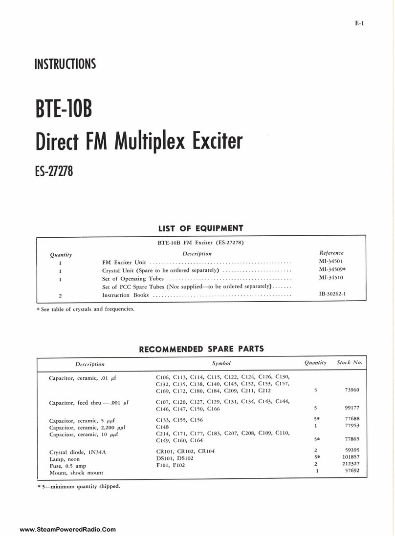
RCA 76-B2 User manual

INSTRUCTIONS
for
RCA SPEECH INPUT
TYPE 76-B2
(MI -11613-A)
RCA Victor Division
RCA Manufacturing Company,
Camden, N. J., U.
A Service of the Radio Corporation
Printed in U.S.A.
CONSOLETTE
Inc.
S. A.
of America
IB-24226

FIGURE I-TOP VIEW OF TYPE 76-82 CONSOLETTE WITH DOOR OPEN.
FIGURE 2 -BOTTOM VIEW OF TYPE 76-B2 CONSOLETTE WITH CHASSIS RAISED.
- 2 -

CONTENTS
Part I - Installation
SECTION TITLE PAGE
1Technical Data 5
2General Description 6
3Auxiliary Equipment 7
4Locating and Connecting Equipment 9
(A) Location of Equipment 9
(B) Wiring to Type 76-B2 Consolette 9
(C) Wiring to Auxiliary Equipment 9
(D) Audio Input Connections 10
(E) Audio Output Connections 10
5Addition of Signal Lights 10
(A) Studio "On Air" and "Audition' Signal Lights 10
(B) Control Room "On Air" Signal Light 10
(C) Console Signal Lights 11
6Installation of Announce Booth Speaker and "On Air" Light 11
7Instantaneous Recorder 11
Part II -Operation
8General Description 24
(A) Program Channel 24
(B) Audition Channel 24
(C) Remote Line Cue and Phone 25
(D) Over -ride Switch 25
9Emergency Program Channel 26
10 Emergency "B" Supply 26
11 Relay Operation 26
12 Speaker Relay Interlock 26
13 Light Relay Interlock 27
14 Suggested Operating Procedure 27
(A) To Place a Program on the Air 27
(B) To Audition Studio "B" While Studio "A" is On The Air 28
(C) To Cue Studio 4' from Studio "A" and Then Place Studio "B" On The Air 28
(D) To Cue Studio "B" from a Cue Line and Then Place Studio "B" On The Air 28
(E) To Talk -Back to Either Studio "A" or Studio "B" 29
15 Emergency Use of Monitor Amplifier 29
16 Network -Monitor Feature 29
Part ZEE -Maintenance
17 Inspection and Checking 29
18 Care of Control Switches 30
19 Voltage Measurements 31
Part Mr - Replacement Parts List
20 Items Located on the Pre -Amplifier Mounting Plate 33
21 Items Located on the Program Amplifier Mounting Plate 35
22 Items Located on the Monitor Amplifier Mounting Plate 37
23 Items Located on the Relay Mounting Plate 39
24 Items Located on the Transformer Mounting Plate 39
25 Items Located on the Front Panel Assembly 39

ILLUSTRATIONS
FIGURE TITLE PAGE
1Top View of Type 76-82 Consolette with Door Open 2
2Bottom View of Type 76-82 Consolette with Chassis Raised 2
36 db Pad for Telephone Line 8
4Suggested Recording Set-Ups 12
5Front Panel Layout 13
6MI -11702 Relay and Mounting Cabinet 13
7Installation of Type 76-B2 Consolette 14
8Location of Conduit Holes in Type 76-92 Consolette 14
9Schematic of VU Meter Switch and Pad to include an Extra 6 db Loss 15
10 Loudspeaker Connections for 1, 2, or 3 Studio Operation 15
11 Typical Conduit Layout 16
12 Conduit List 17
13 Simplified Schematic of Control Circuits 18
14 Announce Booth Relay Circuits 19
15 Block Diagram 20
16 Schematic Diagram of Type 76-82 Consolette 21
17 Speaker and Light Relay Operation (2 or 3 Studio) 22
18 Speaker and Light Relay Operation (Single Studio) 23
19 Parts Layout - Pre-Amplifier Mounting Plate 32
20 Parts Layout - Program Amplifier Mounting Plate ,II.
21 Parts Layout - Monitor Amplifier Mounting Plate 36
22 Parts Layout - Transformer Mounting Plate 38
23 Parts Layout - Relay Mounting Plate 38

PART / -INSTALLATION
I. TECHNICAL DATA
POWER REQUIRED
or,
GAIN (Continued)
(A) 1MI -11301-A Power Unit,
(B) a -c - d -c Supply:
(C)
(D)
Line Input to Line Output:
55 db
Microphone Input to Monitor Output:
(1) Plate (d -c): 110 db
Term.# Volts Milliamperes (E) Transcription Input to Monitor
Output: 81 db
116 345 60.0
115 185 1.5 (F) Line Input to Monitor Output: 54 db
114 290 5.5
104 280 43.0 (G) Cue Input to Monitor Output: 34 db
105 205 4.8
106 Reg. 235 17.0 (H) Talk -Back Input to Monitor Output:
Emg. 195 14.0 96 db
(2) a -c Filament: (I) Line Output to Monitor Output:
30 db
Terminals Volts Amperes
(J) Microphone Input to Emergency Line
#112 & #113 6.2 2.7 Output: 90 db
#109 & #110 6.2 1.6
#107 8 #108 6.2 0.3 (K) Remote Line Through Override:
#101 & #102 6.2 2.4 29 db (approximately)
(3) d -c Relay:
Terminals Volts Milliamperes
#117 & #118 60 110
RADIOTRONS
11 RCA -1620 (Metal) or '11 RCA -6J7
2RCA -1621 (Metal) or ' 2RCA -6F6
2RCA -1622 (Metal) or "2RCA -6L6
"May be used when maximum uniformity of
characteristics, and minimum of micro -
phonics, hum, and distortion are not re -
required.
GAIN
(A) Microphone Input to Line Output:
112 db
(B) Transcription Input to Line Output:
82 db
LINE OUTPUT LEVEL
Normal, +16 db"' with 0.5% r.m.s. Harmonic
Distortion from 50 to 7,000 Cycles
Maximum, +26 db.* with 1.0% r.m.s. Harmonic
Distortion from 50 to 7,000 Cycles
INPUTS
3
(A) Six 30/250 -ohm microphone inputs
(Balanced)
(B) Six 150/300/600 -ohm line inputs
(Balanced)
(C) Two 250 -ohm transcription inputs
(Unbalanced)
(D) One 250 -ohm talk -back microphone
(Balanced)
(E) Five 20,000 -ohm monitor cue lines
(Balanced)
se Note: 0 db = 0.001 Watts TRADEMARK "RADIOTRON" REG. U. S. PAT. OFF. BY RCA MFG. CO., INC.

OUTPUTS
(A) One 500/600 -ohm line
(8) Three 15 -ohm monitor lines
(C) One high -impedance headphone output
(2,000 to 5,000 -ohms)
LINE OUTPUT NOISE LEVEL
At Normal (72 db) Gain
60 db below Normal Output 16 db.")
DISTORTION
(A) Microphone Input to Line Output:
0.5% r.m.s. Harmonic Distortion
from 50 to 7,000 cycles, with normal
output of +16 db"
(B) Microphone Input to Monitor Output:
4.0% r.m.s Harmonic Distortion from
50 to 7,000 cycles, with 8.0 watts
output.
2. GENERAL DESCRIPTION
FREQUENCY RESPONSE
(A) Microphone Input to Line Output:
± 2.0 db 30 to 15,000 cycles.
(B) Microphone Input to Monitor Output:
+ 2 db from 30 to 15,000 cycles
(Audition Channel)
MONITOR POWER OUTPUT
(A)
(8)
4.0 Watts (+36 db") with 2% r.m.s.
Harmonic Distortion from 50 to 7.000
cycles.
8.0 Watts (+39 db") with 4% r.m.s.
Harmonic Distortion from 50 to 7,000
cycles.
PHYSICAL SPECIFICATIONS
(Overall)
Width -39 inches
Depth - 17 Inches
Height - 104 Inches
Weight - 135 Pounds (Unpacked)
The Type 76-62 Consolette has been designed for use in Broadcast Speech Input Installations to pro-
vide a complete and flexible system in one conveniently arranged control cabinet. All the necessary
functions of switching, mixing, and amplifying the audio outputs of microphones, transcription turn-
tables, or remote lines, auditioning, and monitoring are accomplished in a single consolette.
The Type 76-B2 Consolette consists of a cabinet containing the amplifiers, relays, transformers,
etc. mounted on a hinged chassis, and a sloping panel on which are mounted a large type vu meter, at-
tenuators, switches, controls, jacks, etc. The vu meter is also used in connection with the "Tube
Check" switch for checking the condition of the Radiotrons.
The Radiotrons are easily accessible for inspection and servicing by raising the lid of the Con-
solette. Two spring catches are made flush with the lid and are operated by turning through 90 degrees
with a thin coin or small screwdriver.
The entire upper section of the Consolette is hinged along the back and may be raised for reaching
the terminal boards, or for servicing the amplifiers and other components. Three terminal boards for
external connections are provided, and the high level audio terminals are separated from the low level
terminals. See Figure 2.
Metal tubes are used throughout, and in order to secure minimum vibration, the high gain tubes are
rubber shock -mounted on their respective mounting plates. These tubes are actually double shock -mounted
since the mounting plates are also shock -mounted.
Five rubber -cushioned mounting plates are located on the hinged chassis as follows (left to right):
(1) Relay Mounting Plate, on which are mounted the three relays, capacitors, resistors, etc. Two
Terminal Boards used for easy change over from two (or three) studio to single studio oper-
ation are also located under this plate.
- 6 -

(2) Monitor Amplifier Mounting Plate, on which are mounted the components of the monitor amplifier
and monitor amplifier booster stage.
(3) Line Transformer Mounting Plate, on which are mounted the two line transformers and associated
resistors.
(4) Pre -Amplifier Mounting Plate, on which are mounted the four pre -amplifiers.
(5) Program Amplifier Mounting Plate, on which are mounted the components of the program amplifier
and the program amplifier booster stage.
3. AUXILIARY EQUIPMENT
The additional apparatus required to provide complete operation of this equipment will depend
partly, of course, on the individual installation, including the number and arrangement of studios and
booths, etc. The type of installation described in this book has been designed to fulfill as completely
as possible the average requirements of a broadcasting station for which the equipment is intended.
These instructions will also serve as a guide to the customer in case his installation is not exactly as
described herewith.
(A) Microphones. This equipment will normally handle two microphones in each of two studios, a
fifth microphone (for announcing) in the control room, and, if desired, a sixth microphone for
an announce or transcription booth. Terminals $9-10, and #(47-48 may be connected in parallel
when the same microphone is used for control room announcing and talk -back. It is recommended
that RCA 44-8X, 74-8,77-B1,0r 77-C1 Ribbon Type Microphones be used for program pickup. The
RCA 88-A Pressure Microphone will generally be found satisfactory for control room announce
purposes. An RCA MI -6226-A Aerodynamic Microphone and MI -6227 Table Stand are suggested for
the talk -back circuit.
(B) Microphone Stands. The quality and type of stands required depend on the number and type of
microphones to be used. The most suitable program type floor stand for use with all the above
mentioned microphones is the RCA -Type 90-A. However, a lower priced stand (MI -4068-A) is also
available for use with all except the 44-BX Microphones.
The Type 91-A Announce Type Desk Stand should be used with the 44-BX Microphone, and the
Type 91-8 Desk Stand is recommended for use with the other microphones.
(C) Transcription Turntable. RCA Type 70-C Transcription Turntables are recommended. The Type
72-C Recording Attachment and 71-C Vertical Pickup Attachment may be used with the Type 70-C
Transcription Turntable.
(D) Type 73-A Deluxe Recorder. If the highest quality recordings are desired the Type 73-A Deluxe
Recorder is recommended.
(E) Recording Amplifier. The Type 82-B, 82-C, or 94-D Amplifiers are recommended for driving
either the Type 73-A or 72-C Recorders.
(F) Loudspeakers. The RCA Type 64-B (MI -44i0 Speaker Mechanism in MI -4400 Cabinet) Loudspeaker
should be used in the control room, lobby, studios, and listening rooms where the greatest
fidelity is required. Type UZ-4309 Loudspeaker Units mounted on suitable baffle boards are
also satisfactory for high quality reproduction. In the event that high-fidelity reproduction
is not required for the studios, and announce booth, the RCA MI -6261 with MI -6294 Cabinet is
recommended.
(G) Studio And Announce Booth Light Relays. See Section 5 on "Addition of Signal Lights" on
page 10.

(ii) Announce Booth Speaker Relay And Power Supply. See Figure 14 "Announce Booth Operation" on
page 19 .The MI -11703 Relay is complete with capacitor and resistors. A Type 79-A Power
Supply may be used.
(I) 76-B2 Power Supply. The MI -11301-A Power Supply Unit. See Section 1 -"Technical Data".
(J) Conduit Terminating Box. See Figure 7 "Installation Diagram" on page 14 .In many cases the
conduit terminating box is fabricated by the electrician, or made up on special order. In
such cases, the mounting flanges may be turned outward, instead of inside, as shown by
Figure 7.
(K) 6 DB Pad For Telephone Line. See Figure 3 on this page. This 600 -600 -ohm pad is placed
between the output of the Type 76-B2 Consolette and line jacks in order to permit the Type
76-B2 Consolette to operate into a constant impedance at all times.
The resistors comprising this pad may be ordered as follows:
100 -Ohm Resistor, Stock 430540, (4 required)
400 -Ohm Resistor, Stock 030498, (2 required)
When this 6 db pad is inserted in the telephone line the V.I. Meter will read the output
of the Type 76-B2 Consolette to the pad and not the program level to the line. In order to
read the actual program line level it will be necessary to subtract 6 db for the loss in the
pad. This may be done by changing the connections to the V. I. attenuator as shown in Fig-
ure 9 page 15 .
(L) Type 9-AJI Rack Or N1-11500 Wall Box.
See Figure 11 "Typical Station Conduit
Layout". The line jacks, line equali-
zers, and 6 db telephone line pad may
be mounted in an MI -11500 Wall Box, or
on a Type 9-AJX Rack if more space is
required than provided on the MI -11500
Wall Box. The MI -11500 Wall Box will
accommodate up to 4 MI -4645 (Type
33-A) or 6 MI -4646 (Type 33-B) Jack
Panels and 1MI -4162 Type 56-E Line
Equalizer.
(m) Radiotrons. The types and number of
each required are listed under
section 1 "Technical Data" on page 5 .
(N) Wall A Floor Outlets, For Microphones,
Signal Lamps, Loudspeakers, And Turn-
tables. Refer to Figure 11 "Typical
Conduit Layout" on page 16 .The out-
lets and boxes recommended are listed
in Figure 11.
10011 RESISTOR ,STOCK
40011 RESISTOR STOCK *30498.
TO 60011
LINE OUT
OF 76-B2
10011
TO soon
TEL. LINE
MI -11613-A K-I 81563-1
FIGURE 3 -6 DB FOR TELEPHONE LINE.

4. LOCATING AND CONNECTING EQUIPMENT
(A) Location Of equipsent. Because of the flexibility of the Type 76-62 Equipment, suggestions
only can be offered in this respect. See Figure 11 "Typical Conduit Layout" on page 16. The
Type 76-82 Consolette, the MI -11301-A Power Supply, the talk -back microphone, and the monitor-
ing loudspeaker are normally located in a control room between the studios, with glass windows
between the control room and studios so that the control operator can observe the action in
the studios. The transcription turntables are usually located in the announce and transcrip-
tion booth, but in certain cases may be located in the control room. The Consolette is nor-
mally located on a desk or table, the power supply being mounted on the wall of the room. The
exact location and layout of the equipment depend on the architectural arrangement of the
station and other conditions of the specific installation.
(B) Wiring To Type 76-B2 Consolette. All external wiring should be connected to the Consolette
through the three terminal blocks on the base of the cabinet and which are available by lift-
ing the chassis. The audio terminal board with solder type terminals is at the right and rear
of the base (when facing from the front), and the two power terminal boards with solder and
screw type terminals are on the left hand side of the base. The audio and power leads should
be kept as far apart as possible at all times.
Refer to Figure 7 "Installation of Type 76-82 Consolette" and Figure 8 "Location of Con-
duit Holes in Type 76-82 Consolette". Four 1-5/8 inch diameter conduit holes are located in
the rear of the Consolette, and four similar holes are located in the base. Referring to the
typical installation in Figure 7, the four flexible conduits run from the base (or rear) of
the Consolette to the Conduit Terminating Box located in the floor (or wall). Four 1-5/8 inch
diameter holes are drilled in a section of the junction box and the conduits terminated to
this section The leads can then be pulled through the other opening in the conduit box.
IMPORTANT: All shielded leads to the Consolette should not be cut at the junction box, but
should be pulled through in a continuous piece to the Consolette.
Connection information is provided by Figure 12 "Conduit List". Figure12 also lists the
lead sizes to be used and the conduits in which the leads should be run. For example: Con-
duit $2 runs from the power box to terminals $21 and $22 of the 76-B2 Power Supply (MI -11301-
A). This circuit is the AC supply and 1 pair of 600 -volt stranded shielded twisted leads is
used.
Care should be exercised when attaching conduits to the rear of the Consolette to avoid
damaging the shielded cables of the Consolette. If necessary, the hold-down clamps may be
loosened and the shielded cables moved slightly in order to facilitate adding the fittings to
the conduits. The clamps should then be replaced.
Refer to Figure 10 and Figure 13. These figures contain information for terminal strap-
ping for 1, 2, or 3 studios. As shipped from the factory, the Consolette is connected for 2
studio operation, and the terminal strapping for these two terminal boards must be changed as
shown in Figures 10 and 13 if 1 or 3 studios are used.
(C) Wiring To Auxiliary Squipsent. All conduits are arranged so that AC power leads are oot run
in the same conduit with audio leads, and that low level audio leads are not run in the same
conduit with high level audio leads or loudspeaker field supply leads. The power for 1, 2,
or 3, 100 -volt, 1.000 -ohm, 10 -watt loudspeaker fields may be obtained from the MI -11301-A
Power Supply. The instructions in the Power Supply Instruction Book should be carefully
followed. If other speakers which have different field voltages and power ratings are used,
a separate field supply unit (or units) such as the RCA Type 79-A, or similar, must be pro-
vided.
- 9 -

(D) Audio Input Connections: The audio input terminals of the Consolette are normally connected
for microphone and input line impedances of 250 -ohms, and the input terminals are connected
to the 250 -ohm terminals (terminals 1 and 6) of the transformers T-1, 1-2, T-3, and 7-4.
Should it be desired to use 30 -ohm microphones or lines, the input terminals must be discon-
nected within the Consolette from the 250 -ohm primaries of the input transformers T-1, 1-2.
1-3, and 1-11, (terminals 1 and 6), and connected to the 30 -ohm primary terminals (2 and 5).
As indicated on Figure 16 page 21 (Schematic Diagram) terminals Si, #3, 05, and #7 of the
inputs should be connected to similar terminals of RCA microphones for proper phasing.
On many types of remote lines, the frequency response of the line can be improved with
or without equalizers by operating them into 150 -ohms. This can be done by reconnecting 1-9
and T-10 for 150 -ohms on their inputs. (Remove the ground wire and jumper between 3A and 18
and reconnect 3A to 3B and IA to 18).
(E) Audio Output Connections. The line-out terminals (#79 and 080) of the Consolette are designed
to operate into a 500 -600 -ohm telephone line. On some types of telephone lines it is ad-
vantageous to insert a 6 db pad between terminals #79 and #80 and the telephone line (See
Section 3-K).
5. ADDITION OF SIGNAL LIGHTS
(A) STUDIO "OA AIR" AND "AUDITION" SIGNAL LIGHTS
(1) EQUIPMENT REQUIRED! For the typical layout shown in Figure 11, the following equipment is
required for the two studios:
4MI -11702 Relays and Capacitors
2Mounting Boxes. See Figure 6.
Studio light equipment; type to be selected by customer to
harmonize with the architectural treatment of the studio
Note: The 0.5 Mfd. capacitors are not required on the 4 relays.
(2) LOCATION, MOUNTING, AND WIRING. The relays should be mounted in metal boxes as shown in
Figure 6 and located near the respective studios. Conduits 01, #5, #11, and #33 are the
studio lights. Figure 16 provides connection information. The relays energizing volt-
ages are obtained from the MI -11301-A Power Supply through the following terminals on the
Consolette:
#124 Common Terminal for Studio "A" "On Air" and "On Audition" relays
#125 For Studio "A' "On Air"
#123 For Studio "A" "On Audition"
0127 Common Terminal for Studio "B" "On Air" and "On Audition" relays
#126 For Studio "B" "On Air"
#128 For Studio "B" "On Audition"
(B) CONTROL ROON "01 AIR" SIGNAL LIGHT
(1) EQUIPMENT REQUIRED: If the control room "On Air" light, shown in Figure 11, is to be
installed the following equipment is required in addition to that above.
1MI -11702 Relay and Capacitor
1Mounting Box. See Figure 6.
1Resistor, 175 -ohms, 10 -watts
- 10-

(2) LOCATION, MOUNTING, AND WIRING. The relay should be mounted in metal box as shown in
Figure 6, and located near the control room. Conduits #43 and #45 shown in Figure 11are
for the control room light.
The relay energizing voltage is supplied by the voltage drop across the 175 -ohm,
10 -watt resistor connected in series with the high side of the relay supply circuit from
the MI -11301-A Power Supply. See Figure 13.
Connections should be made as follows:
1. Connect the high side of the relay supply circuit from the MI -11301-A
Power Supply to terminal #122 instead of #118 on Consolette.
2. Connect terminal #118 to #121.
3. Connect the 175 -ohm, 10 -watt resistor across the control room "On Air"
light relay.
4. Connect control room light relay to terminals #121 and #122 on Consolette.
(C) CONSOLE SIGNAL LIGHTS
Plug buttons (one at either side of the meter) are mounted in the front panel and
wiring is provided to facilitate the addition of two signal lamp jacks. Signal lights,
such as 'Pre -Set" and "On Air", which can be operated from the master control room in
large studio installations can thus be used. Terminals #67, #68, #69, and #70 are pro-
vided for external connections (See Figure 16). The following equipment is recommended:
(a) Lamp Jack, RCA Catalog #26562 (Two required)
(b) Lamp, RCA Catalog #26563 (Two required)
(c) Lamp Cap (Red), RCA Catalog #17930 (One required)
(d) Lamp Cap (Green), RCA Catalog #17931 (One required)
6. INSTALLATION OF ANNOUNCE BOOTH SPEAKER AND "ON AIR" SIGNAL LIGHT
(A) WINDT REQUIRED:
1MI -11702 Relay and Capacitor
1MI -11703 Relay and Capacitor
1Mounting Box. See Figure 6.
(B) LOCATION, MOUNTING, AND WIRING. Refer to Figure 14 which provides connection information.
The relays may be mounted in steel boxes as shown in Figure 6. The relay energizing voltages
are obtained from the Type 79-A Power Supply, and controlled through terminals #75 and #76 of
the Consolette. The booth speaker audio power is obtained through terminals #135 and #136 of
the Consolette. The 15 -ohm, 5 -watt, resistor replaces the loudspeaker voice coil when the
loudspeaker is "Off". The filters across the relays reducrclicks. Conduits #6, #17, and
#32 are for the announce booth speaker and "On Air" light.
7. INSTANTANEOUS RECORDER
The RCA Type 72-B or 72-C Instantaneous Recorder, or 73-A Deluxe Recorder may be used with the Type
76-B2 Consolette for recording auditions, broadcasts, etc. The recording terminals #41 and #42, which
are for bridging, may be used for recording in the following manners. (See Figure 4):
- 11-

(A) EQUIPMENT REQUIRED:
(1) SEE FIGURE 4-A.
One pad, consisting of two 120 -ohm (Stock 030189), and one 560 -ohm
(Stock 05164) resistor.
One Type 87-A (MI -11215) Booster Amplifier.
Two 120 -ohm (Stock 030189) resistors,
One Type 82-8 (MI -11205) Monitor Amplifier with Volume Control.
(2) SEE FIGURE 4-8.
One pad, consisting of two 120 -ohm (Stock 030189), and one 560 -ohm
(Stock 05164) resistors.
One Type 82-C (MI -11209) Monitor Amplifier.
(B) CONNECTIONS:
Connect above equipment as shown in Figure 4.
Connect to the Type 76-B2 Consolette as shown by the Schematic Diagram,
Figure 16.
76-B241
EXTERNAL
RECORDING
AMPLIFIER42
0
0
12.11.
12011
560/1
0TYPE 87-A
Z BOOSTER
AMPLIFIER
A
0
REMOVE GROUND ON TERM"!
OF INPUT TRANSFORMER IN
TYPE 67-A AMPLIFIER
12011
12011.
50f1 ofI
2500211
TYPE 82-B AMPLIFIER
VOLUME CONTROL
QTYFE 82-B
OGNO.
AMPLIFIER
0
0011.-10WATTS
TYPE 72-B ,72-C OR
73-A RECORDER.
TYPE 87-A AMPLIFIER CONNECTED FOR TYPE 82-B AMPLIFIER CONNECTED FOR
25011. INPUT AND 50011. OUTPUT 50011 INPUT AND MD. OUTPUT
76-82
41
EXTERNAL
RECORDING
AMPLIFIER42
12011
56011
co
12011 0
TYPE 82-C
AMPUF1ER 0
10/1 10WATT
REMOVE CENTER TAP GROUND
ON INPUT TRANFORMER OF
TYPE 82-C AMPUFIER
TYPE 72-8,72 -C OR
73-A RECORDER
TYPE 82-C AMPLIFIER CONNECTED FOR
25011 INPUT AND 150. OUTPUT
12011 RESISTOR - RCA STOCK NO. 30189
56011 RESISTOR- RCA STOCK NO. 5164
MI -11613-A P-1 70755-0
FIGURE 4 -SUGGESTED RECORDING SET-UPS.
- 12-

PK-3 V I. METER PK-I
REMOTE CUE
c7o im
A TBBALID. M I2CgE45
000000000
MONITOR INPUT
PK-4
OVERRIDE OFT RECORD
=.0==.
K-9
PHONES MONITOR
0mmor4
REMOTE
PRO
TUBE CNECA
K-1 K-2
VI CONTROL
DEReD,
INPUT 0 0
T T 0I 23456
000000000
MI XER61 NPUT
K-3 K-4 K-6
A ._07.P AS PALCL. P
oQ5D
ANNOUNCE
REMOTE
LOCAL
K-8
LINE OUT
EMG .00REG
MA ST ER
----- PK-2
J-1 P-2 K-10
MIXERS
FIGURE 5 -FRONT PANEL LAYOUT.
K-7 P -I
MI -11613-A P -170508-I
OUTLINE S.
MOUNTING
DIMENSION 5
FOR MI-
NO.11702
RELAY
2 HOLES FOR
NO. 6 SCREW
1-1
RELAY
0 0
I1
RELAY
0MOUNTING BRACKET
NO. 6 SCREW
TWO MI -11702 RELAYS MOUNTED IN TYPE A 6X6X4 COLUMBIA STEEL CABINET.
MI -11702 P-170515 -I
FIGURE 6 -MI -11702 RELAY AND MOUNTING CABINET.
- 13 -

JUNCTION BOX MAY
BE SET IN WALL
OR FLOOR AS SHOWN.
NOTE: CONDUITS MAY
CONNECT TO BACK OF
CONSOLETTE IF MORE
CONVENIENT.
SPACE 7'. OR
MORE FCR
RAISING CHASSIS
TYPE 76-B2 CONSOLETTE
FOURFLEXIBLE
STEELCONDUITS
OPTIONAL METHOD
OF INSTALLATION[l
P.1CS
WINDO
JUNCTION BOX TO BE ORDERED WITH ONE-
PIECE DETACHABLE COVER PLATE.
CUT AS SHOWN AND DRILL FOUR HOLES
ONE AND FIVE -EIGHTS DIA.FOR CONDUITS
TO SUIT WHEN INSTALLING.
et
/ JUNCTION
Y77/127-/Z-7/777 97/7/7/7/7/7, 977;11:1 )7 17=
CONDUIT
MI -11613-A P-170523-2
BOX
WALL
0
7
0 0 0
le
ie
0
TOP VIEW
SIDE VIEW
COLUMBIA STEEL CABINET TYPE A
SIZE 12 x 18 X 6 IS RECOMMENDED IF
WALL THICKNESS IS AVAILABLE.
(12 X18 X 4 CABINET MAY BE USED.)
FIGURE 7 -INSTALLATION OF TYPE 76-B2 CONSOLETTE.
END VIEW
10s2117
I
r
t
REAR
7
i
VIEW -1g DIA.8 HOLES
__.1
-+17,--1
I5-ir
,Ig
:19;
2-....- 2 II 13
1916
18-1
MI -11613 -A P -I 70 510-1
FIGURE 8 -LOCATION OF CONDUIT HOLES IN TYPE 76-B2 CONSOLETTE.
I-85

ZERO
A DJ.
12DB
V8D8 S4DB S2DB SIDB IN
-J
OFF 18VU IV
0
0VU
VU
REAR
0 DECK
00VOLUME
INDICATOR
CONTROL
(REAR VIEW)
GC L
-
WIRES INDICATED BY DOTTED
LINES NOT TO BE CHANGED.
OF F 1218 0
vu
i
1I',FRONT
'Is-9 DECK OFF
I11 .ac;1 9-
II
1IILt
0 0
VU 0,4VU
C
J
VOLUME
I N DICATOR
ZZ
MI-H613-A M-140853-0
FIGURE 9 -SCHEMATIC OF VU METER SWITCH AND PAD TO INCLUDE AN EXTRA 6DB LOSS.
(A) FOR SINGLE STUDIO OPERATION (2-1511 SPEAKERS)
*STRAP TERMINALS I& 2: * *CONNECT T -I 5 AS SHOWN
2
I
0304
6
5
4
(B) FOR TWO STUDIO OPERATION (3-15R SPEAKERS):
* STRAP TERMINALS I 3.2,AND 38.4: * CONNECT T -I5 AS SHOWN:
2
1
4
( SEE NOTE NO. I)
60
5
4
(C) FOR THREE STUDIO OPERATION (4-15f1 SPEAKERS):
* STRAP TERMINALS 28.3
01 6
9263 5
04 4
9
8
CONNECT T-15 AS SHOWN:
THESE TERMINALS ARE
LOCATED ON A SMALL 4 -
TERM I NAL BOARD ON THE
BOTTOM OF THE RELAY
MOUNTING PLATE.
*4(WHEN MAKING OR CHANG-
ING CONNECTIONS TO T-15,
DO NOT DISTURB THE CON-
NECTIONS TO TERMINALS NO.
I, 3, 7, 8, & 12 T -I 5 (K-901040
IS LOCATED ON THE MONITOR
AMPLIFIER MOUNTING PLATE.
MI -11613-A P -170 519-I
NOTE NO. I: THE CONSOLETTE IS CONNECTED AT THE FACTORY AS SHOWN IN PART B.
FIGURE 10 -LOUDSPEAKER CONNECTIONS FOR I, 2, OR 3 STUDIO OPERATION.
- 15 -

POWER LINE WALL
TO POWER SWITCH 8 FUSE BOX
1
2 3 4 5 6 7
STUDIO A
,11-)..1-8M-11412/1Vb
"ON AIR -LAMP (0:11_
-AUDIT ION- LAMP _9, RELAY r -
CUE SPEAKER- -
--------------- --
ANNOUNCE AND [TEL. LINES WALL
4_11703i. TRANSCRIPTION BOOTH, 1TERMINAL BOX
RELAY: ON AIR'',
_..,1 .M1-117024
--
1' ; 79-A L -4041i<1 SPKR LAMP ...' 13"41- RELAY t.-
1
i
IPOWER
ISUPPLY1
SEE FIG.1 4 !MIC,
17-1! 1[7-2i
,--- , -
2r, .',)
1-1-61 'isl- I' -i1/4. 18.7 II,LT. li
--.' - --i 18 -4 '1
19-J
_17'------17--------,1ii1
f-\--Cy
M1C.I a\ AI
MIC.2
1 -M1 -11301-A
POWER 1415
SUPPLY
(A) MI -4624 WALL RECEPTACLES IN
OUTLET BOXES SIMILAR TO G.E.
SP -5800.
(B) OUTLET BOX G. E. SP -3400 WITH
G.E. SP -34R2 COVER, OR SIMILAR.
(C) FLOOR BOX G.E. SP -8300 WITH
G.E. SP -8339 OUTLET,OR SIMILAR.
(D) FLOOR BOX G.E. SP -8300 WITH
G.E. SP -8359 OUTLET,OR SIMILAR.
NOTE: DOTTED LINES INDICATE
AUXILIARY EQUIPMENT -NOT PART
OF 76-B2
18
10
12
TO OFFICE _20_,
SPEAKERS
TALK BACK
MICROPHONE
21
p45
CONDUIT TERMINATING BOX
IN WALL OR FLOOR
212 I214
2P I215
76-B2
CON SOLETTE
CONDUIT MAY BE
BROUGHT IN REAR
OR BOTTOM OF
CON SOLETTE SEE
FIGURE 7
-32
28
33
6 DB PAD
MOUNT IN
MI -11500
BOX. SEE
FIG. 3
38
3837
31
9AJX RACK
OR
MI -11500
WALL BOX
FOR
LINE JACKS
AND
EQUALIZERS-1
TEL. CO.
STUDIO B
r TWO 1 -34- _'ON AIR- LAMP
MI -H 702r 031- 'AUDITION'LAMP
H RELAYS I- 35----
42 -'TO STATION
GROUND
[MONITOR
SPEAKER
_1
ITO TRANSMITTER IF
43 IN SAME LOCATION
\jI
ci0 >-r- <II- jr17141
1- ixj44
:Bi
I;..ON AIR -LAMP
CONTROL ROOM
ANNOUNCE MIC.
FIGURE II -TYPICAL CONDUIT LAYOUT.
- CUE SPEAKER
MIC. I
MIC 2
MI -11813-A 7-180434-4

Note 41:
Note *2:
Note *3:
Note 44:
Note *5:
Conduit List for Type 76-B2 Consolette
Refer to Conduit Layout (Figure 11).
Terminals underlined are located on Type 76-B2 Power Supply (MI -11301-A).
Asterisks (') indicate optional equipment - not part of 76-82 (Shown dotted on Figure 11).
Wire -A=MI -64 (#20 AWG Stranded -300 -volt shielded twisted pair).
B=MI -65 (#16 AWG Stranded -600 -volt shielded twisted pair).
C=Pair #14 Lead Covered
Group wires as follows from conduit box to 76-82:
(a) Include in Conduits 22 and 23 wires from filament, plate, d -c to relay, audio
to speakers, station ground.
(b) Include in Conduits 24 and 25 wires from microphones, turntables, remote lines,
K-1 15 65-1
CONDUIT SIZE
cue lines, line out.
FROM TO WIRE CIRCUIT
.
TERMINALS
'1
2
3
4
.5
*6
'7'8 ....
9
4.
4
9.
9
4
i
9
#.
i
Power Box
Power Box
Power Box
Power Box
Power Box
Power Box
Power Box
MI -11702 Relay
MI -11702 Relay
MI -11702 Relays
76-82 Power Supply
TT -1
TT -2
MI -11702 Relays
MI -11702 Relays
TT -1 (Booth)
"On Air" Light
Studio A .....
"Audition" Light
Studio A
1-C AC Supply
1-C AC Supply
1-C AC Supply
,1-C .AC Supply
.1-C AC Supply
1-C .AC Supply
1-C . AC Supply. ..
1-C AC
1-C .AC ..........
AC
Z1-22
AC of TT -1
AC of TT -2
AC
AC
AC
AC
AC
10 76-62 Cue Speaker .1-6 Speaker Audio 133-134
76-B2 Power
Supply Studio A ... 1-B Speaker Field r_12 and one side of
LStudio B Speaker Field
11 76-62 Studio A "On Air"
Light Relays 2-A DC to Relays
[124-125
123-124 "On Audition"
12 ..9. ..76-62 Studio A
Microphones ....... 2-A ...Microphone 1-2, 3-4
13 ..9 ..... Mic 1 Studio A Mic 2 Studio A ...1-A .Microphone
14 .. 14 76-62 Power
Supply
76-B2 , 4-B .Filament Supply. 1-2 and 101-102, 7-8
and 107-108, 9-10 and
76-B2 Conduit 109-110, 12-13 and 112-113
Box .1-B .Speaker Fields .19-20
15 ..19 76-62 Power 76-82 1-B Relay 17-18 and 117-118**
Supply 15-16 and 115-116
4-6 ... . .Plate Supply ...4-5 and 104-105
6-11 and 106-111
1-14 and 103-114
16 None .,.76-82 Talk -Back Mic ..Cord 1-A M crophone .47-48
*17 976-82 Announce 1-6 Audio to Booth 135-136
Booth Relay .. .1-A .. Relay Control 75-76
*18 4. ...Booth TT -1 Booth TT -2 1-C AC AC of TT's
*19 9Booth TT -1 Booth TT -2 1-A Audio Audio of TT's
*20 i76-B2 Off ice Speakers 1-B Audio 135-136
21 i76-62 TT -1 Audio
(Control Room) 1-A Audio 23-24
22 .14 See Note #5 above
23 .14 See Note #5 above
24 .14 See Note #5 above
25 .19 See Note #5 above
26 . . .... 9 .... 76-B2 TT -2 Audio
(Control Room) ... 1-A Audio 2 5-2 6
27 76-B2 Line Out ... 1-A Audio 79-80
28 #76-B2 Control Room
Announce Mic. 1-A Microphone 9-10
'29 4. 76-62 Booth Mic. .. 1-A .Microphone 11-12
*30 976-62 Booth TT's 2-A Audio 23-24 and 25-26
31 19 76-62 Remote Lines .. .6-A Remotes 31-32, 33-314
35-36, 37-38, 39-40
Cue Lines ...... ....5-A .....Cue r53-54, 55-56, 57-58
L59-60, 61-62
Line Out .. 1-A ..Audio 79-8C
32 Booth Relay Booth Relay
(MI -11702) (MI -11703) 1-C AC AC terminals of relays
33 76-62 Studio "On Air"
Light Relay .2-A DC to Relays
[126-127
127-128 "On Audition"
34 Studio B Studio
Light Relay 'On Air" Light 1-C AC
35 .#Studio B
Light Relay "Audition" Light 1-C AC
36 #76-B2 Studio B 1-B Audio 131-132
Conduit Box Cue Speaker 1-B Speaker Field side of Studio A
Spkr. Field and 1 side
of Monitor Speaker Field
37 76-B2 Monitor 1-6 Speaker Audio 129-130
76-82 Power Speaker One side of Studio
Supply 1-B Speaker Field LB Spkr. Field and 20
38 976-132 Studio B
Microphones .2-A Microphone 5-6, 7-8
39 Mic 1, Studio B Mic 2, Studio B 1-A .Microphone
'40 4. Announce MI -11703
Booth Speaker Relay 1-B Audio
'41 Booth "On Air" MI -11702
Lamp Relay AC
142 976-82 Station Ground 1-C .Ground 103
'43 976-B2 Control Room
Light Relay .. 1-A ... DC to relay 121 and 122
*44 9MI -11702 Relay "On Air" Light
Control Room 1-C AC AC
*45 4. . Power Box MI -11702 Relay 1-C .-.AC Supply AC
NOTE: If conduits 43, 44, and 45 are used refer to Sect ion 5-8, page 10 for connections to terminal #118.

ANNOUNCE BOOTH"ON AIR"LAMP
110 VOLTS AC RELAY
*INCLUDED 1 N
MI -11703 RELAY KIT
**INCLUDED IN
MI -11702 RELAY KIT
0.5 MFD**
15 fl 5 WATT
0
LOUDSPEAKER
(15 OHM)
79-A
POWER
SUPPLY
0
RELAY *
000b0060
a5 MFD*
BEFORE CON-
NECTING TO
135 C136 MAKE
CONNECTIONS
AS SHOWN IN
FIG. 10-C.
76-B2
TERMINAL
BOARD
075
o
1*
150011 50 WATT
200(1 5 WATT* 12 VOLTS
MI -I 1613-A M -I 40576-4
FIGURE 14 -ANNOUNCE BOOTH RELAY CIRCUITS.
076
0135
0136
- 19 -

0vi- 1
ON AIR RELAY -
AUDITION
PRE AMP. I
PRE AMP. 2
25O
MIXERS
IKI
K2
PGM.
I0AUD.
faC
TD- RELAY -ALL STUDIO LIGHTS & RELAYS
ARE EXTRA AND OPTIONAL
REMOTE
--0-1 K7-o-
LOCAL
PRE AMP 3
PRE -AMP. 4 /14
K3
o
0
K4
MASTER
VOL. CONTROL
PROGRAM
AMP.
METER
VU
MONITOR
VOL. CONTROL
MONITOR
AMP.
OI
T-611842
o67;9. PLATE CURRENTS
oa-OFF
VU CONTROL
K8oIREG.
OEin5M6..0 LINE OUT
-ON AIR
Ce"---IRELAY -.I- -
AUDITIONRELAY -
TT I
oMONITOR OUT
rr6"0RL 2
0'ALL KEY SWITCHES & RELAYS ARE
RL 3
INTERLOCKED WHERE REQUIRED
FOR TALK BACK CIRCUITS
MIXER 5 °7-
INPUT
PK I
MIXER 6
INPUT
PK 2
CUE
PK 3
EXTERNALLY
POWERED
-0--
r1-1 TT
r111-1 1-1 1-1
0C00 0 0
OFF 3456,
REMOTE LINES
411 T9p
T 10
'
T I TTT 2
.-0-- r'-o-- _o__ 5
r' 6
o
o
K
0K6
OVER
RIDE
0FRECORD'
oo oK9
0
REM. --- PGM.
0K10 0
PK 4
1_ 1_ 1_ 0_
c.1 rzi 77.71 REMOTE
-
000000
2345, EXTERNAL NET
CUE INES RECORDING MONITOR
AMPLIFIER
SIMPLIFIED BLOCK DIAGRAM OF 76BZ CONSOLETTE
PHONE
M )
ANN.
<1.
47M.
T. B. ON AIR
EXTERNALLY
POWERED
FIGURE 15 -BLOCK DIAGRAM.
- 20 -

W- 130087
THE FOLLOWING ARE BLANK
TERMINALS.
13,14.177022 INCL. 43,44,
491052 INCL. 631066INCL.
774.78, 119 & 120
2
DENOTES PHASING
LINE OUT
67 68 69 70 7 72 73 74 79 80
fl0 0ToT
LEFT RIGHT
FRONT VIEW
ftREG.
R-42 LINEOUT
-6
EG. ZERO
ADJ.
OUT B280 2.0109
aC
OPF 19Advtvt,o0
DECK o
VU VU 6VUgi
VOLUME
INDICATOR
CONTROL FRONT.
DECK OFF
VOLUME
INDICATOR
PRE -AMPLIFIERS
P-170234T901046
506, 46
078 4
N
3 0 -
MIC-2
40
5 0 -"4.
C5
2
T-2 r
620 1,21--5:T-27470
RCA
3 6 0 6
C-2 22. On8qq g-os
M D NI G7 Oq
05 MFD
MIXER NO.1
'41OUT
PGM
-g-b-I 4"
7500
anc-Fl .1 I
AUD
R-2 R-3
1000000 5600 22000
901046
MIC-3
60
lo
T-3
901046
50--0
C07
j,S 2
ANNOUNCE
LOCAL L
K-7
SHIELD
ACC -480
9
LOCAL
100-
1
II 0 ----
REMOTE
120
1540
160-,
TO PGM.
AMP. BASE
750
0
5
R-4
1000000 5600 22000
0
loarmon
T4-
901046
20-0
,0
3
RCA1620
RCA1620
'?
T-6274 7
5N
4
MIXER NO.2 14
PGV
IN OUT 2850
X1-27470
48
C- o
C-5 M D
0.5 FD
MIXER NO.3 8-15
IN
IL
7500 1I
75 UD.
K-3
PGM.
,___111z1D
4ft-
PROGRAM AMPLIFIER
P-170232 RCA C-11
1820
5
R-8 R-9
5600 22000
4
0.r {=r1
05
CO. -751
RCA1620
K-4 11---..-
.PGM.
XT 2747 MIXER NO.4 8-16 L.
f
LT-8 R-25
3IN OUT 2620 R-26 i
o2
0. c,-.$.
rii <.D c, ,,
A
8
N
16R20CA R-50 °C. -I8
90000 C
M04
0 000
53
Na[(moon
0
8
C -I 9
RCA 0.25 T -I2
620 M D. RT-525
1 026o6g
is-o
C
eA
,24
UU
7-13
R-102 R -I03
0100 100
0
c,
W0 113
IT.sd W 0112
WF
!22
X0110
X 0 109
VI-<- Y-0 108
is Y 0 107
Z 0 102
19-IK Z 0 101
R-10 R -I 1R -I2
VYVV-
100.0000 560.0 22000 MIXER NO.5
REMOTE
760
654
T-981-10=360. FROM
TERM. IA TO 3E1 8 44 0
FROM TERM. 4A TO 8B
LINE TRANS PLATE
M -I40262
3 2
10.0000 10.0000 10 0.0000
403.0 2 0
38 37 36 35 34 13 32 3
REMOTE LINES
9J
OFF TT -2 TT -I
R40024\40
2-
RoLH6
IN OUT
R 17
28511
MIXER NO.6 R-18
IN OU-T 2g n
-
K-5PGM
R-27 .1 I
E-
R 28
7500
7500. UD
K-6PGM
-o- REM
SX2 02
26 TT -2 25. 24 TT -I 23
%IN
75°n AUDI
00
41 42
EXTERNAL
RECORDING
AMPLIFIER.
r,
MONITOR AMPLIFIER
P-170237
1-14
901046o4C
OoO3
R-82
'101 R95 R-97
°X' 78
T -I5
K -90104I
O 104
o 105
0III
TOBASE P.
"--0 103
R-96
-VV1200.0
T-15=36.440 DC
FROM TERM.12 TO
7653.50 FROM
TERM 3 TO 7
-o 116
6-87
14000 R-66
4000R-85
0115
0 114
0 106123<z
ONAUDOo
12460
ONAIR125(90J
-116
R -I15
LOWER nt
SECTION 0.qo
PK-4 CUE
UPPER
SECTION
0. .0
J.3
.
MI -11813-A 05 3
0 0 4 00 0 000 0
W-130087- 2 62 61 60 59 58 57 56 55 54 53 46 45 48 47 119 120 121 122
CUE LINES ... BATALK
BACK
MIC.
0
0- -0
ONE MON. SW.
R 117 639
1AMFDRL-3
MONITOR
SPKR.
400
Cf-K-0-
89 el 03 9
Sler_t2 94 08
00 RL-2
1260
1ODNAIR <-.0
27 gdx
NAUDr_',3
1213<418
0 118
117
o 0 0 0
135 136 27 28
AUX. J -I
SPKR. MON.
PHONE
Other manuals for 76-B2
1
Table of contents
Other RCA Transmitter manuals