August 2016
2
Quick Start Guide
NOTICE
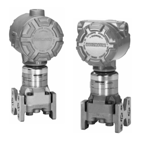
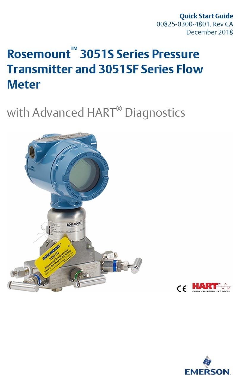
This guide provides basic guidelines for Rosemount 3051S Series Pressure Transmitters. It also provides the
basic electronic guidelines for the Rosemount 3051SFA Reference Manual, Rosemount 3051SFC Reference
Manual, and Rosemount 3051SFP Reference Manual. It does not provide instructions for diagnostics,
maintenance, service, or troubleshooting. Refer to the Rosemount 3051S HART Reference Manual for more
instruction. This document is also available electronically on EmersonProcess.com/Rosemount.
Explosions could result in death or serious injury.
Installation of this transmitter in an explosive environment must be in accordance with the appropriate local,
national, and international standards, codes, and practices. Review the approvals section of this guide for any
restrictions associated with a safe installation.
Before connecting a Field Communicator in an explosive atmosphere, ensure the instruments in the loop
are installed in accordance with intrinsically safe or non-incendive field wiring practices.
In an Explosion-Proof/Flameproof installation, do not remove the transmitter covers when power is
applied to the unit.
Use appropriately rated Ex adaptors, blanking elements, or glands during installation.
Keep process insulation at least 1-in. (25 mm) from transmitter connection.
Process leaks may cause harm or result in death.
Install and tighten process connectors before applying pressure.
Electrical shock can result in death or serious injury.
Avoid contact with the leads and terminals. High voltage that may be present on leads can cause electrical
shock.
Conduit/cable entries
Unless marked, the conduit/cable entries in the transmitter housing use a 1/2–14 NPT thread form. Entries
marked “M20” are M20 ⫻1.5 thread form. On devices with multiple conduit entries, all entries will have
the same thread form. Only use plugs, adapters, glands, or conduit with a compatible thread form when
closing these entries.
When installing in a hazardous location, use only appropriately listed or Ex certified plugs, adapters, or
glands in cable/conduit entries.
Contents
Mount the transmitter. . . . . . . . . . . . . . . . . . . . . 3
Consider housing rotation . . . . . . . . . . . . . . . . . 7
Set switches and jumpers . . . . . . . . . . . . . . . . . . 8
Connect wiring and power up . . . . . . . . . . . . . . 9
Verify configuration . . . . . . . . . . . . . . . . . . . . . . 15
Trim the transmitter. . . . . . . . . . . . . . . . . . . . . . 18
Safety instrumented systems installation . . . 18
Product Certifications . . . . . . . . . . . . . . . . . . . . 19
00825-0100-4801_RevMC.fm Page 2 Tuesday, August 9, 2016 6:39 AM

