MISCELLANEOUS
ADJUSTMENTS
HORIZONTAL
SWEEP
CIRCUIT
ADJUSTMENTS
SuggestedAlignment
Tools:
B3,
B4
GENERAL
CEMENT#8606,8606L,8282,
9295
WALSCO
#2526,
2543,
2544,
2545
Connect
a
0-500MA
meter
in
series
with
the
cathodecircuit
ofthe
Hori-
zontal
Output
tube.Connect
a .
47mfd
capacitor
across
the
meter
termi-
nals.
Connect
a
0-1MAmeter
in
series
with
the
cathode
circuit
ofthe
HV
Regulator
by
removing
the
test
jumper
and
connecting
the
meter
inits
place.Connect
the
high
side
ofthe
scopethru
a low
capacityprobe
to
point
<§>
. Low
side
to
chassis.
Connect
theDC
probe
ofthe
VTVM
thru
a
high
voltageprobe
tothe
High
VoltageRectifier"cup".Common
to
chassis.
Setthe
Focuscontrol
fully
counterclockwise.
Setthe
High
Voltage
Adjust
at
two-thirdsclockwiserotation.
Tune
the
receiver
toa
station
signal
and
synchronize
the
picture.
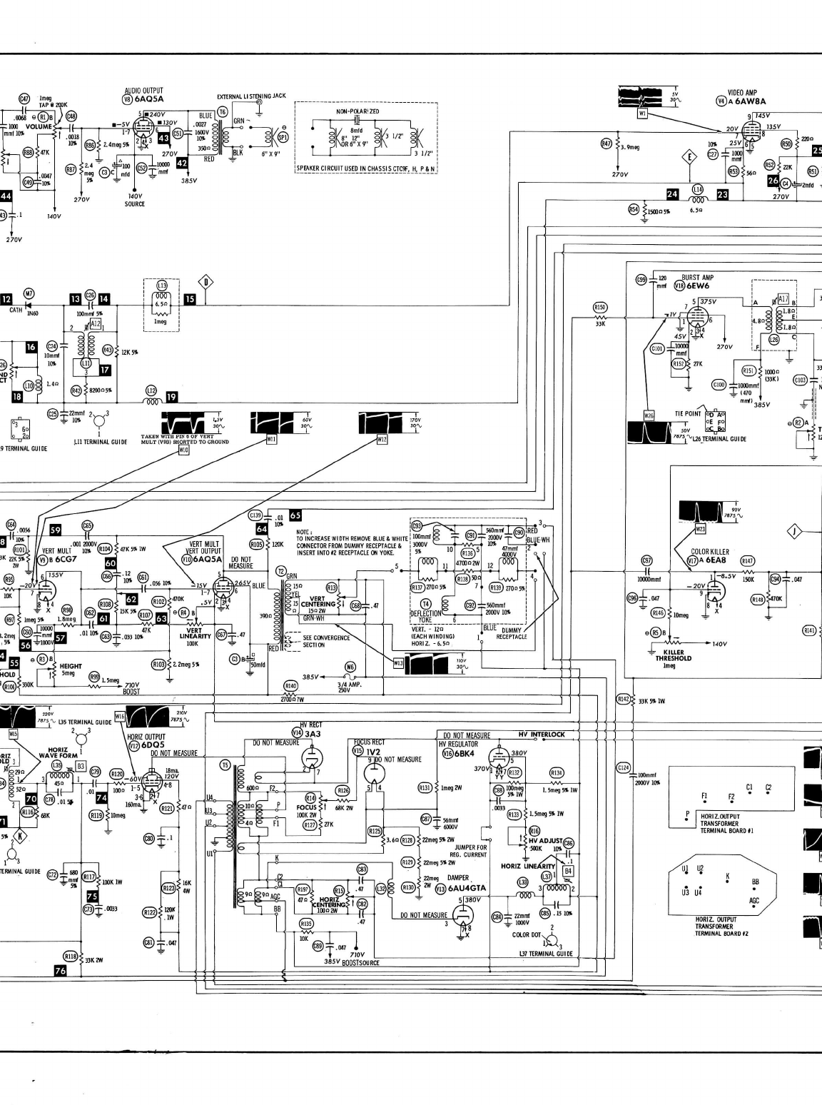
Adjust
the
Horizontal
Waveform
slug (B3)
for
waveform
similar
to
Fig.11
with
the
round
and
sharppeaks
at
equal
amplitudes.
Keep
the
picture
in
syncduring
this
adjustment
with
the
HorizontalHold.
-
Adjust
the
HorizontalLinearityslug(B4)
for
MINIMUM
currentindication
on
the
500MA
meter.
Adjust
the
High
Voltage
Adjust
for23.
5KV
onthe
VTVM.
Check
the
cur-
rentreading
onthe
meter.
It
should
not
exceed
. 8MA(19
watts).
AGC
ADJUSTMENT
Tune
inthe
strongest
signal
inthe
area.
Connect
the
high
side
ofa
scope
to
point
<£>
. Low
side
to
chassis.
Adjust
theAGC
control
for10
volts
peak
to
peak
onthe
scope.
NOISE
INVERTER
ADJUSTMENT
Connect
the
Vertical
amplifier
ofthe
scope
to
point
<£>
. Low
side
to
chassis.
Turn
the
Noisecontrol
fully
counterclockwise.Turnslowly
clockwise
whileobserving
the
scope,
when
the
tips
ofthe
syncpulses
ap-
pear
tobe
clipped,back
off
until
the
clipping
just
disappears.
COLOR
AFC
ALIGNMENT
Connect
the
Verticalamplifier
ofthe
scope
to
point
<@>
. Low
side
to
chassis.
Connect
theDC
probe
ofthe
VTVM
thru
a
470K
resistor
topin
2
(plate)
of
Chroma
Sync
Phase
Detector.
Common
to
chassis.
Setthe
Tint
control
tothe
center
ofits
range.
Turn
the
Killer
Threshold
control
fully
counterclockwise.
Connect
a
short
clipfrompoint
<^y
to
chassis.
Adjust
A16
for
maximumdeflection
onthe
VTVM.
Ifthe
ChromaReference
Oscillator
isnot
running,
no
readingwill
be
obtained.
In
which
case
ad-
just
AlS.just
enough
to
start
the
oscillator
and
then
adjust
A16.
Adjust
A17
for
maximumdeflection
onthe
VTVM.
Make
sure
the
oscillator
is
running
and
locked
in.
Connect
a
clip
leadfrompoint
<@>
to
chassis.
Disconnect
the
VTVM.
Ad-
just
A18
until
the
Color
bars
stand
sUU
onthe
screen
or
drift
slowly
by.
Move
the
scopeconnection
to
point<^
.
Remove
the
cliplead
from
point
<§>
.
Observe
thebar
pattern
onthe
scope
and
retouch
A17
if
necessary
to
obtainproperresponsecurve
simi-
lartoR-Yin
Fig.
12
withequalchange
when
rotating
the
Tintcontrolfrom
one
endtothe
other.
After
this
adjustment
return
the
Tintcontrol
the
nominalsetting.
Move
the
scope
connection
to
point
<g>
. If
necessary,
retouch
A16
for
proper
B-Y
signal
as
shown
in
Fig.
12.
Move
scopeconnection
to
point
<(§>
.
Check
for
proper
G-Y
signal
andre-
peat
adjustment
of
A17,
A16
if
necessary.
Remove
all
clip
leads
and
test
equipment.Switch
toan
unused
channel
and
adjust
the
KillerThresholdcontrol
tothe
point
where
color
justdisappears
from
the
noisepattern
onthe
screen.
PRELIMINARY
CONVERGENCE
ADJUSTMENTS
Connect
the
output
ofa
white
dot
generator
tothe
antenna
terminals.
Pre-
setall
Red,Green
and
BlueHorizontal
and
Vertical
Convergence
controls
and
coils
tothe
center
of
theirranges.
Adjust
Red,Green
and
BlueConvergencemagnets
andthe
Lateral
Magnet
to
produce
a
white
dotinthe
center
ofthe
screen.
Keep
the
screen
in
sharp
focus
duringthis
adjustment.
Switch
the
generator
to
standby
posi-
tion.
COLOR
PURITY
ADJUSTMENTS
If
necessary,demagetizepicturetube
and
associated
components.
Setthered
tabs
ofthe
Purity
Magnet
together.
Setthe
Edge
Purity
Mag-
nets
so
that
thetwo
magnets
areinthe
same
relative
position
one
above
the
other.Loosen
the
yoke
clamp
and
slide
the
deflection
yoke
tothe
rear
as
faras
possible^
Shunt
test
points
^y
and
<£J>to
chassis
thruindividual100K
resistors.
Slide
PurityMagnet
aroundthe
neck
ofthe
picturetube
andatthe
same
timespread
thered
tabsapart
to
produce
a
uniform
red
screen
area
at
the
center
ofthe
screen.
Move
the
Yoke
forward
and
adjust
for
best
overall
red
screen
without
neck
shadow.
Adjust
so
that
any
colorimpuritiesoccur
atthe
extreme
edges
ofthe
screen.
Adjust
the
Screen
controls
fora
white
raster
and
adjust
the
Edge
Purity
Magnets
for
best
edgepurity.Maximumcorrection
is
obtained
with
the
open
ends
ofthe
magnets
180
degrees
apart.
Rotatebothmagnets
simul-
taneously
to
achieve
the
desired
results.
VERTICAL
CONVERGENCE
ADJUSTMENTS
Recheck
the
"Preliminary
ConvergenceAdjustments"
for
correct
setting
of
the
Red,Green
and
Bluemagnets
andthe
Lateral
Magnet
to
produce
a
white
dotinthe
center
ofthe
screen.
Loosen
thetwo
screws
holding
the
Convergence
board,
slide
the
board
to
the
left
and
remove.
Fasten
the
board
tothetop
rail
ofthe
cabinetwith
the
two
screws
provided.
Place
so
that
the
controls
faceforward.
Switch
thedot
generator
to
vertical
bars
and
adjust
theRedand
Green
tilt
controls
for
equaldisplacement
ofthe
Center
baratthetopand
bottom.
Adjust
theRedand
GreenAmplitudecontrolsuntil
theredand
green
lines
are
straight.
Graduallyreduce
the
Amplitudes
to
converge
the
red,green
and
bluealong
the
center
lines,
retouching
theRedand
Green
Tilt
controls
to
keep
the
lines
parallel.
The
centerlineshouldconverge
to
produce
a
white
linefrom
topto
bottom
or
show
slight
displacement
oftheRedonone
side
andthe
green
onthe
other
with
all
three
parallel
from
topto
bottom.
Readjust
the
ConvergenceMagnets
If
necessary
to
superimpose
the
three
parallel
lines
to
produce
a
singlewhitelinefrom
topto
bottom.
Switch
the
generator
to
horizontal
bars.
Referring
tothetopand
bottom
bars
asa
reference,adjust
the
Blue
Vertical
Tilt
and
Amplitude
controls
for
equal
downward
displacement
ofthe
bluehorizontal
from
the
extreme
top
and
bottom
lines
ofthe
raster.
Reduce
the
Blue
Vertical
Amplitude
control
to
converge
all the
lines
at the
center,
retouching
the
Blue
Vertical
tilt
SLIGHTLY,
if
necessary
making
all
lines
white
atthe
centerfrom
top
to
bottom.
HORIZONTAL
CONVERGENCE
ADJUSTMENTS
Switch
the
generator
to
Crosshatchpattern.
If
necessary,retouchcon-
vergencemagnets
to
producegoodconvergence
atthe
center
ofthe
screen.
Adjust
coil
B-l
so
that
the
bluehorizontalline
atthe
rightcenter
ofthe
screen
isa
straight
line.
Adjust
control
B-2fora
straight
blueline
tothe
left
ofthe
raster.
Ad-
just
R-G-1
to
make
the
vertical
lines
atthe
right
side
ofthe
raster
con-
verge.
Adjust
R-G-2
to
make
the
horizontal
redand
green
lines
atthe
right
side
ofthe
screen
converge.Readjust
B-lto
make
the
blue
lines
at
the
right
centerfall
ontheredand
greenconverged
lines.
Retouch
R-G-1
for
convergence
ofthe
vertical
lines
atthe
right
side.
Adjust
control
R-G-3
to
make
the
vertical
lines
atthe
left
side
con-
verge.
Adjust
control
R-G-4
to
make
theredand
greenhorizontal
lines
atthe
left
side
ofthe
screen
converge.
Readjust
B-2to
make
the
blue
lines
atthe
left
centerfall
onthe
converged
redand
green
lines.
The
picture
or
patternshould
now
show
properconvergenceover
theen-
tire
screen.
GRAY
SCALE
ADJUSTMENTS
Set
Green
and
BlueScreen
controls
two-thirds
clockwisefromminimum.
Set
the
Green
and
BlueBackground
controls
tothe
center
of
their
ranges.
SettheRed
Backgroundcontrol
fully
counterclockwise
anddonot
change
it
from
this
point
on.
Tune
ina
station
and
then
turn
the
Brightness
and
Contrastcontrols
fully
counterclockwise.
Usea
program
which
displays
the
full
range
of
contrast
conditionsfrom
high
lights
tolow
lights.
Advance
the
Brightnesscontrol
to
obtain
a
picture
of
normalbrightness.
The
control
willusuallyfallapproximately
two-thirds
clockwise.
DONOT
overload.
Adjust
the
Blue
and
GreenBackground
controls
to
producewhite
inthe
highlight
areas
ofthe
picture.
Reduce
the
Brightness
to
produce
a low
level
brightness
picture
and
ob-
serve
the
lowlight
areas
(darkobjects)
ofthe
picture.Some
color
will
prevail
inthe
lowlight
areas,
as
indicatedbelow.
1.
Yellow
inthe
lowlight
areas.
BlueScreenmust
be
turned
clockwise.
2.
Magenta
inthe
lowlight
areas.
GreenScreenmust
be
turned
clockwise.
3.Redinthe
lowlight
areas.
Blue
and
GreenScreensmust
be
turned
clockwise.
4.
Green
inthe
lowlight
areas.
Green
screen
must
be
turned
counterclockwise.
5.
Blue
inthe
lowlight
areas.
Blue
Screenmust
be
turnedcoun-
terclockwise.
6.
Cyan
inthe
lowlight
areas.
Blue
and
GreenScreensmust
be
turned
counterclockwise.
Depending
upon
which
ofthe
aboveconditionsprevail,turn
the
appro-
priate
control
inthe
indicateddirectionuntil
a
graypicture
is
obtained,
then
SLIGHTLYbeyond
inthe
same
direction.
Advance
the
Brightnesscontrol
to
produce
a
well
lit
picture.
Adjust
the
Blue
and
GreenBackground
controlsforwhite
inthe
highlight
areas
of
the
picture.
DONOT
ADJUST
THERED
BACKGROUND
CONTROL.
Re-
turn
the
Brightnesscontrol
tothe
lowlight
area
and
retouch
the
proper
Screencontrols
for
gray
inthe
lowlight
areas.
Check
for
propertracking
atall
light
levels
and
retouch
as
necessary
being
sure
notto
change
Red
Backgroundcontrolsetting.
PAGE
6