RCF DXT 9000 User manual

TABLE OF CONTENTS
INDICE
ENGLISH
SAFETY PRECAUTIONS
DESCRIPTION
FRONT PANEL AND HANDHELD MICROPHONE
INTERNAL BOARD CONNECTIONS
SYSTEM CONNECTIONS
SPECIFICATIONS
ITALIANO
AVVERTENZE PER LA SICUREZZA
DESCRIZIONE
PANNELLO FRONTALE E MICROFONO PALMARE
COLLEGAMENTI ALLA SCHEDA INTERNA DELLA CONSOLLE
COLLEGAMENTI AL SISTEMA
DATI TECNICI
4
5
6
7
9
10
12
13
14
15
17
18
www.acornfiresecurity.com

4
ENGLISH
IMPORTANT NOTES
Before connecting and using this console, please read this instruction manual carefully and keep
it on hand for future reference. The manual is to be considered an integral part of this product and
must accompany it when changing ownership as a reference for correct installation and use as
well as for the safety precautions. RCF S.p.A. will not assume any responsibility for the incorrect
installation and / or use of this product.
SAFETY PRECAUTIONS
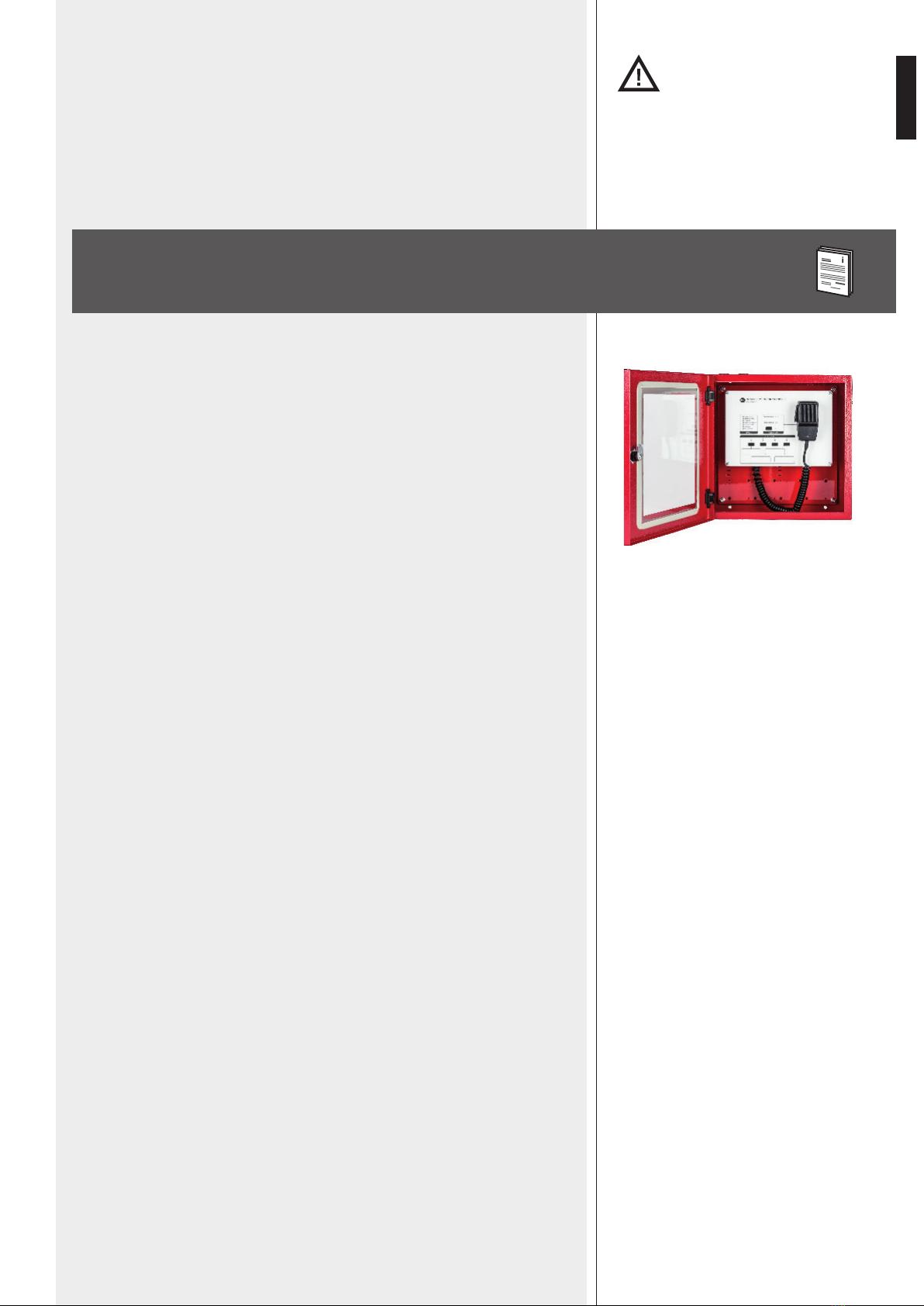
1. According to EN 54-16 standard, paging microphones shall be only accessible by persons
having a specic responsibility for safety and who are trained and authorized to operate in the
following conditions: quiescent, voice alarm, fault warning and disablement.
2. All the precautions, in particular the safety ones, must be read with special attention, as they
provide important information.
3. Make sure all connections have been made correctly before switching all devices on.
Do not connect / disconnect this console when the system is operating.
4. Protect console cables from damage and assure they are positioned where these cannot be
stepped on or crushed by objects.
5. Do not put this console into water (or another liquid), do not throw it.
6. Never attempt to carry out any operations, modications or repairs.
If the console does not work properly, contact your authorized service centre.
7. Should the console emit any strange odour or even smoke, turn the sound system off
immediately and disconnect it.
8. RCF S.p.A. strongly recommends the sound system installation is only made by professional
qualied installers (or specialised rms), who can certify it according to the regulations in force.
The entire audio system must comply with the current standards and regulations regarding
electrical systems.
9. Mechanical and electrical factors need to be considered when installing a professional audio
system (in addition to those which are strictly acoustic, such as sound pressure, angles of
coverage, frequency response, etc.).
10. Do not point the microphone at near loudspeakers, in order to avoid feedback.
11. Hearing loss
Exposure to high sound levels can cause permanent hearing loss. The acoustic pressure level that
leads to hearing loss is different from person to person and depends on the duration of exposure.
To prevent potentially dangerous exposure to high levels of acoustic pressure, anyone who is
exposed to these levels should use adequate protection devices.
When a transducer capable of producing high sound levels is being used, it is necessary to wear
ear plugs or protective earphones.
12. To prevent inductive effects from causing hum, noise and a bad system operating, microphone
cables should not be laid together with other electric cables (mains) and loudspeaker lines.
13. Keep the console far from any excessive heat source.
14. Do not use solvents, alcohol, benzene or other volatile substances for cleaning the external
parts. Just use a dry cloth.
IMPORTANT NOTES
SAFETY PRECAUTIONS
www.acornfiresecurity.com

5
ENGLISH
DESCRIPTION
IN 9000 is an emergency reman console designed to be interfaced with the RCF DXT
9000 evacuation system, in order to provide an analogue backup solution for emergency
communications, in case of interruption of the main digital connection RCFBUS.
This console is protected by a wall-mounted red metallic box with glass and equipped with
a monitored handheld microphone having a momentary ‘Push-To-Talk’ (PTT) button.
The PTT command is also available as front panel button, together with a VU-meter LED
bar (microphone signal level) and an ‘IN USE’ LED.
IN 9000 needs an external 24 ÷ 48 V dc power supply EN54-4 providing at least 20W
output power. Moreover, a monitored GPI is provided to report any power supply fault.
The audio output can be distributed up to 64 DXT 9000 units and routed to 4 independent
lines selectable on the console front panel.
A dedicated (optional) RCF OT 3500 audio transformer can be installed on each output
line.
MAIN FEATURES
-Monitored reman’s microphone with PTT button.
-The console is protected by a wall-mounted red metallic box with glass.
-Fully analogue connection (in the event of interruption of RCF BUS).
-Output signal can be sent to max. 64 DXT 9000 units over 4 selectable independent
lines.
-2 monitored GPI (‘General Purpose Input’): power supply and DXT 9000 fault.
-1 monitored GPO (‘General Purpose Output’) to report a console fault to DXT 9000.
-Power supply range 24 ÷ 48 V dc (external 20 W power supply required).
-Front panel fault reporting: general, microphone, command port, power supply, power
supply GPI, DXT general, DXT general GPI.
IMPORTANT NOTES
IN 9000 shall be placed in a room with access restricted to authorized
personnel only, within a protected area not subjected to conditions that may
affect its operation, for example: moisture, salt, water inltration, extreme
temperatures, shocks, etc.
It should be placed at a height from the oor that makes it easily accessible.
Also check the suitability of the wall and the components used for attachment (wall plugs,
screws, not supplied by RCF), which must guarantee the system security over time, also
considering, for example, the mechanical vibrations normally generated by transducers.
RCF S.P.A. THANKS YOU FOR PURCHASING THIS PRODUCT, WHICH HAS BEEN
DESIGNED TO GUARANTEE RELIABILITY AND HIGH PERFORMANCES.
WARNING:
Any change made by unauthorized personnel to the product and / or the
system (in which it is installed and congured, including rack cabinet and
wiring) may invalidate the CE marking (certication EN54-16: 2008) and also
the product warranty.
www.acornfiresecurity.com

6
ENGLISH
1IN USE LED When lit: the console is being used.
2LEVEL LED bar indicating the microphone signal level.
3PTT (‘Push To Talk’) button: push and hold down to turn the microphone on and
page the areas assigned to the output lines A, B, C, D, previously selected by pushing
the respective buttons 4.
4OUTPUT LINES A-B-C-D buttons with LEDs: push to toggle on/off the respective
output lines.
5The rectangles graphically linked to the OUTPUT LINES A, B, C, and D can be used
to add labels aimed at better identifying them.
HANDHELD MICROPHONE
The handheld microphone momentary push button has the same function of the front
panel PTT button 3.
FAULT LEDs
LABEL DESCRIPTION
6GENERAL Console local general fault
7MICROPHONE Console microphone fault
8COMMAND PORT Command port fault (no monitoring 24 V dc)
9POWER SUPPLY External power supply fault (monitored GPI)
10 POWER SUPPLY GPI IN 9000 internal fault on its 'Power Supply Fault' GPI
11 DXT GENERAL DXT 9000 general fault (monitored GPI)
12 DXT GENERAL GPI IN 9000 internal fault on its 'DXT 9000 General Fault' GPI
1
4
5
6
7
8
9
10
11
12
2
3
FRONT PANEL AND HANDHELD MICROPHONE
www.acornfiresecurity.com

7
ENGLISH
INTERNAL BOARD CONNECTIONS
-Connect the IN 9000 POWER SUPPLY INPUT 13 to the external EN 54-4 power
supply output (24 ÷ 48 V dc, 20 W). Pay attention to its polarity.
-Connect the IN 9000 ‘POWER SUPPLY FAULT’ MONITORED GPI 14 to the external
power supply GPO (for remote fault monitoring).
-Connect a DXT 9000 unit monitored GPO to the IN 9000 ‘DXT 9000 GENERAL
FAULT’ MONITORED GPI 15 .
-Connect the ‘IN 9000 FAULT’ GPO 16 to a DXT 9000 unit monitored GPI (1÷8).
POWER SUPPLY 24V ÷ 48VDC
POWER SUPPLY FAULT (MONITORED GPI)
DXT 9000 GENERAL FAULT (MONITORED GPI)
IN 9000 FAULT (GPO)
LINE A LINE CLINE B
OUTPUT LINES
LINE D
13
14
15
16
17
www.acornfiresecurity.com

8
ENGLISH
-Connect IN 9000 output lines 17 to FALLBACK inputs of DXT 9000 units, as shown
in the following gure (audio: + hot, – cold, ground; command: CM–, CM+)
Note: if ot 3500 traNsformers are Not required oN the output liNes, the correspoNdiNg
from / to coNtacts shall be shorted (factory settiNg).
-If an OT 3500 transformer is necessary on an output line due to excessive noise,
connect it (pin to pin) as shown in the next gure.
LINE A
LINE A
www.acornfiresecurity.com

9
ENGLISH
SYSTEM CONNECTIONS
IN 9000 can be connected to several rack cabinets (including DXT 9000 main units
and ampliers), routing its audio output through max. 4 independent lines.
For example, next 2 gures show 2 possible wirings: the former 1is the most
simple one (using only one output line), the latter 2is the most complex one
(using all the 4 output lines).
Of course, any layout in between is possible, depending on installation
requirements.
1 2
www.acornfiresecurity.com

10
ENGLISH
SPECIFICATIONS
Microphone type:
Mic. polar patter:
Output impedance:
Microphone sensitivity:
Frequency response:
Box dimensions:
Net weight:
dynamic
omnidirectional
500 Ω ± 30% (1 kHz)
– 70 dB ± 3 dB (0 dB=1V/μbar, 1 kHz)
300 Hz ÷ 6 kHz (– 3 dB)
360 x 360 x 129 mm
7 kg
www.acornfiresecurity.com

12
ITALIANO
IMPORTANTE
Prima di collegare ed utilizzare questa consolle, leggere attentamente le istruzioni contenute in
questo manuale, il quale è da conservare per riferimenti futuri.
Il presente manuale costituisce parte integrante del prodotto e deve accompagnare quest’ultimo
anche nei passaggi di proprietà, per permettere al nuovo proprietario di conoscere le modalità
d’installazione e d’utilizzo e le avvertenze per la sicurezza.
L’installazione e l’utilizzo errati del prodotto esimono RCF S.p.A. da ogni responsabilità.
AVVERTENZE PER LA SICUREZZA
1. Secondo la norma EN 54-16 standard, i microfoni per annunci devono essere accessibili
solo alle persone aventi una funzione specica in materia di sicurezza e che sono addestrate
ed autorizzate ad operare nelle seguenti condizioni: in attesa, durante un allarme vocale, su
segnalazione di guasto e disattivazione.
2. Tutte le avvertenze, in particolare quelle relative alla sicurezza, devono essere lette con
particolare attenzione, in quanto contengono importanti informazioni.
3. Prima di accendere le apparecchiature, assicurarsi che tutte le connessioni siano corrette.
Non collegare / scollegare questa consolle quando il sistema è acceso.
4. Accertarsi che i cavi della consolle non possano essere calpestati o schiacciati da oggetti, al
ne di salvaguardarne l’integrità.
5. Non immergere la consolle nell’acqua (od in altri liquidi), non lanciarla o lasciarla cadere.
6. Non eseguire sulla consolle interventi / modiche / riparazioni; contattare i centri di assistenza
autorizzati nel caso che non funzioni correttamente.
7. Nel caso che dalla consolle provengano stranamente odori anomali od addirittura fumo,
spegnere immediatamente il sistema audio e scollegarla.
8. RCF S.p.A. raccomanda vivamente che l’installazione del sistema audio sia eseguita solamente
da installatori professionali qualicati (oppure da ditte specializzate) in grado di farla correttamente
e certicarla in accordo con le normative vigenti. Tutto il sistema audio dovrà essere in conformità
con le norme e le leggi vigenti in materia di impianti elettrici.
9. I fattori meccanici ed elettrici sono da considerare quando si installa un sistema audio
professionale (oltre a quelli prettamente acustici, come la pressione sonora, gli angoli di copertura,
la risposta in frequenza, ecc.).
10. Non puntare il microfono verso un diffusore acustico vicino, onde evitare un possibile innesco.
11. Perdita dell’udito
L’esposizione ad elevati livelli sonori può provocare la perdita permanente dell’udito. Il livello di
pressione acustica pericolosa per l’udito varia sensibilmente da persona a persona e dipende dalla
durata dell’esposizione. Per evitare un’esposizione potenzialmente pericolosa ad elevati livelli di
pressione acustica, è necessario che chiunque sia sottoposto a tali livelli utilizzi delle adeguate
protezioni; quando si fa funzionare un trasduttore in grado di produrre elevati livelli sonori, è
necessario indossare dei tappi per orecchie o delle cufe protettive.
12. Per evitare che fenomeni induttivi diano luogo a ronzii, disturbi e compromettano il buon
funzionamento dell’impianto, i conduttori del segnale audio non devono essere canalizzati
insieme a quelli dell’energia elettrica e/o alle linee dei diffusori acustici.
13. Collocare la consolle lontano da amme (o fonti di calore eccessivo).
14. Non usare solventi, alcool, benzina o altre sostanze volatili per la pulitura delle parti esterne,
ma un panno asciutto.
IMPORTANTE
AVVERTENZE PER LA SICUREZZA
www.acornfiresecurity.com

13
ITALIANO
DESCRIZIONE
IN 9000 è una consolle d’emergenza (per vigili del fuoco) per il sistema DXT 9000, con
collegamento analogico, che permette sempre la diffusione di un annuncio anche nel caso
di interruzione del bus digitale del sistema.
La consolle è protetta all’interno di una cassetta metallica (di colore rosso) con vetro ed è
dotata di un microfono dinamico palmare con tasto di attivazione “PTT” (“Push To Talk”:
“premere per parlare”).
Il tasto PTT è disponibile anche sul pannello frontale, dove vi sono inoltre una barra a LED
per il livello del segnale microfonico ed un LED “IN USE” (in uso).
IN 9000 necessita di un alimentatore esterno 24 ÷ 48 V c.c. conforme alla norma EN54-4,
avente una potenza d’uscita di almeno 20W; inoltre, è disponibile un ingresso logico (GPI)
monitorato per la ricezione del segnale di guasto dell’alimentatore.
L’uscita audio può essere inviata ad un massimo di 64 unità del sistema DXT 9000 tramite
le sue 4 linee indipendenti selezionabili sul pannello frontale.
Su ciascuna linea è possibile inserire un trasformatore RCF OT 3500 (dedicato per segnali
audio).
CARATTERISTICHE PRINCIPALI
-Microfono palmare monitorato per vigili del fuoco.
-La consolle è protetta all’interno di una cassetta metallica rossa con vetro.
-Collegamento interamente analogico (nel caso di interruzione del bus digitale del
sistema).
-Segnale d’uscita inviabile a max. 64 unità DXT 9000 tramite 4 linee indipendenti e
selezionabili.
-2 ingresso logici (GPI) monitorati: alimentazione e guasto al sistema DXT 9000.
-1 uscita logica (GPO) monitorata per la segnalazione di guasto della console al sistema
DXT 9000.
-Alimentazione richiesta: da 24 a 48 V c.c.; è necessario un alimentatore esterno avente
potenza nominale di almeno 20W.
-Indicazioni guasto su pannello frontale: generale, microfono, comandi, alimentazione,
ingresso logico guasto alimentazione, sistema DXT, ingresso logico sistema DXT.
NOTE IMPORTANTI
IN 9000 deve essere posta in un locale con accesso riservato al solo
personale autorizzato, installata a parete in un ambiente chiuso, all’interno
di un’area protetta non soggetta a condizioni che possano compromettere
le sue prestazioni, ad esempio: umidità, salsedine, inltrazioni d’acqua,
temperature estreme, possibilità di urti, ecc. .
È consigliabile posizionarla ad un’altezza dal pavimento che la renda facilmente accessibile.
Vericare inoltre l’idoneità della parete e dei componenti utilizzati per il ssaggio (tasselli
e viti non forniti da RCF) che devono garantire la sicurezza del sistema nel tempo, anche
considerando, ad esempio, vibrazioni meccaniche normalmente generate da un trasduttore.
RCF S.P.A. VI RINGRAZIA PER L’ACQUISTO DI QUESTO PRODOTTO, REALIZZATO
IN MODO DA GARANTIRNE L’AFFIDABILITÀ E PRESTAZIONI ELEVATE.
ATTENZIONE:
Ogni modica eseguita da personale non autorizzato al prodotto e/o al
sistema (in cui è installato e congurato, armadio rack e cablaggi inclusi) può
far decadere la marcatura CE (certicazione EN54-16:2008) e la garanzia del
prodotto medesimo.
www.acornfiresecurity.com

14
ITALIANO
1IN USE LED (se acceso): la consolle è in uso.
2LEVEL Barra LED indicante il livello audio del microfono.
3PTT (tasto): premere e tener premuto per attivare il microfono ed effettuare
un annuncio verso le aree assegnate alle linee d'uscita A, B, C, D (precedentemente
selezionate tramite i rispettivi tasti 4).
4OUTPUT LINES A-B-C-D: premere questi tasti per attivare o disattivare le
rispettive linee d'uscita.
5Spazi rettangolari collegati gracamente alle uscite A, B, C, D, utilizzabili per
apporvi delle etichette adesive utili per l'identicazione delle aree selezionate.
MICROFONO PALMARE
Il tasto di attivazione del microfono palmare ha la stessa funzione del tasto PTT 3del
panello frontale.
LED SEGNALAZIONE GUASTI
NOME DESCRIZIONE
6GENERAL Guasto generico della consolle
7MICROPHONE Guasto al microfono della consolle
8COMMAND PORT Guasto alle porte comandi (manca alimentazione monitoraggio)
9POWER SUPPLY Segnalazione remota guasto alimentatore esterno (tramite GPI)
10 POWER SUPPLY GPI Guasto interno (IN 9000) al GPI “Power Supply Fault”
11 DXT GENERAL Segnalazione remota guasto DXT 9000 (tramite GPI)
12 DXT GENERAL GPI Guasto interno (IN 9000) al GPI “DXT 9000 General Fault”
1
4
5
6
7
8
9
10
11
12
2
3
PANNELLO FRONTALE E MICROFONO PALMARE
www.acornfiresecurity.com

15
ITALIANO
COLLEGAMENTI ALLA SCHEDA INTERNA DELLA CONSOLLE
-Collegare l'ingresso per l'alimentazione IN 9000 POWER SUPPLY INPUT 13
all'alimentatore esterno EN 54-4 (24 ÷ 48 V c.c., 20 W); prestare attenzione alla
polarità.
-Collegare l'ingresso logico (GPI) monitorato POWER SUPPLY FAULT 14 (della
consolle IN 9000) all'uscita logica dell'alimentatore esterno per la sua segnalazione
di guasto.
-Collegare un'uscita logica monitorata (MONITORED GPO) di un'unità del sistema
DXT 9000 all'ingresso logico monitorato DXT 9000 GENERAL FAULT (MONITORED
GPI) 15 della consolle IN 9000.
-Collegare l’uscita logica FAULT GPO 16 (della consolle IN 9000) ad un ingresso
logico monitorato (MONITORED GPI, 1÷8) di un’unità del sistema DXT 9000.
POWER SUPPLY 24V ÷ 48VDC
POWER SUPPLY FAULT (MONITORED GPI)
DXT 9000 GENERAL FAULT (MONITORED GPI)
IN 9000 FAULT (GPO)
LINE A LINE CLINE B
OUTPUT LINES
LINE D
13
14
15
16
17
www.acornfiresecurity.com

16
ITALIANO
-Collegare le linee d'uscita 17 della consolle IN 9000 agli ingressi FALLBACK delle
unità del sistema DXT 9000, come mostrato nella gura seguente (audio: + positivo,
– negativo, massa; comando: CM–, CM+)
Nota: se itrasformatori ot 3500 NoN soNo richiesti sulle liNee d'uscita, icoNtatti
corrispoNdeNti from (da) / to (a) devoNo essere cortocircuitati (impostazioNe di fabbrica).
-Se un trasformatore OT 3500 è necessario su una linea d’uscita a causa di rumore
eccessivo, collegarlo come mostrato nella gura seguente.
LINE A
LINE A
www.acornfiresecurity.com

17
ITALIANO
COLLEGAMENTI AL SISTEMA
La console IN 9000 può essere collegata a diversi armadi (rack cabinet) che
includono unità centrali ed amplicatori del sistema DXT 9000, inviando la sua
uscita audio tramite max. 4 linee indipendenti.
Ad esempio, le successive 2 gure mostrano 2 possibili cablaggi: il primo 1è
il più semplice ed usa una sola linea d'uscita, il secondo 2è il più complesso e
le usa tutte e quattro; ovviamente, è possibile qualsiasi disposizione intermedia a
seconda dell'installazione.
1 2
www.acornfiresecurity.com

18
ITALIANO
DATI TECNICI
Tipo microfono:
Direttività microfono:
Impedenza d’uscita:
Sensibilità microfono:
Risposta in frequenza:
Dimensioni cassetta:
Peso netto:
dinamico
omnidirezionale
500 Ω ± 30% (1 kHz)
– 70 dB ± 3 dB (0 dB=1V/μbar, 1 kHz)
300 Hz ÷ 6 kHz (– 3 dB)
360 x 360 x 129 mm
7 kg
www.acornfiresecurity.com
This manual suits for next models
1
Table of contents
Languages:
Other RCF Music Mixer manuals