RCF MQ 50i-W User manual

the rules of sound
MQ
50i-W
MQ
50i-S
User manual
User manual
User manual
Manuale d’uso
Manuale d’uso
Manuale d’uso
WALL FLUSH-MOUNTING CONTROLLED DIRECTIVITY
MONITOR LOUDSPEAKERS
DIFFUSORI MONITOR A DIRETTIVITÀ CONTROLLATA PER
INSTALLAZIONE AD INCASSO A PARETE


3
ITALIANO
Prima di collegare ed utilizzare questo prodotto, leggere attentamente le istruzioni contenute in
questo manuale, il quale è da conservare per riferimenti futuri. Il presente manuale costituisce parte
integrante del prodotto e deve accompagnare quest’ultimo anche nei passaggi di proprietà, per
permettere al nuovo proprietario di conoscere le modalità d’installazione e d’utilizzo e le avvertenze
per la sicurezza.
L’installazione e l’utilizzo errati del prodotto esimono la RCF S.p.A. da ogni responsabilità.
ITALIANO
ATTENZIONE: Per prevenire i rischi di fiamme o scosse elettriche, non esporre il diffusore alla
pioggia o all’umidità ed alle polveri, salvo il caso in cui questo sia stato espressamente progettato
e costruito con un grado di protezione IP adeguato (evidenziato nella documentazione tecnica del
dispositivo).
AVVERTENZE PER LA SICUREZZA
1. Tutte le avvertenze, in particolare quelle relative alla sicurezza, devono essere lette con
particolare attenzione, in quanto contengono importanti informazioni.
2. La linea diffusori (uscita dell’amplificatore) può avere una tensione sufficientemente alta (es. 100 V)
da costituire un rischio di folgorazione per le persone: non procedere mai all’installazione o alla
connessione del diffusore quando la linea diffusori è in tensione.
3. Assicurarsi che tutte le connessioni siano corrette e che la tensione d’ingresso (in un sistema a
tensione costante) oppure l’impedenza del diffusore sia compatibile con le caratteristiche d’uscita
dell’amplificatore.
4. Accertarsi che la linea diffusori non possa essere calpestata o schiacciata da oggetti, al fine di
salvaguardarne la perfetta integrità.
5. Impedire che oggetti o liquidi entrino all’interno del prodotto, perché potrebbero causare un
corto circuito.
6. Non eseguire sul prodotto interventi / modifiche / riparazioni se non quelle espressamente
descritte sul manuale istruzioni.
Contattare centri di assistenza autorizzati o personale altamente qualificato quando:
•Il diffusore non funziona (o funziona in modo anomalo);
• il cavo è danneggiato;
• oggetti o liquidi sono entrati nel diffusore;
• il diffusore non è più integro (a causa di urti / incendio).
7. Nel caso che dal diffusore provengano odori anomali o fumo, togliere immediatamente la
tensione dalla linea diffusori e poi scollegare il diffusore.
8. Non collegare a questo diffusore apparecchi ed accessori non previsti.
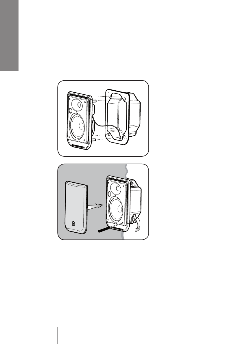
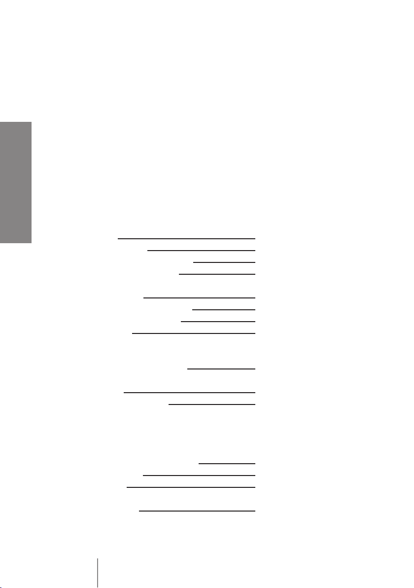
Quando è prevista l’installazione sospesa, utilizzare solamente gli appositi punti di ancoraggio e
non cercare di appendere il diffusore con elementi non idonei o previsti allo scopo.
Verificare inoltre l’idoneità del supporto (parete, soffitto, struttura ecc.) e dei componenti utilizzati
per il fissaggio (tasselli, viti, staffe non fornite da RCF ecc.) che devono garantire la sicurezza
dell’impianto / installazione nel tempo, anche considerando, ad esempio, vibrazioni meccaniche
normalmente generate da un trasduttore.
9. La RCF S.p.A. raccomanda vivamente che l’installazione di questo prodotto sia eseguita
solamente da installatori professionali qualicati (oppure da ditte specializzate) in grado di
farla correttamente e certicarla in accordo con le normative vigenti.
Tutto il sistema audio dovrà essere in conformità con le norme e le leggi vigenti in materia di
impianti elettrici.
10. Vi sono numerosi fattori meccanici ed elettrici da considerare quando si installa un sistema
audio professionale (oltre a quelli prettamente acustici, come la pressione sonora, gli angoli di
copertura, la risposta in frequenza, ecc.).
IMPORTANTE

4
ITALIANO
11. PERDITA DELL’UDITO
L’esposizione ad elevati livelli sonori può provocare la perdita permanente dell’udito. Il livello di
pressione acustica pericolosa per l’udito varia sensibilmente da persona a persona e dipende dalla
durata dell’esposizione. Per evitare un’esposizione potenzialmente pericolosa ad elevati livelli di
pressione acustica, è necessario che chiunque sia sottoposto a tali livelli utilizzi delle adeguate
protezioni; quando si fa funzionare un trasduttore in grado di produrre elevati livelli sonori è
necessario indossare dei tappi per orecchie o delle cuffie protettive.
Consultare i dati tecnici contenuti nel manuale istruzioni per conoscere la massima pressione sonora
che il diffusore acustico è in grado di produrre.
12. I diffusori devono essere collegati in fase (corrispondenza delle polarità +/- tra amplificatori e
diffusori) in modo da garantire una corretta riproduzione audio, soprattutto quando i diffusori sono
collocati in posizione fra loro adiacente o nello stesso ambiente.
13. Per evitare che fenomeni induttivi diano luogo a ronzii, disturbi e compromettano il buon
funzionamento dell’impianto, le linee diffusori non devono essere canalizzate insieme ai conduttori
dell’energia elettrica, ai cavi microfonici, alle linee di segnale a basso livello che fanno capo ad
amplificatori.
14. Il cavo per il collegamento del diffusore dovrà avere conduttori di sezione adeguata
(possibilmente intrecciati, per minimizzare gli effetti induttivi dovuti all’accoppiamento con campi
elettro-magnetici circostanti) ed un isolamento idoneo.
PRECAUZIONI D’USO
• Collocare il diffusore lontano da fonti di calore.
• Non forzare mai gli organi di comando (tasti, manopole ecc.).
• Non usare solventi, alcool, benzina o altre sostanze volatili per la pulitura delle parti esterne.
• Se il diffusore viene utilizzato in ambienti particolarmente freddi, pilotarlo con un segnale a
basso livello per 5-10 minuti, prima di utilizzarlo alla massima potenza.

5
ITALIANO
RCF S.p.A. Vi ringrazia per l’acquisto di questo prodotto, realizzato in
modo da garantirne l’affidabilità e prestazioni elevate.
DESCRIZIONE
MQ 50i è un diffusore compatto per interno adatto per l’installazione ad
incasso a parete.
Si tratta di una cassa a 2 vie “bass-reflex”, avente un woofer da 5” ad alta
escursione con sospensione in gomma ed un tweeter a cupola morbida
caricato su guida d’onda (per assicurare una dispersione corretta del suono
su un ampio angolo di copertura).
Il diffusore è provvisto di trasformatore interno per il collegamento con linee
a tensione costante (100 V – 70 V), ma può anche essere impostato a bassa
impedenza 16 Ω (l’impostazione avviene tramite selettore posto sul pannello
frontale).
La potenza del diffusore è:
a) 30-20-10-5 W (selezionabile), con linea a tensione costante 100V;
b) 15-10-5-2,5 W (selezionabile), con linea a tensione costante 70 V;
c) max. 60 W con collegamento a bassa impedenza 16 Ω.
Il corpo del diffusore è in polistirene ad alta densità con griglia in acciaio
verniciato.
Il diffusore può essere montato su scatola standard per impianti elettrici
“Multibox” 2 moduli BTicino® (o equivalente) ed è corredato di custodia
posteriore in metallo con passacavo a tenuta (per applicazioni su pareti in
cartongesso od altro tipo di pannelli).
Il diffusore è disponibile in 2 colori:
bianco MQ 50i -W ;
argento MQ 50i - S.
COLLEGAMENTO ED IMPOSTAZIONE
ATTENZIONE: per il collegamento del diffusore si raccomanda di rivolgersi
a personale qualificato ed addestrato, ossia personale avente conoscenze
tecniche o esperienza o istruzioni specifiche sufficienti per permettergli di
realizzare correttamente le connessioni e prevenire i pericoli dell’elettricità.
Per evitare il rischio di shock elettrici, non collegare il diffusore con
l’amplificatore acceso.
Prima di far funzionare il diffusore, è buona norma ricontrollare tutte le
connessioni, verificando attentamente che non vi siano dei cortocircuiti
accidentali. Tutto l’impianto di sonorizzazione dovrà essere realizzato in

6
ITALIANO
conformità con le norme e le leggi vigenti in
materia di impianti elettrici.
Il connettore d’ingresso è sul circuito stampato
dove si trova il trasformatore.
Collegare il conduttore positivo della linea (che
fa capo all’uscita dell’amplificatore solitamente
contrassegnata con “100 V”, “+” oppure “a”) al
morsetto “+” del diffusore; collegare il conduttore
negativo della linea (che fa capo all’uscita
dell’amplificatore solitamente contrassegnata
con “0”, “-”, “COM” oppure “b”) al morsetto “-”
del diffusore.
SELETTORE DELLA POTENZA
NOTE:
utilizzare un cacciavite per effettuare l’impostazione;
se il selettore è su OFF, il diffusore è spento.
a) Linee a tensione costante 100 V (oppure 70 V)
Posizionare il selettore sul valore desiderato di potenza
(riferito alla tensione 100 V) tra 5 – 10 – 20 – 30 W.
Se la linea è 70 V (anziché 100 V), la potenza erogata è dimezzata
(2,5 – 5 – 10 – 15 W).
b) Collegamento a bassa impedenza
Posizionare il selettore su 16 Ω .
•
•

7
ITALIANO
NOTE SULL’INSTALLAZIONE
L’installazione dei diffusori deve essere effettuata da personale qualificato
rispettando gli standard di sicurezza. Eseguire un’installazione sicura di ogni
diffusore, controllando che la struttura di supporto (la parete / il pannello) abbia
le necessarie caratteristiche meccaniche, tali da consentirle di sopportarne il
peso senza il pericolo di cadute che potrebbero compromettere l’incolumità
di persone e/o danneggiare cose.
INSTALLAZIONE SU SCATOLA STANDARD PER IMPIANTI ELETTRICI
“MULTIBOX” 2 MODULI (CODICE BTICINO® 16102) O EQUIVALENTE
Dopo aver effettuato il collegamento (facendo passare il cavo attraverso
la scatola incassata a muro) ed impostato la potenza (tramite l’apposito
selettore frontale), fissare il diffusore alla scatola tramite 4 viti (come mostrato
nel disegno) e dopo aggiungere la griglia frontale.

8
ITALIANO
INSTALLAZIONE CON CUSTODIA
POSTERIORE METALLICA
Nel caso il diffusore debba essere installato su pareti in cartongesso od
altro tipo di pannelli, occorre utilizzare la custodia posteriore metallica (in
dotazione).
Nota: assicurarsi che lo spazio libero posteriore sia almeno 90 mm .
1. Fare un buco di dimensioni 163
mm (l) x 228 mm (h) nella parete
in cartongesso.
2. Dopo aver effettuato il
collegamento (facendo passare il
cavo attraverso il passacavo della
custodia posteriore), inserire il
diffusore nella custodia metallica
posteriore.
3. Inserire le 4 viti nel diffusore ed
attaccarvi i morsetti di bloccaggio
posteriori (in posizione iniziale).
4. Inserire il diffusore nella parete
e poi avvitare le 4 viti in modo che
i morsetti posteriori blocchino il
diffusore alla parete.
5. Impostare la potenza (tramite
l’apposito selettore frontale) e poi
aggiungere la griglia frontale.

9
ITALIANO
Pa = Potenza amplificatore
Pd = Potenza diffusore
n = Numero diffusori
Vd = Tensione ingresso diffusore
Va = Tensione uscita amplificatore
Amplificatore
Pa > Pd x n Va
Vd = Va
+
-
-+-+
Vd = Va -+
Vd = Va
NOTE SUI SISTEMI A TENSIONE COSTANTE
La tensione d’ingresso del diffusore (Vd) deve corrispondere con la
tensione d’uscita dell’amplificatore (Va).
La somma delle potenze nominali di tutti i diffusori (Pd x n) collegati alla
linea non deve superare quella dell’amplificatore (Pa).
Per garantire una corretta riproduzione audio, effettuare il collegamento
di tutti i diffusori “in fase”.
•
•
•
NOTE SUI SISTEMI CON CONNESSIONE
A BASSA IMPEDENZA
L’impedenza totale dei diffusori non deve essere inferiore a quella d’uscita
dell’amplificatore; nota: l’impedenza complessiva dei diffusori uguale a quella
d’uscita dell’amplificatore permette l’erogazione della massima potenza
(mentre un’impedenza superiore comporta una riduzione della potenza
erogata).
La somma delle potenze dei diffusori deve essere adeguata alla potenza
massima erogabile dall’amplificatore.
La lunghezza delle linee diffusori deve essere ridotta al minimo (una lunga
distanza può comportare l’uso di cavi con sezioni elevate).
Impedenza complessiva: 16 Ω
16 Ω
Impedenza complessiva: 8 Ω
16 Ω
16 Ω
+
+
+

10
ENGLISH
ALTRE NOTE
Utilizzare dei cavi con conduttori aventi una sezione adeguata, consideran-
do la loro lunghezza e la potenza complessiva dei diffusori.
Per evitare che fenomeni induttivi diano luogo a ronzii, disturbi e compro-
mettano il funzionamento del sistema, i cavi per i diffusori non devono esse-
re canalizzati assieme ai conduttori dell’energia elettrica, ai cavi microfonici
od altre linee.
Per minimizzare gli effetti induttivi (ronzii) dovuti all’accoppiamento con
campi elettromagnetici circostanti, utilizzare cavi con conduttori intrecciati.
Non porre il selettore nella posizione 16 Ω quando il diffusore è collegato ad
una linea a tensione costante (100 – 70 V).
DATI TECNICI
Tipo 2 vie bass-reflex (per incasso)
Altoparlanti woofer 5”; tweeter 0,75” a cupola
Frequenza di crossover 3 kHz
Angolo di copertura 120° orizzontale, 100° verticale
Sensibilità 90 dB (1 W, 1 m)
Max. pressione sonora 108 dB (60 W)
Tensione d’ingresso 100 – 70 V
Potenza 30-20-10-5 W (100 V)
15-10-5-2,5 W (70 V)
max. 60 W (16 Ω)
Risposta in frequenza 180 Hz ÷ 20 kHz
Corpo polistirene ad alta densità
Dimensioni (l, h) 195 mm, 270 mm
Profondità:
• con scatola BTicino® 16102 72 mm
• con custodia posteriore met. 90 mm
Spessore della parete / soffitto
richiesto per l’installazione min. 10 mm; max. 26 mm
Peso netto 3 kg
Colore bianco (MQ 50i – W)
argento (MQ 50i – S)
Accessori custodia posteriore metallica

11
ENGLISH
Before connecting and using this product, please read this instruction manual carefully and keep
it on hand for future reference. The manual is to be considered an integral part of this product and
must accompany it when it changes ownership as a reference for correct installation and use as well
as for the safety precautions.
RCF S.p.A. will not assume any responsibility for the incorrect installation and / or use of this
product.
WARNING: To prevent the risk of fire or electric shock, never expose this loudspeaker to rain
or humidity and dust, but the case this has been expressly designed and made to get a suitable
IP protection grade (indicated in the product specifications).
SAFETY PRECAUTIONS
1. All the precautions, in particular the safety ones, must be read with special attention, as they
provide important information.
2. Loudspeaker lines (amplifier outputs) can have a sufficiently high voltage (i.e. 100 V) to involve a
risk of electrocution: never install or connect this loudspeaker when the line is alive.
3. Make sure all connections have been made correctly and the loudspeaker input voltage (in a
constant voltage system) or its impedance is suitable for the amplifier output.
4. Protect loudspeaker lines from damage; make sure they are positioned in a way that they cannot
be stepped on or crushed by objects.
5. Make sure that no objects or liquids can get into this product, as this may cause a short circuit.
6. Never attempt to carry out any operations, modifications or repairs that are not expressly
described in this manual.
Contact your authorized service centre or qualified personnel should any of the following occur:
•the loudspeaker does not function (or works in an anomalous way);
• the cable has been damaged;
• objects or liquids have got into the unit;
• the loudspeaker has been damaged due to heavy impacts / fire.
7. Should the loudspeaker emit any strange odours or smoke, remove it from the line after having
switched the amplier off.
8. Do not connect this product to any equipment or accessories not foreseen.
For suspended installation, only use the dedicated anchoring points and do not try to hang this
loudspeaker by using elements that are unsuitable or not specific for this purpose.
Also check the suitability of the support surface to which the product is anchored (wall, ceiling,
structure, etc.), and the components used for attachment (screw anchors, screws, brackets not
supplied by RCF etc.), which must guarantee the security of the system / installation over time, also
considering, for example, the mechanical vibrations normally generated by transducers.
9. RCF S.p.A. strongly recommends this product is only installed by professional qualied
installers (or specialised rms) who can ensure a correct installation and certify it according
to the regulations in force.
The entire audio system must comply with the current standards and regulations regarding
electrical systems.
10. There are numerous mechanical and electrical factors to be considered when installing a
professional audio system (in addition to those which are strictly acoustic, such as sound pressure,
angles of coverage, frequency response, etc.).
IMPORTANT NOTES

12
ENGLISH
11. HEARING LOSS
Exposure to high sound levels can cause permanent hearing loss. The acoustic pressure level that
leads to hearing loss is different from person to person and depends on the duration of exposure.
To prevent potentially dangerous exposure to high levels of acoustic pressure, anyone who is
exposed to these levels should use adequate protection devices. When a transducer capable of
producing high sound levels is being used, it is therefore necessary to wear ear plugs or protective
earphones.
See the technical specifications in the instruction manual for the maximum sound pressure the
loudspeaker is capable of producing.
12. To ensure a correct musical reproduction, loudspeaker phase is to be respected (loudspeakers
are connected respecting the amplifier polarity). This is important when loudspeakers are installed
adjacent one another, for instance, in the same room.
13. To prevent inductive effects from causing hum, noise and a bad system working, loudspeaker
lines should not be laid together with other electric cables (mains), microphone or line level signal
cables connected to amplifier inputs.
14. The loudspeaker cable shall have wires with a suitable section (twisted, if possible, to reduce
inductive effects due to surrounding electro-magnetic fields) and a sufficient electrical insulation.
OPERATING PRECAUTIONS
• Install this loudspeaker far from any heat source.
• Do not overload this product for extended periods of time.
• Never force the control elements (keys, knobs, etc. ).
• Do not use solvents, alcohol, benzene or other volatile substances for cleaning the external
parts of this product.
• If the speaker is used in particulary cold places, drive it with a low signal for 5-10 minutes before
using it at maximum power.

13
ENGLISH
DESCRIPTION
MQ 50i is a 2 way compact loudspeaker for indoor wall flush-mounting
installation.
Its “bass-reflex” (/ vented) cabinet includes a 5” woofer and a waveguide-
loaded dome tweeter (to ensure a sound correct dispersion over a wide
coverage angle).
It includes a transformer inside for the connection to (100 – 70 V) constant
voltage lines, yet it can also be set to 16 Ω (low impedance connection).
The power / mode selection is made by means of the front panel rotary
switch.
Its power is:
a) 30-20-10-5 W (selectable) on 100 V constant voltage line.
b) 15-10-5-2.5 W (selectable) on 70 V constant voltage line.
c) Max. 60 W on low impedance (16 Ω).
Its cabinet is made of high density polystyrene with a painted steel protection
grille.
It can be mounted on a flush-mounting box type “Multibox” (2 modules) by
BTicino® (or equivalent).
It has a rear metallic cover with a cable guide (for installation on plasterboard
or other types of panels).
MQ 50i is available in 2 colours:
White MQ 50i -W
Silver MQ 50i - S .
CONNECTION AND PRESETTING
WARNING: loudspeaker connections should be only made by qualified and
experienced personnel having the technical know-how or sufficient specific
instructions (to ensure that connections are made correctly) in order to
prevent any electrical danger.
To prevent any risk of electric shock, do not connect loudspeakers when the
amplifier is switched on. Before turning the system on, check all connections
and make sure there are no accidental short circuits. The entire sound system
shall be designed and installed in compliance with the current local laws and
regulations regarding electrical systems.
RCF S.p.A. would like to thank you for purchasing this product, which has
been designed to guarantee reliability and high performance.

14
ENGLISH
The input terminal is on the printed circuit board,
close to the transformer.
Connect the line positive wire (coming from the
amplifier output usually marked “100 V”, “+” or
“a”) to the “+” loudspeaker terminal.
Connect the line negative wire (coming from the
amplifier output usually marked “0”, “-”, “COM”
or “b”) to the “-” loudspeaker terminal.
POWER ROTARY SWITCH
NOTES:
use a screwdriver to turn the rotary switch;
if the switch is set to OFF, the loudspeaker will be muted.
a) 100 V (or 70 V) constant voltage lines
Set the rotary switch to the desired power value
(referred to 100 V) among 5 – 10 – 20 – 30 W.
If the line is 70 V (instead of 100 V), the power will be halved
(2.5 – 5 – 10 – 15 W).
b) Low impedance connection
Set the rotary switch to the 16 Ω position.

15
ENGLISH
INSTALLATION NOTES
Loudspeakers are to be installed by qualified personnel, respecting all safety
standards.
Loudspeakers are to be installed securely.
Make sure the supporting structure (i.e. plasterboards / wood panels) has the
necessary mechanical characteristics for the loudspeaker weight, without the
risk of a fall that could damage things or cause an injury.
INSTALLATION ON A FLUSH-MOUNTING BOX TYPE “MULTIBOX” (2 MOD.)
BY BTICINO® (CODE 16102) OR EQUIVALENT
After connecting the loudspeaker (putting the cable through the flush-
mounting box) and setting the desired power value (by means of the front
panel rotary switch), fix the loudspeaker to the box with the 4 screws (as
shown in the drawing) and then add the front grille.

16
ENGLISH
INSTALLATION WITH THE REAR METALLIC COVER
Use the (included) rear metallic cover in case of the loudspeaker is to be
installed on plasterboards or other panel types.
Note: make sure there is enough room (at least 90 mm) on the rear side.
1. Make a 163 mm (w) x 228 mm
(h) hole in the plasterboard.
2. Connect the loudspeaker and
fix it to the rear metallic cover. The
cable shall pass through the rear
cover cable guide.
3. Put the 4 screws into the
loudspeaker and add (at the screw
end) the rear attachment terminals
(at the rest initial position).
4. Insert the loudspeaker into
the plasterboard / panel and
then screw the 4 screws until the
relevant attachment terminals
tighten / fix it.
5. Set the power value (through
the front panel rotary switch) and
then add the front grille.

17
ENGLISH
Pa = Amplifier power
Pd = Speaker power
n = Number of speakers
Vd = Speaker input voltage
Va = Amplifier output voltage
Amplifier
Pa > Pd x n Va
Vd = Va
+
-
-+-+
Vd = Va -+
Vd = Va
NOTES ABOUT CONSTANT VOLTAGE SYSTEMS
The loudspeaker input voltage (Vd) shall correspond to the amplifier
output voltage (Va).
The sum of nominal power values (Pd x n) of all loudspeakers connected
to the line shall not exceed the amplifier power (Pa).
Make sure all loudspeakers are connected in phase to ensure a correct
audio reproduction.
•
•
•
NOTES ABOUT LOW IMPEDANCE CONNECTIONS
The total loudspeaker impedance must not be lower than the amplifier
output impedance. Note: a loudspeaker total impedance equal to the
amplifier output one permits to get the maximum deliverable power (but
an higher loudspeaker impedance entails less power).
The total loudspeaker power shall be adequate for the maximum
deliverable power of the amplifier.
The loudspeaker line shall be short (for long distances, it may be
necessary to use cables with large cross-section wires).
•
•
•
Total impedance: 16 Ω
16 Ω
Total impedance: 8 Ω
16 Ω
16 Ω
+
+
+

18
ENGLISH
ADDITIONAL NOTES
Always use cables having wires with an adequate cross-section, consi-
dering the cable length and the total loudspeaker power.
Loudspeaker lines must be kept separated from mains cable, mi-
crophone cables or others, in order to avoid inductive phenomena may
cause hum or noises.
Use loudspeaker cables having twisted wires to reduce hum caused by
inductive effects due to coupling with electromagnetic fields.
Do not set the rotary switch to the 16 Ω position when the loudspeaker
is connected to a (100 – 70 V) constant voltage line.
SPECIFICATIONS
Type 2 way bass-reflex (vented) for flush-mounting
Loudspeakers 5” woofer, 0.75” dome tweeter
Crossover frequency 3 kHz
Coverage angle 120° horizontal, 100° vertical
Sensitivity 90 dB (1 W, 1 m)
Max. sound pressure 108 dB (60 W)
Input voltage 100 – 70 V
Power 30-20-10-5 W (100 V)
15-10-5-2.5 W (70 V)
max. 60 W (16 Ω)
Frequency response 180 Hz ÷ 20 kHz
Cabinet high density polystyrene
Dimensions (w, h, d) 195 mm, 270 mm
Depth:
• with BTicino® 16102 box 72 mm
• with rear metallic cover 90 mm
Required wall / ceiling
thickness for the installation min. 10 mm; max. 26 mm
Net weight 3 kg
Colour white (MQ 50i – W)
silver (MQ 50i – S)
Accessories rear metallic cover
•
•
•
•


RCF SpA: Via Raffaello, 13 - 42010 Reggio Emilia >Italy
tel. +39 0522 274411 - fax +39 0522 274484 - e-mail: rcfservice@rcf.it
Salvo eventuali errori ed omissioni.
RCF S.p.A. si riserva il diritto di apportare modifiche senza preavviso.
Except possible errors and omissions.
RCF S.p.A. reserves the right to make modifications without prior notice.
10307083
the rules of sound
10307142/A
This manual suits for next models
1
Table of contents
Languages:
Other RCF Speakers manuals