RCF PL60 User manual

PL60
DIFFUSORE ACUSTICO A PLAFONIERA
CEILING SPEAKER
PLAFONNIER ACOUSTIQUE
DECKENLAUTSPRECHER
DIFUSOR ACÚSTICO A PLAFÓN
MANUALE D’INSTALLAZIONE E D’USO
INSTALLATION AND OPERATION MANUAL
INSTRUCTIONS D’INSTALLATION ET D’EMPLOI
INSTALLATIONS UND BEDIENUNGSANLEITUNG
MANUAL DE USO Y DE INSTALACION
RCF is a registered trademark of RCF S.p.A.

Symbol u ed in the manual
WARNING: This symbol indicates very
important instructions which must be fol-
lowed carefully in order to prevent perso-
nal injury.
VERY IMPORTANT - This symbol indica-
tes instructions that must be followed to
the letter in order to prevent possible
equipment damage or malfunctions. To ensure cor-
rect use of the product, it is indispensable to read
and remember this information.
A CLOSER LOOK - This symbol calls atten-
tion to particular details, special instruc-
tions, suggestions, or other useful infor-
mation.
1. Safety fir t!
Before installing and using this product, please
read this instruction manual carefully and keep it on
hand for future reference. Follow all the instructions
to the letter.
WARNING: This product has been designed for instal-
lation only by qualified personnel having the techni-
cal know-how and experience or specific instructions
to ensure correct execution of all the operations
involved and to prevent any risk to personal safety.
There are numerous factors that must be taken into
consideration when installing a professional sound
system, including mechanical and electrical evalua-
tions as well as studies related to coverage and acou-
stic performance. We therefore strongly recommend
that you have this product installed only by professio-
nal installers or specialized firms.
6
1. Attention to the precautions – Always follow the
precautions provided on this product and in the
instruction manual.
2. Water and humidity – Do not use this product
near water; for example, in the vicinity of a bath
tub or sink, in a damp cellar, near a swimming
pool, etc..
3. Foreign objects and liquids – Be careful not to
allow any foreign objects or liquids to come into
contact with this product.
4. Installation – Do not install this product in any
way that is not provided for in the instruction
manual
5. Technical service – The user should never
attempt to make any repairs on this product
unless otherwise indicated in the instruction
manual. All repairs should be made by qualified
service technicians.
6. Respect the safety standards – The entire sound
system must be created in compliance with the
current standards and laws regarding electrical
systems.
7. Specifications – When installing and using this
product, keep in mind the technical specifications
indicated in the dedicated section of this instruc-
tion manual.
8. Accessories – Install and use this product only
with the accessories specified by the manufactu-
rer or supplied with the product.
ENGLISH

Hearing loss - Exposure to high sound
levels can cause permanent hearing loss.
The sound pressure level which leads to
hearing loss varies considerably from one person to
another, and depends on the duration of exposure.
The U.S. Government’s Occupational Safety and Healt
Administration (OSHA) has established the maximum
sound pressure levels that can be withstood without
causing damage, which are shown in the table below.
7
According to the OSHA regulations, any exposure
over the maximum limits indicated in the table can
reduce the hearing capacity of a person. To prevent
potentially dangerous exposure to high sound pres-
sure levels, anyone subjected to such levels must use
suitable protection. When an product capable of pro-
ducing high sound levels is being used, it is therefore
necessary to wear ear plugs or protective earphones
when the limits shown in the table are exceeded.
Duration per day (hours) Sound level (dBA) Typical example
8 90 Duet in a small club
692
4 95 Underground train
397
2 100 Classical music played at high volume
1.5 102
1 105
0.5 110
0.25 or less 115 Particularly "hard" music at a rock concert
Consult the specifications provided in the
instruction manual to know the maximum
sound pressure (SPL) the speaker is
capable of producing.
Content
1. SAFETY FIRST!................................................... 6
2. OPERATING PRECAUTIONS ................................ 7
3. INTRODUCTION................................................. 7
4. INSTALLATION .................................................. 8
5. CONNECTIONS.................................................. 8
6. SERVICE ........................................................... 8
7. APPENDIX A - Inputs cables............................... 9
8. SPECIFICATIONS .............................................. 9
9. FIGURES ........................................................ 22
2. Operating precaution
• Do not use solvent, alcohol, benzene, or other vola-
tile substances for cleaning the external parts of the
speaker.
• Do not use the speaker in tropical climates.
• If the speaker is used in particulary could places,
drive it with a low signal for 5-10 minutes before
using it at maximum power.
3. Introduction
The PL 60 is a ceiling speaker featuring elegant
design that can be flush-mounted in false ceilings or
panels. It can also be attached to walls or ceilings
using a special accessory for surface mount installa-
tion. The PL 60 incorporates a 160 mm (6”) dual cone
loudspeaker that improves high frequency extension,
and it is equipped with a line transformer that ena-
bles direct connection to constant voltage systems at
70 V or 100 V. The multiple sockets on the transfor-
mer make it possible to select the output power from
among several values. Installation is quick and easy
thanks to a special three-terminal system that avoids
the need for using screws or other attachment ele-
ments.

4. In tallation
WARNING: Make sure that the speaker is
installed in a stable and secure way in
order to avoid any conditions that may be
dangerous for persons or structures.
Check to make sure that the support surface (e.g.
wall, etc.) has the necessary mechanical characteri-
stics to support the weight of the speaker without the
danger of it falling.
Before suspending the speaker, carefully check all
the components to be used to make sure that there is
no damage, deformation, corrosion and/or missing or
damaged parts that could reduce the safety of the
installation.
In outdoor use, avoid installing the speaker in pla-
ces exposed to harsh weather conditions.
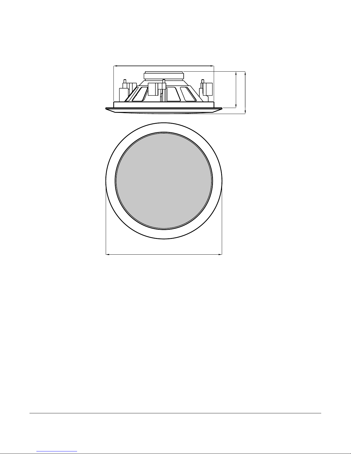
The PL 60 is designed for flush-mount installation
in false ceilings. Before installing the speaker, make
sure that there is sufficient space behind the false
ceiling panel to hold the speaker: with respect to the
support surface of the front flange of the speaker, a
free space of 65 mm (2.56”) depth is necessary.
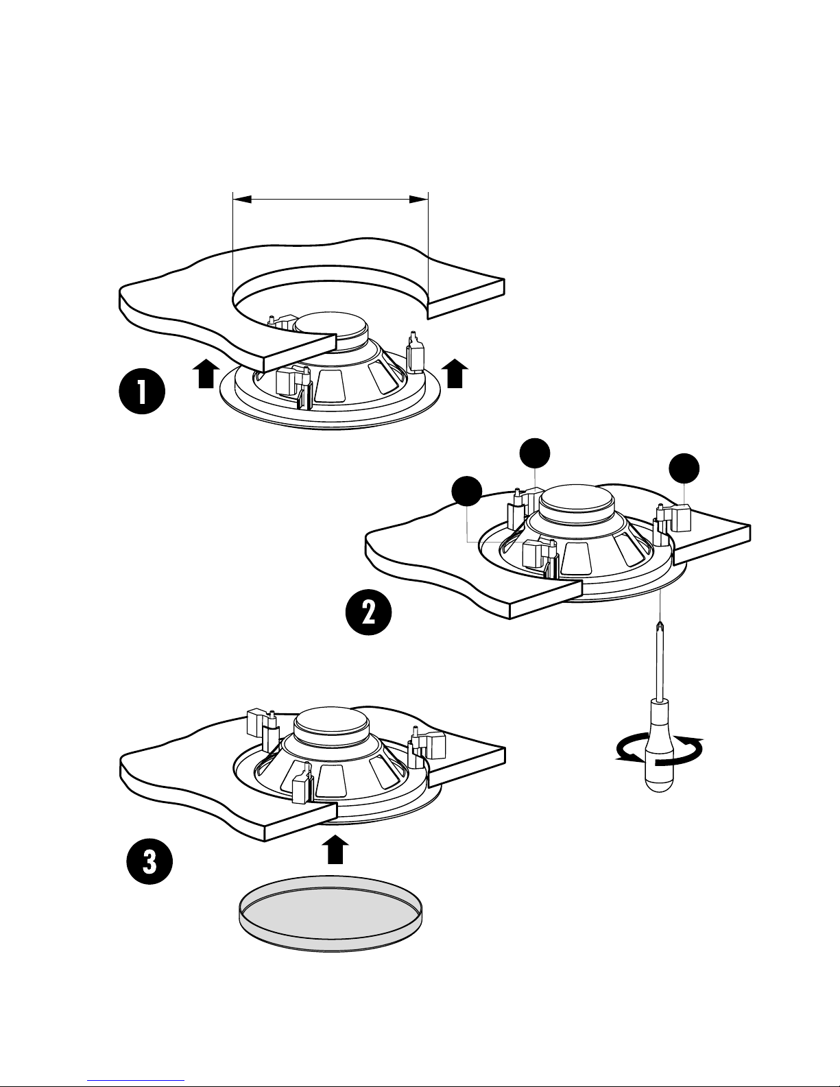
1. Drill a hole of diameter 182 mm (7.16”) in the
false ceiling at the point chosen for installing the
speaker.
2. Insert the speaker in the hole as shown in point 1
of Figure 1 on page 22.
3. Screw in the three screws that tighten the three
attachment terminals Aof the speaker, as shown
in point 2 of Figure 1 on page 22.
4. Fit the metal protective mesh onto the front of the
speaker as shown in point 3 of Figure 1 on page
22.
The A1360 adapter accessory can be requested for
surface mount installation. To view the complete
updated range of accessories available, contact your
nearest sales point.
5. Connection
WARNING: To prevent the risk of electric
shock, do not connect the speaker with
the amplifier switched on.
Before using the speaker, carefully check that all
the connections have been made correctly to make
sure there are no accidental short circuits that could
cause electrical sparks.
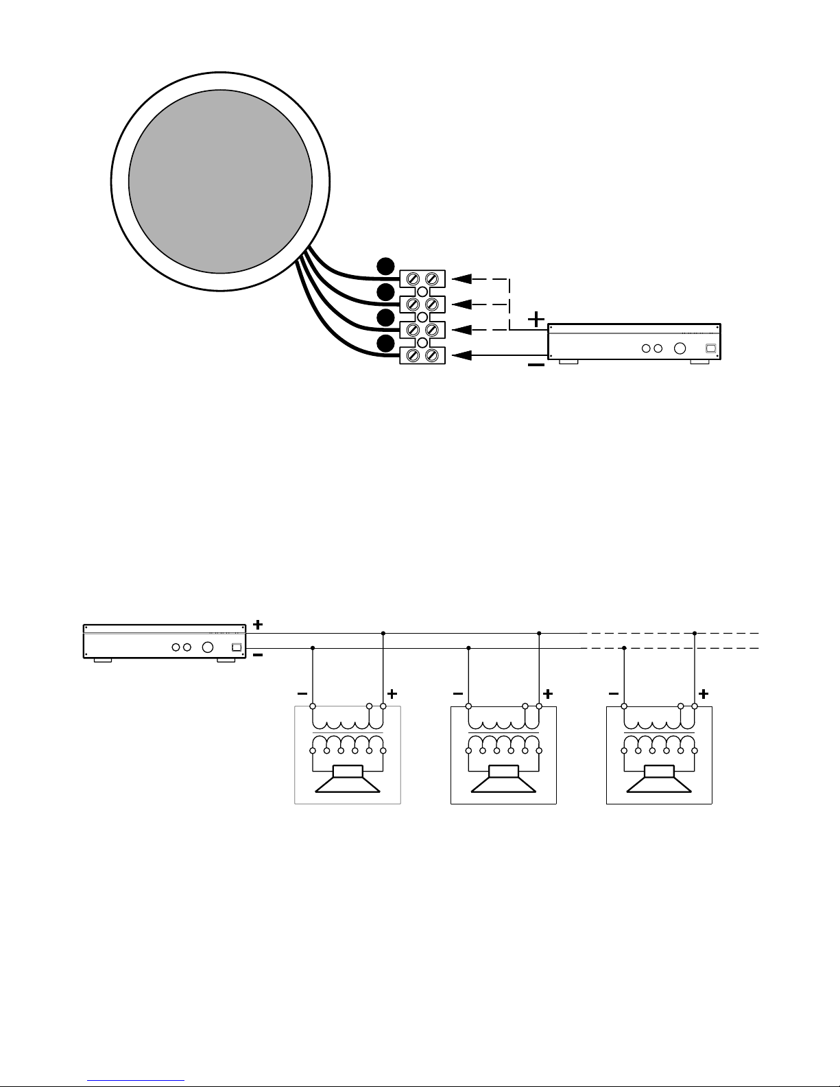
The PL 60 speaker can be connected to constant
voltage audio lines at 70 V or 100 V. Connections are
made using the 5-pin input terminal strip on the rear
part of the speaker.
1. Using the legend in Figure 2 on page 23, locate
the input conductors to be used.
2. Connect the BLACK conductor of the speaker to
the negative conductor (-) of the audio line that
leads from the amplifier terminal marked -, 0, or
COM (Fig. 2).
8
3. Connect the other speaker conductor located
using the legend to the positive conductor (+) of
the audio line (Fig. 2).
VERY IMPORTANT: To prevent speaker
damage, never use the GREEN conductor
when the speaker is supplied with 100 V
lines.
4. To prevent the risk of electric shock, situate the
terminal strip in an inaccessible position (e.g.
inside the speaker when it is used with the acces-
sory for surface mount installation).
When making the connections, keep the following
indications in mind (Fig. 3, page 23).
• The input voltage selected on the speaker must
correspond with the voltage selected on the ampli-
fier.
• The sum of the operating power values of all the
speakers connected to the audio line must not exceed
that of the amplifier.
• To ensure correct audio reproduction, the con-
nections should be made "in phase", where the +/-
polarities of the amplifier output correspond with the
+/- polarities of the speaker input.
A CLOSER LOOK: When two speakers
reproduce the same frequencies but with
phase differences, these frequencies may
be annulled. In sound systems, speakers are often
situated in adjacent positions and the sound waves
produced interact with each other. If a speaker is con-
nected incorrectly; i.e. the polarity of the audio line
conductors is inverted, the audio signals are tran-
smitted with differences in phase and correct repro-
duction is therefore jeopardized.
6. Service
If the product seems to be not operating correctly,
before contacting the service centre, carry out all the
tests the may confirm the malfunction. In many pro-
ducts taken to the service centre, it is not possible to
reproduce the malfunction indicated because the pro-
blem is probably to be found elsewhere in the sound
system. If the product does require service, place it in
its original packaging and take it to your local dealer
or to the nearest service centre.

7. Appendix A- Input cable
For connecting the speaker use cables with an ade-
quate cross-section. The greater the distance
between the amplifier and the speaker, the larger the
connection cable cross-section should be.
To prevent inductive phenomena from giving rise to
humming or disturbance that jeopardize the effective
operation of the audio system, the speaker cables
should not be run together with electrical energy con-
9
ductors, microphone cables, or low level audio lines
(e.g. LINE level).
To facilitate the ‘’in phase’’ connection of the
speaker, use bipolar cables that have markings to
distinguish the polarity (e.g. insulation of different
colours, conductors of different colours, ect.).
To minimize the inductive effects (hum) due to cou-
pling with surrounding electrical fields, use cables
with conductors braided together.
8. Specification
Acou tic y tem
Frequency range (-10 dB):
90 Hz - 20kHz
Frequency response (-3 dB):
110 Hz - 20 kHz
Horinzontal angle of coverage:
90°, average from 800Hz to 16kHz
Vertical angle of coverage:
90°, average from 800Hz to 16kHz
Directivity factor Q (DI):
8 (9), average from 800Hz to 16kHz
Sensitivity1:
91 dB 1W @ 1 m
Calcutated maximum sound pressure (SPL):
106.5 dB @ 1 m (3.3 ft.), maximum power
Impedance:
70 V: 3300Ω- 1.5W; 1660Ω- 3W;
817Ω- 6W
100 V: 3300Ω- 3W; 1660Ω- 6W
Input voltage:
70V, 100 V
Selectable power values:
70V: 1.5 W - 3 W - 6 W
100 V: 3 W - 6 W
Tran ducer
Extended range:
1 dual cone loudspeaker diam. 160 mm (6")
Phy ical characteri tic
Main body:
Plastic material
Grille: Steel
Attachment system:
Flush-mount
Inputs: 5-pin terminal strip
Dimensions (diam. x depth):
Ø 204 x 75 mm (Ø 8.03” x 2.95”)
Weight: 0.8 kg (1.8 lbs.)
Acce ory
A1360 Base for surface mounting
1 Measured on the axis in free field, with input signal of 1 watt (2.83 V RMS @
8ohm) and referring to one metre of distance using the inverse square root
law. The sound pressure indicated represents an average from 300Hz to 3kHz.
Disclaimer
RCF S.p.A. applies a company policy based on constant research and development. With the aim of constantly improving
our products, we reserve the right to make any aesthetic or functional modifications at any time and without prior notice.
RCF is a registered trademark of RCF S.p.A.
Any other trademark mentioned herein is a trademark or registered trademark of the respective owners, who we gratefully
acknowledge. ©2004 RCF S.p.A.. All rights reserved. Printed in Italy.

Fig./Abb. 1
- Installazione a parete •
Wall installation •
Installation au mur •
Wandinstallation •
Instalacion a pared
22
A
A
A
A
182mm (7.16")
9. Figure • Figure • Figure • Abbildunge • Figura

23
A
B
C
D
Amplificatore / Amplifier
Fig./Abb. 2
- Collegamenti •
Connections •
Connexions •
Anschlüsse •
Conexiónes
A =
nero •
black
• noir •
schwarz
• negro (COM)
B =
rosso •
red
• rouge •
rot
• rojo (1,5W/70V - 3W/100V)
C =
giallo •
yellow
• jaune •
gelb
• amarillo (3W/70V - 6W/100V)
D =
verde •
green
• vert •
grün
• verde (6W/70V - N.C./100V)
Pa > Pd x n Va Vd=Va Vd=Va Vd=Va
Pa
= Potenza amplificatore •
Amplifier power
• Puissance amplificateur •
Leistung des Verstärkers
Potencia amplificador.
Pd
= Potenza diffusore •
Speaker power
• Puissance enceinte •
Leistung des Lautsprechers
• Potencia difusor.
n
= Numero diffusori •
Number of speakers
• Nombre d’enceintes •
Anzahl der Lautsprechers
• Numero difusores.
Vd
= Tensione ingresso diffusore •
Speaker input voltage
• Tension entrée enceinte
Eingangsspannung des Lautsprechers
• Tension entrada difusor.
Va
= Tensione uscita amplificatore •
Amplifier output voltage
• Tension sortie amplificateur
Ausgangsspannung des Verstärkers
• Tension salida amplificador.
Fig./Abb. 3
- Collegamento di diffusori con trasformatore in un impianto a tensione costante.
Connecting speakers with transformer in a constant voltage system.
Connexion d’ enceintes avec transformateur dans un système à tension constante.
Anschluss der Lautsprecher mit Transformator an einer Anlage mit konstanter Spannung.
Conexión de difusores con transformador en una instalacion a tension constante.
Amplificatore
Amplifier
• Amplificateur
Verstärker
• Amplificador

MOD. 1876/2
RCF S.p.A.
Sede legale: 42100 Mancasale (RE)-Via Raffaello, 13-Tel. +39 0522 274411 - Fax +39 0522 232428
204mm [8.03"]
178mm [7.01"]
75mm [2.95"]
65mm [2.56"]
Fig./Abb.4 - Dimensioni •
Dimensions
• Dimensions •
Abmessungen
• Dimensiones
Other manuals for PL60
1
Table of contents
Other RCF Speakers manuals