RCS TX-5 User manual

P.O Box 578 Casino, NSW, 2470 Australia
Phone: International ++614 2902 9083
Australia (04) 2902 9083
Website: http://rcs-rc.com
E mail: [email protected]
TX-5
Digital Proportional R/C
TABLE OF CONTENTS
PROVIDED IN INSTRUCTIONS.
Page # 1 Introduction.
Page # 2 Preparing the TX-5. Binding.
Page # 3 Preparing & driving Live Steam locos.
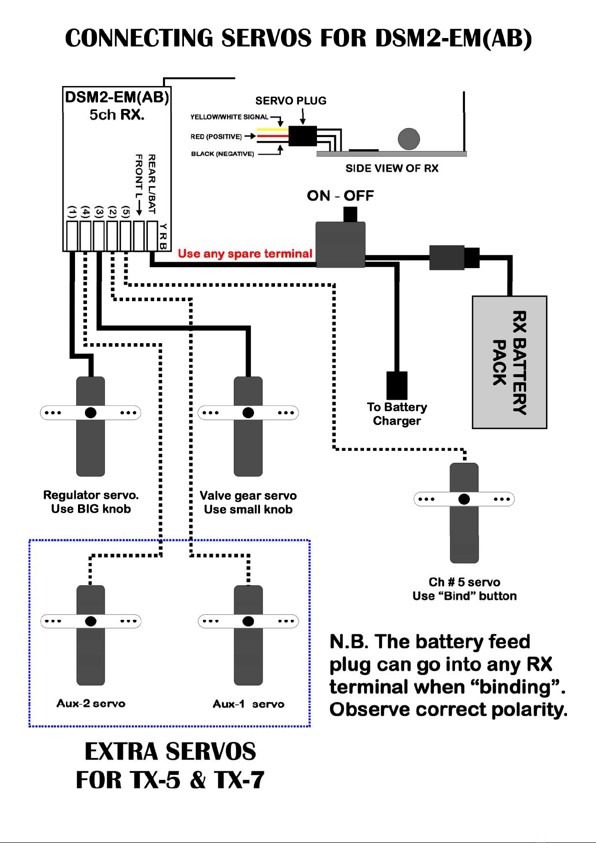
Page # 4 & 5 Diagrams of servo connections.
Page # 6 Using with a Low OFF battery R/C ESC.
Other instructions for use with battery R/C are
found with the ESC.
http://www.rcs-rc.com/pages/instructions
Thank you for purchasing this DSM2 5 channel TX handpiece.
THE PRIMARY PURPOSE OF THE TX-5 IS FOR CONTROLLING LIVE STEAM LOCOS.
THE SECONDARY PURPOSE IS FOR USE WITH CENTRE OFF ESC’s.
WE NOW RECOMMEND USING THE TX-5 WITH RCS ESC’s THAT HAVE AN BV1 OPERATING PROGRAM
INSTRUCTION MANUAL
THESE INSTRUCTIONS REFER SPECIFICALLY TO THE DELTANG R/C BASED TX-5 HANDPIECE.
They should be read in conjunction with the RCS ESC you are using.
SMALL KNOB SETS THE VALVE GEAR.
300º KNOB CONTROL OF REGULATOR.
2 X 300º KNOB CONTROL SERVO FOR
OTHER FUNCTIONS SUCH AS
DRAINCOCKS, BLOWERS ETC.
1 X FULL MOVEMENT SERVO.
REMOVE REAR OF TX-2S TO INSERT
THE 9 VOLT BATTERY.
ALL FOUR KNOBS CAN BE USED FOR
SETTING DIRECTION & SPEED.
1 X FULL MOVEMENT SERVO.
AUX KNOBS CAN BE USED FOR SOUND
SYSTEM TRIGGERS.
PRIMARY USE IS WITH LIVE STEAM LOCOS.
CAN ALSO BE USED WITH MOST RCS “LOW OFF” ESC’s (Not # RBP-RCS)
THE TX-5 IS GUARANTEED FOR ONE YEAR.
When used for battery R/C you will supply a locomotive or trail car, the 14 – 20 volt traction batteries (depending on ESC), a fuse,
ON-OFF switch and wires where necessary, to connect the ESC to the battery and motor(s).
Where soldering is necessary, we recommend a low wattage soldering iron and resin core solder.
TO AVOID CONFUSION WITH OTHER OPERATORS, WE SUGGEST YOU MARK THE TX TO SHOW WHICH LOCO IT IS OPERATING.
CAUTION
DO NOT ATTEMPT TO ALTER THE TUNING OF THE RADIO EQUIPMENT.
DO NOT USE RADIO CONTROL EQUIPMENT IN THUNDERSTORMS.
CHILDREN UNDER 12: ADULT SUPERVISION RECOMMENDED DURING USE.!!
RCS TX & RX PRODUCTS MUST NOT BE USED FOR CONTROLLING RIDE ON LOCOMOTIVES CAPABLE OF
CARRYING MEMBERS OF THE GENERAL PUBLIC.

– 2 –
PREPARING THE #TX-5
THESE INSTRUCTIONS REFER TO THE RCS TX-5 2.4 GHz 5 CHANNEL R/C.
LAYOUT OF THE TX-5 TRANSMITTER HAND PIECE.
Pictures below show the TX-5v1 TX handpiece. The only difference is the case size & text.
The valve gear knob is in the upper middle. The steam regulator knob sits just below.
Top left is the ON – OFF switch. Top right is the Bind/Ch # 5 pushbutton.
The other two knobs can be used for any servo controlled function.
AUX 1 = Ch # 2. AUX 2 = Ch # 4
1. “BINDING”.
The 1st procedure is to “BIND” the receiver (RX) to the Transmitter (TX).
“BINDING” is accomplished by following a few simple steps below.
When binding we recommend removing the servos from the RX.
HOW TO “BIND” USING A DSM2 RX OR RCS Rx65b & ALPHA-3v2 ESC’s.
1.1 LIVE STEAM. Insert the “BINDING” plug supplied with the DSM2 RX into the “BINDING” pins on the RX.
You can also use the # BINDER switch assembly if you do not wish to get inside the loco.
1.1 Rx65b & ALPHA-3v2 ESC’s See 1.2 below. Turn on the loco power >RX and wait 20 seconds for the RX to enter
bind mode. RX LED will flash rapidly OR;
1.1 OTHER ESC’s. See Live Steam above.
1.2 Turn the loco RX ON. The RX LED will start blinking very rapidly to indicate it is ready to be bound.
1.3 Turn on the loco power >RX and wait 20 seconds for the RX to enter bind mode. RX LED will flash rapidly
1.4 Press and hold the right pushbutton on the handpiece marked with a hexagonal symbol. You may need to keep
TX & RX about 1 x metre apart for binding to take place.
1.5 Then press and hold the ON – OFF button to ON. Hold both buttons until the RX LED stops flickering & starts
blinking slowly. Then let both TX buttons go. The TX button also blinks slowly & then goes to solid ON.
1.5 The LED on the RX will blink more slowly and then go solid ON.
1.5 The LED on the DELTANG ESC will behave the same.
1.6 When “BINDING” is complete the RX LED will change to solid ON.
N.B. “BINDING” plug MUST be removed BEFORE the SYSTEM is turned OFF. (#BASIC-3 has no binding plug)
1.7 The “BINDING” plug is removed & stored safely.
RCS offers an optional extra # BINDER cable and switch. When fitted this will enable any non RCS loco to be bound to
any TX without requiring access to the inside of the loco. This will enable any loco to be swapped between any other
DSM2 TX’s. You will be able to “hand off” speed matched locos for MU’ing into a consist. (Uneeded with #BASIC-3)

- 3 -
2. PREPARING FOR USE WITH LIVE STEAM LOCOS.
(N.B. there is no centre détente on the big throttle knob).
Make sure the RX is OFF. Then re-insert the servos into the correct RX sockets.
The regulator servo goes in Ch # 1 (Throttle) socket.
The valve gear servo goes in Ch # 3 (Elevator) socket.
When using for the first time make sure both knobs are centered. Turn ON the TX-5 handpiece.
VALVE GEAR SERVO
1.1 Then turn on the Live Steam loco RX. The two servos should immediately snap to the neutral position.
1.2 Adjust the valve gear servo connecting rod to ensure the centre position of the valve gear matches the servo.
1.3 Turn the small knob slowly to the right Clockwise (CW) and check that the servo moves the valve gear to the
forward position.
If it goes the wrong way you will need to reverse the mechanical connection.
If the small knob wants to make the servo move too far put the connecting rod into a servo arm hole closer to the
middle of the servo arm. If it does not move far enough move the rod into a hole further out.
N.B DO NOT FORCE THE SERVO AGAINST THE STOP. DOING SO WILL DAMAGE THE SERVO.
1.4 Turn the small knob slowly and carefully to the left Counter Clockwise (CCW). With regards to any possible
mechanical changes you made during 1.3 above, it should perform correctly.
STEAM REGULATOR SERVO
2.1 Turn the large knob to the left (CCW) the servo will rotate CCW and should close the steam regulator valve.
If it goes the wrong way you will need to reverse the mechanical connection.
If the large knob wants to make the servo move too far, i.e. over shutting the regulator, put the connecting rod into a
servo arm hole closer to the middle of the servo arm. If it does not move far enough move the rod to a hole further out.
N.B DO NOT FORCE THE SERVO AGAINST THE STOP. DOING SO WILL DAMAGE THE SERVO.
2.2 Turn the large knob to the right to check the servo opens the steam regulator far enough.
IF MECHANICALLY CHANGING THE SERVO CONNECTIONS IS NOT POSSIBLE, THERE IS A SUITABLE LOW
COST IN LINE SERO REVERSING MODULE AVAILABLE FROM RCS.
Make sure the TX is OFF and both knobs are in the middle. This is the same as the throttle & elevator sticks on a
conventional stick R/C being centered. . You can feel the détente when twisting the small knob.
Turn TX-5 hand piece ON before the loco. When the loco is linked turn the big knob fully to the left (CCW).
Once steam has been raised select the direction of valve gear with the small knob.
Then turn the big knob CW. That is like raising the throttle stick on a conventional stick R/C.
Turn the big knob CCW to slow the loco. All the way CCW will bring the loco to a stop.
You can have a faster stop by centering the valve gear control knob. Then make sure the big knob is also fully CCW.
The Bind button doubles as a whistle control with a servo on Ch # 5. It starts off at one extreme and when pressed goes
fully the other way. It snaps back to the start point when released.
Two AUX knobs can be used to control full servo movement functions. Or perhaps triggering a sound system.
It is possible to have directional head & tail lights with the addition of a # 2-M-F connected in parallel with the valve gear
servo on Ch # 3. How to wire that feature is shown in the # 2-M-F instructions.
Turn OFF the loco BEFORE the TX-5 handpiece.
TURNING TX-5 ON. SETTING THE VALVE GEAR FOR
FORWARDS.
SETTING THE VALVE GEAR FOR
REVERSE.


- 6 -
4. USING THE TX-5 WITH AN RCS “LOW OFF” ESC’.
The TX-5 can be used with RCS LOW OFF ESC’s such as the Rx65b, ALPHA-3v2 & OMEGA-3v6k.
This TX-5 hand piece is essentially a 5 channel stick R/C in a smaller case.
Make sure the large throttle knob is fully CCW (OFF) and small knob is centered before you switch the system on.
Switch on the TX-5 first & then the ESC. (Unless binding)
1. The large knob controls channel # 1, the throttle. Make sure the knob is fully CCW before switching on. This is the
same as the Channel # 1 stick being fully down.
2. The small knob is the same as a Ch # 3 elevator stick.
Turning the small knob to the right (CW) is the same as pushing the elevator stick forwards.
Turning the small knob to the left (CCW) is the same as pulling the elevator stick backwards.
3. From neutral, set the small knob to the direction you want and leave it there. CW for forwards.
4. Twist the large throttle knob to the right (CW) to accelerate.
5. To slow down twist the large knob to the left (CCW) until desired speed is reached.
6. To stop loco turn the large knob fully to the left (CCW).
Throttle must be at OFF before changing direction. Pause at neutral for one second when changing direction.
7. To select reverse direction turn the small knob to the left (CCW) and leave it there.
To speed up, slow down & stop in reverse, repeat steps 4, 5, 6, & 7.
All RCS ESC’s have directional lights and at least one sound trigger.
With Rx65b & ALPHA-3v2 the Ch # 5 button can also be used as a sound trigger. Not with # OMEGA-3v6.
The two AUX knobs can be used as 4 x sound triggers F1, F2, F3 & F4 on an # OMEGA-3v6k.
If the directional lights are incorrect, swap over the wiring to them so they match the loco speed and direction.
#ALPHA-3 ESC’s have directional lights and two sound triggers.
If your ESC does not have directional lights, the # DSM2-EM(AB) RX has directional LED lighting outputs. OR:
RCS has a small add on module # 2-M-F that reads the speed and direction of the Channel # 3 output and switches
lights accordingly. A standard servo “Y” cable is needed. Not supplied.
The other functions are likely the same as they are for RCS if your centre off ESC has them fitted.
If there are no sound triggers you can add another # 2-M-F to channel # 2 for two sound triggers.
Add another # 2-M-F to channel # 4 for two more sound triggers.
SEE THE SEPARATE ESC DIAGRAM INSTRUCTIONS FOR HOW TO WIRE A PARTICULAR BRAND.
Table of contents
Other RCS Remote Control manuals


