7
RCT. Simplify monitoring.
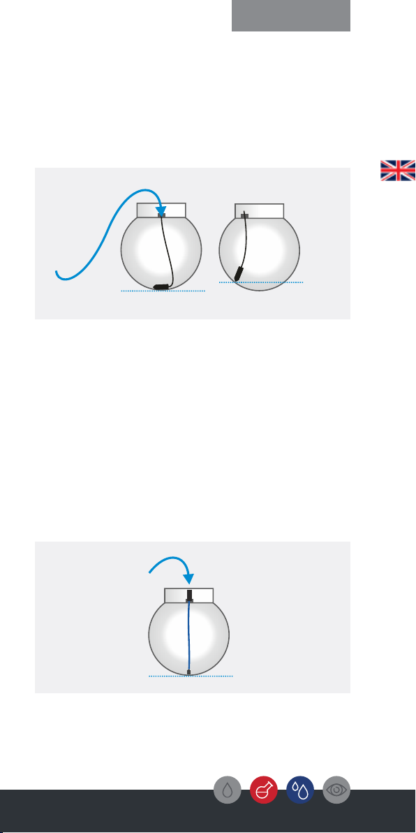
Fig. 2 | Pressure probe with screw plug
Fig. 3 | Capacitive sensor
Step 1: Zero adjustment
For the pressure probe:
(Fig . 2)
(Fig. 1, Page 5)
Completing the zero adjustment
For the capacitive sensor:
(Fig. 3)
(Fig. 1, Page 5)
Operation
Carefully cut the white transportation straps that
hold the pressure probe together. For proper
installation, the probe must be free of twists.
Therefore, leave the probe hanging to straighten
the cable. This may take some time depending on
the temperature.
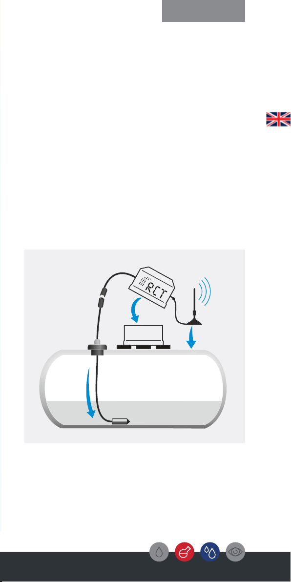
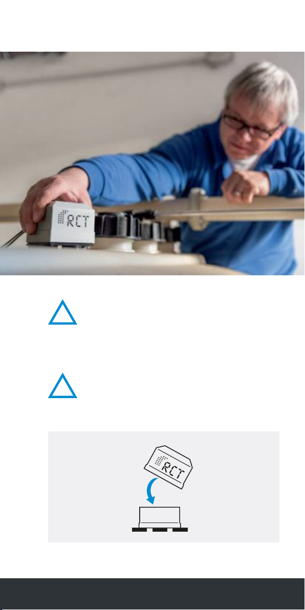
Mount the antenna of the transmitter and place it
on a metal surface with the magnet. Connect the
pressure probe to the transmitter via the screw
connector and activate the device by plugging in
the battery. Remove the black safety
sticker placed over the contact before plugging it
together.
Mount the antenna of the transmitter and place it
on a metal surface with the magnet. Connect the
capacitive sensor to the transmitter via the plug
connection and activate the device by plugging in
the battery.
Remove the black safety sticker placed over the c
ontact before plugging it together.Make sure that the
sensor does not come into contact with conductive
materials during the measurement time. When the
red and green LEDs light up, the measuring process
is finished. The capacitive sensor can be placed on
the floor.
Then wait about one minute until the device has
sent the data. You can optionally see this in the
Mobile App "RCT Monitor" (see step 6).
The transmitter unit has now transmitted an AD
value to the server, which represents an empty
tank - on the condition that the probe did not come
into contact with other media or liquids during the
measurement. Via the Mobile App or Web App you
can see this transmitted AD value, which is usually
between 10 and 200. Please now assign this value
via the App or Web App as 0%, 0 cm, or 0 liters
(depending on the desired physical unit of size).
This completes the zero adjustment.
Then disconnect the device from the battery again
and go to step 2.