RD DS6600-15M User manual

OPERATING MANUAL
JDS6600 Series
Digital Control Dual-channel
DDS Signal Generator
Rev1.0
MAY 2017

2
Contents
1.Inspecting Package Contents....................................................................1
2.Summary...................................................................................................2
2.1 Brief Introduction..........................................................................................................2
2.2 Model Introduction....................................................................................................... 2
2.3 Dimention......................................................................................................................2
2.4 Technical parameters.....................................................................................................3
3.Instrument Introduction............................................................................6
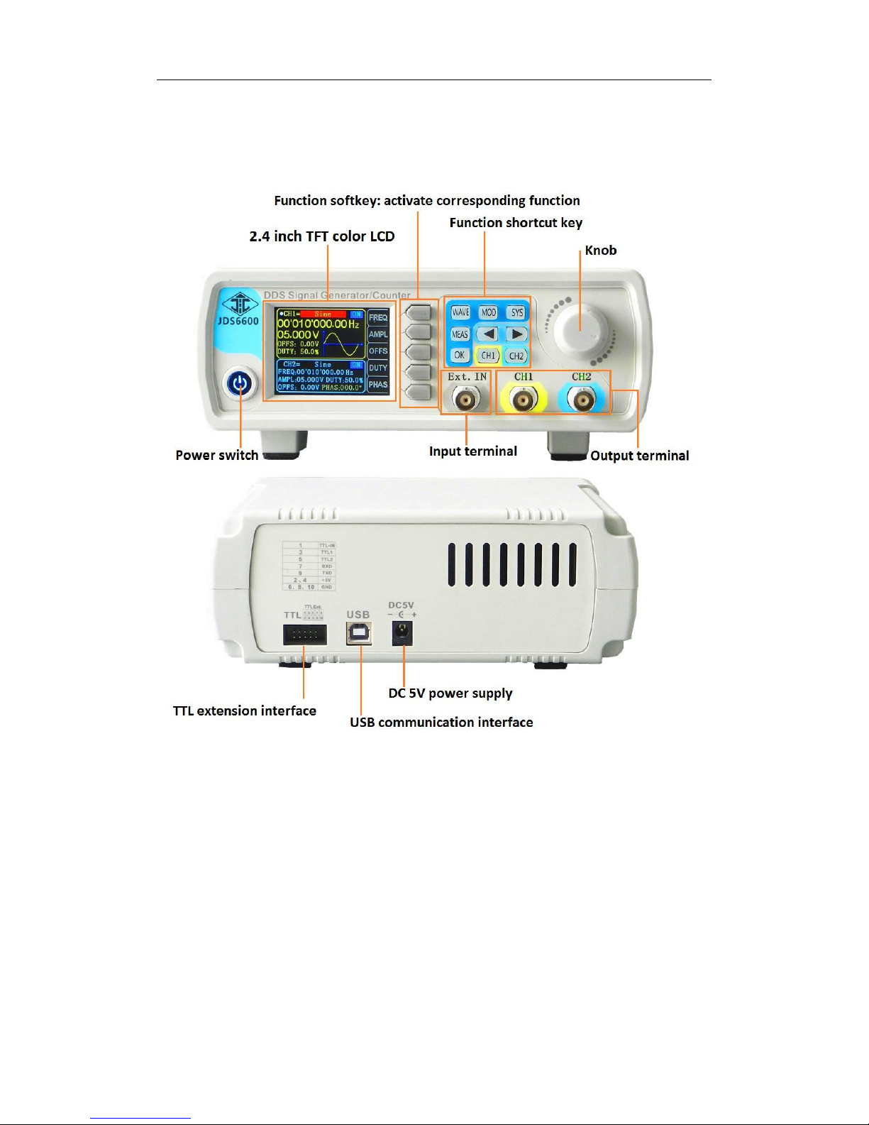
3.1 Front Panel Introduction............................................................................................... 6
3.2 Rear Panel Introduction................................................................................................ 6
3.3 Display Interface Introduction......................................................................................7
3.4 Button fuction Introduction.......................................................................................... 7
4.Operation Introduction............................................................................. 8
4.1 Introduction of Main Interface......................................................................................8
4.2 Introduction of Measurement Mode Interface..............................................................8
4.3 Introduction ofModulation Mode Interface..................................................................8
4.4 Introduction ofSystem Setting Interface.......................................................................9

1
1.Inspecting Package Contents
When you get a new JDS6600 series dual channel DDS signal generator, please inspect device as follows:
1.1 Inspect the shipping container for damage.
If there are damages in the container or foam, keep them until the whole machine and the accessories passing
the electrical and mechanical tests. If your instrument has damaged during shipping, please contact your seller and
us for compensation.
1.2 Check the Accessories
All contents are as follows, if there is missing, damage or wrong, please contact us or reseller.
Host:JDS6600
1pcs
Accessories:DC adapter
1pcs
USB cable
1pcs
Signal output cable
2pcs
User manual (PDF)
1pcs
CD
1pcs
1.3 Check the instrument
In case of any mechanical damage or defect, or if the instrument does not operate properly or pass the electrical
and mechanical tests, you can contact us or reseller.

2
2. Summary
2.1 Brief Introduction
JDS6600 series DDS signal generator can generate sine wave, square wave, triangle wave, pulse wave, and
arbitrary wave etc. The frequence will be upto 60MHz. And it has duty-cycle correction, amplitude modulation
function and frequency sweep function, etc. It can show output signal, amplitude and frequency in the same time.
This series has amplitude frequency characteristics, and the appearance is very delicate and beautiful. It can be
applied in factories, schools, research institutes and laboratories.
2.2、Model Introduction
There are 5 models, JDS6600-60M,JDS6600-50M,MJDS6600-40M, JDS6600-30M and JDS6600-15M. The
main difference is the max output frequency of sin wave, as follows:
Model
The max output frequency of sin wave
JDS6600-60M
60MHz
JDS6600-50M
50MHz
JDS6600-40M
40MHz
JDS6600-30M
30MHz
JDS6600-15M
15MHz
2.3
Note :Unit mm

3
2.4 Technical parameters
Frequency Characteristics
JDS6600-15M
JDS6600-30M
JDS6600-40M
JDS6600-50M
JDS6600-60M
Sine frequency range
0~15MHz
0~30MHz
0~40MHz
0~50MHz
0~60MHz
Square frequency range
0~15MHz
0~15MHz
0~15MHz
0~15MHz
0~15MHz
Triangle frequency range
Pulse frequency range
0~6MHz
0~6MHz
0~6MHz
0~6MHz
0~6MHz
CMOS/TTL digital frequency range
Arbitrary wave frequency range
Square rise time
≤25nS
≤20nS
≤15nS
≤15nS
≤15nS
Pulse width adjustment range
150nS-4000S
60nS-4000S
40nS-4000S
30nS-4000S
30nS-4000S
Mininum Frequency resolution
0.01µHz(0.00000001Hz)
Frequency accuracy
±20ppm
Frequency stability
±1ppm/3h
Waveform Characteristics
Waveform
Sine, Square, Triangle, Pulse (duty-cycle correction,Pulse width and cycle time
adjustable),Partia Sine, CMOS, DC level, Half-wave, Full-Wave, Pos-Ladder,
Neg-Ladder, Noise, Exponential Rise, Exponential Fall, Tone, Sinc Pulse, Lorentz
Pulse, and 60 kinds user defined waveform.
Waveform length
2048 points
Waveform sampling rate
266MSa/s
Waveform vertical resolution
14bits
Sine
Harmonic suppression
≥45dBc(<1MHz);
≥40dBc(1MHz~20MHz)
Total harmonic distortion
<0.8%(20Hz~20kHz,0dBm)
Square and Pulse
Overshoot (Square)
≤5%
Duty-cycle range(Pulse)
0.1%~99.9%

4
Ramp wave
Linearity
≥98%(0.01Hz~10kHz)
Output Characteristics
Amplitude range
Frequency≤10MHz
10MHz≤Frequency≤30MHz
30MHz≤Frequency
2mVpp~20Vpp
2mVpp~10Vpp
2mVpp~5Vpp
Amplitude resolution
1mV
Amplitude stability
±0.5%/5 h
Amplitude flatness
±5%(<10MHz); ±10%(>10MHz)
Waveform Output
Output impedance
50Ω±10%(typical)
Protection
All the signal output termianl can be shorted within 60s
DC Offset
Offset adjusting range
Output
Amplitude >4V
0.4V<Output Amplitude≤4V
0<Output Amplitude≤0.4V
-9.99V~9.99V
-2.5V~2.5V
-0.25V~0.25V
Offset resolution
0.01 V
Phase characteristics
Phase adjusting range
0~359.9°
Phase resolution
0.1°
TTL/COMS Output
Low level
<0.3V
High level
1V~10V
Level rise/fall time
≤20ns
External Measurement Function
Frequency meter function
Frequency measurement
range
1Hz~100MHz
Measurement accuracy
Gate time continuously adjusted between0.01s~10s
Counter function
Counting region
0-4294967295
Coupled mode
2kinds Coupling modes, DC and AC
Control mode
Manual operation
Input signal voltage range
2Vpp~20Vpp
Pulse width measurement
0.01us (resolution), 20s (MAX measuring time)
Period measurement
0.01us (resolution), 20s (MAX measuring time)
Sweep Function

5
Sweep channel
CH1 or CH2
Sweep type
linear sweep、log sweep
Sweep time
0.1s~999.9s
Setting range
User settings
Sweep direction
Forward, Backward and Roundtrip
Burst function
Number of pulses
1-1048575
Burst mode
Manual Trig、CH2 Trig、Ext.Tring(AC) 、Ext.Tring(DC)
General technical parameters
Display
Display type
2.4 inch TFT color LCD
Storage and loading
Quantity
100 groups
Location
00 to 99(Power on will load the position 00)
Arbitrary wave
quantity
1 to 60, totally 60 groups(default set 15 groups)
Interface
Interface mode
USB to serial interface
Extension
interface -
There is serial interface of TTL level mode to be
convenient for user development.
Communication
speed
115200bps
communication
protocol
Command-line mode, Open protocol
Power supply
Voltage range
DC5V±0.5V
Manufacturing process
Surface-mount technology, FPGA design, high reliability, long service life
Buzzer
User can set ON or OFF by procedure
Operating characteristics
Full button operation, knob continuous adjustment
Environmental conditions
Temperature:0~40 oCHumidity:<80%

6
3. Instrument Introduction
3.1 Front Panel Introduction

7
3.2Display Interface Introduction
11-CH1 Parameters 12- CH2 Parameters
13-Wave Display 14-Current Channel Output State
15-Function list ofSoftkey 16-Phase angle between CH1 and CH2
3.3 Button function Introduction
name
Introduction
Function softkey
Function softkey can activate the corresponding function on the screen
Enter main interface, or set waveform of currentchannel
Fast switch between measurement mode interface and main interface
Fast switch betweenmodulation mode interface and main interface
Fast switch between system setting interface and main interface
In main interface, press it to control output of CH1 and CH2 in the same time; in
modulation mode interface, press it to control ON/OFF
When setting parameter,press it to move cursor to set step value.
Press it to enter CH1 channel, and press it again to control output of CH1, You can keep
pressing for more than 1sto set CH1 into theprimary channel.
Press it to enter CH2 channel, and press it again to control output of CH2, you can keep
pressing for more than 1s to set CH2 into the primary channel.

8
4. Operation Introduction
Press the power button, the instrument starts and enters welcome interface, and then enters language selection
interface. Press corresponding softkey to choose language, and then enter the main interface lastly. When you
start the instrument in the future, there is no language selection interface, entering the main interfac directly.
4.1 Introduction of Main Interface
4.1.1 Press to open or close the outputof both channels in the same time.
4.1.2 Select channel:Press or to select current channel.Press again to control the channel ON/OFF.
Keep pressing or keyfor more than 1 secondto set the current channel as the primary channel.
4.1.3 Set waveform:Press key toset waveform of current channel; rotate knob to set waveform quickly.
press to switch between arbitrary waveforms and presetwaveforms.
4.1.4 Set frequency: press [FREQ] softkey to enter frequency setting, and press to move cursor to set
the step value. And then rotate the knob to adjust value; keep pressing [FREQ] softkey for more than 1 second to
change frequency unit.
4.1.5 Other parameters setting aresame as 4.1.14 (Keep pressing [OFFS], [DUTY] and [PHAS] to Initialize to
default values)
4.2 Introduction of measurement mode interface
4.2.1 On measurement mode, press [FUNC] softkey to enter the state of switching between measure and counter.
4.2.2 Coupling set:press [COUP]softkey can set the coupling mode to AC and DC.
4.2.3 Set gate time:press [GATE] to set gate time. and press can set step value. And then rotate knob
to adjust value. [MODE] setting is as above. name
4.2.4The operation at counter function are almost same to the operation of measure function.
4.3 Introduction of modulation mode interface
4.3.1 On modulation mode interface, press [FUNC] softkey to enter the state of switching between sweep
frequency (CH1 and CH2)and burst function.
4.3.2 On sweep frequency function (CH1), press move cursor to choose editeditem, after the item
selected, you can press ( or press CHG softkey )and rotate knob to adjust value.
4.3.3 After set all items, press ON softkey to start sweep frequency function, and press OFF to stop.
4.3.4 Other function operation are almost same as above.
Welcome Interface
Language Selection Interface

9
4.4Introduction ofsystem setting interface
4.4.1 Recall and store:it can recall and store current waveform parameter to the specific place, rotate knob to the
specific place. When you want to recall, store and delate, press corresponding softkey.
4.4.2 Sync: When sync, CH1 is the object of operation. CH2 parameter will be changed with the changes of CH1
parameter. When the sync item is selected, you can press or knob to select the sync item needed, press
ON softkey to select and press OFF softkey to cancel.
4.4.3 Other function on system setting interface and other interface operation are similar as above.
This manual suits for next models
4
Table of contents