Kuzma 4Point11 User manual

1
KUZMA 4POINT TONEARM
Instruction manual Serial Number: …..
2020-04

2
KUZMA LTD
INSTRUCTION MANUAL FOR 4POINT tonearm
The 4POINT tonearm is a very precisely engineered piece o equipement, however, the
construction is robust and requires minimal maintenance or optimal per ormance.
Fig.1
CONTENTS Page
General description 3
Product registration and warranty extension 3
Technical data 4
Unpacking and Basic Setup 5-6
Setting up the tonearm 7-9
Adjustment of tracking force 9
Adjustment of tangential geometry 9
Adjustment of VTA 10
Adjustment of azimuth 10
Adjustment of bias 11
Damping 11-12
Adjustment of cueing device 13
Maintenance 13
Transport 13
Troubleshooting 14
Technical appendixes-set up cartridge 15-19
Protractors 20
headshell lock vertical paddle vert. paddle lock horizontal bearing assembly VTA tower
VTA lock
Wire loop
pin or cable
cable - play position
counterweight tracking orce
main counterweights horizontal trough lock trough–horizontal
horizontal paddle
main tube assembly
trough - vertical
ine VTA indicator

3
General description
This di ers rom other arms by incorporating several unique eatures. The zero play bearing
is con igured on 4 points. There is very precise VTA adjustment and, despite a longer
e ective length o 280 mm (11 inches), its the standard mounting distance o 212mm ( or 9
inches arms).
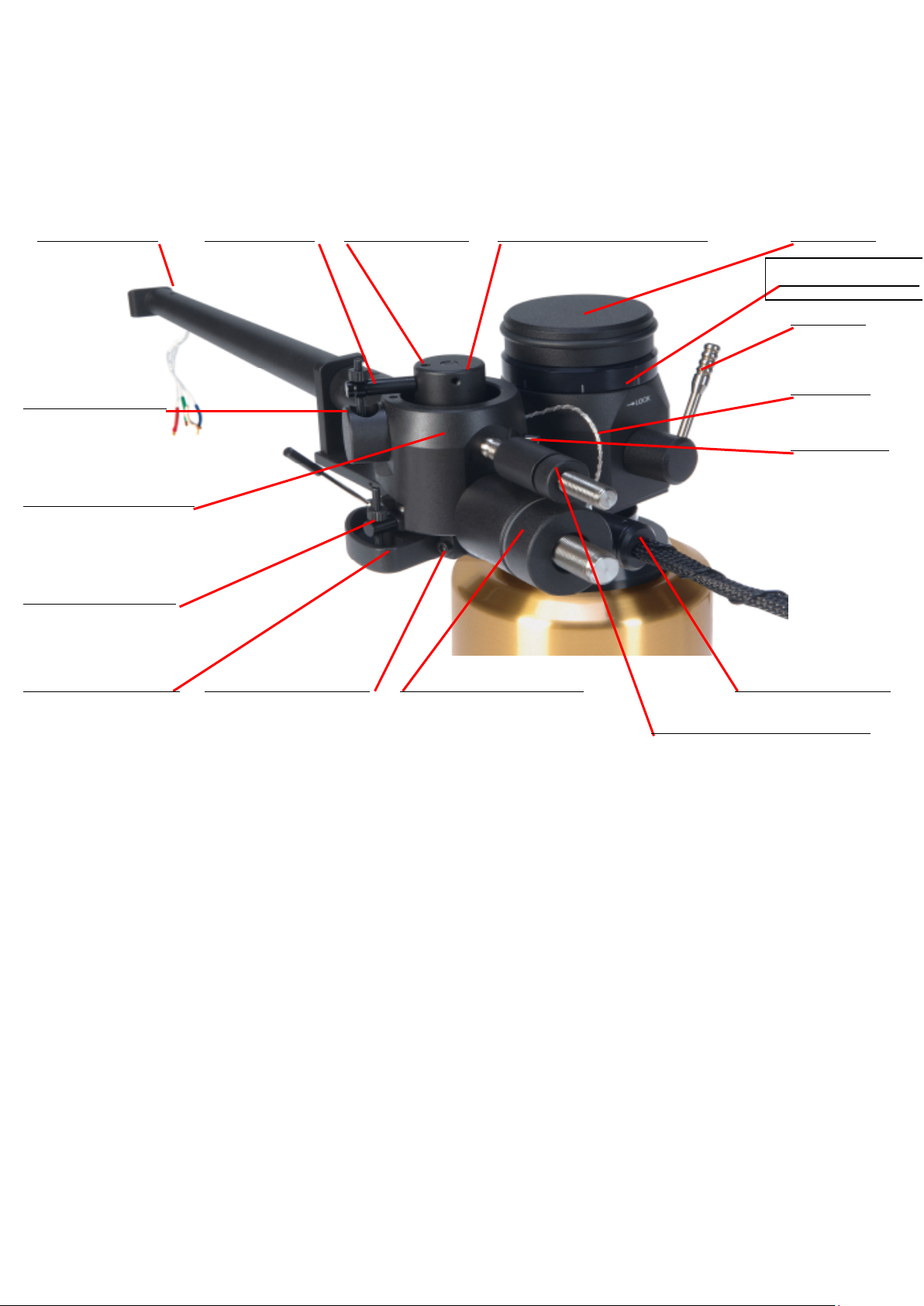
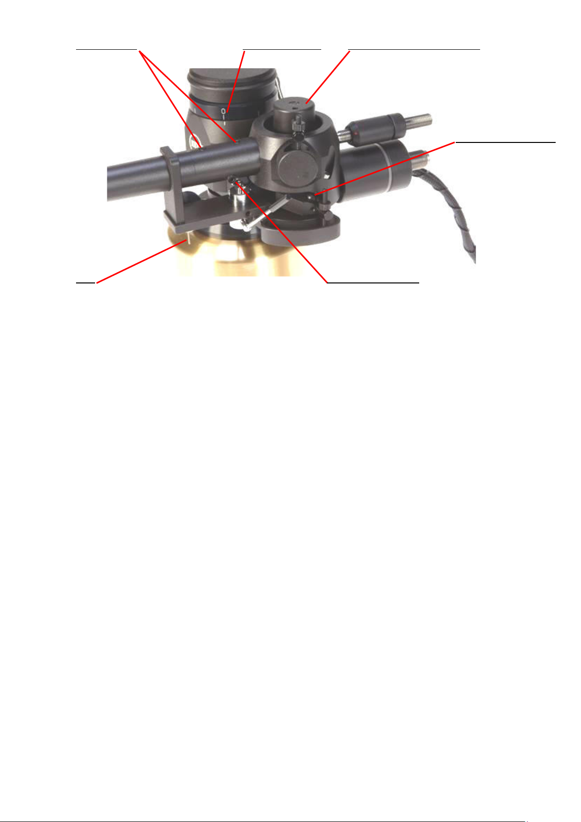
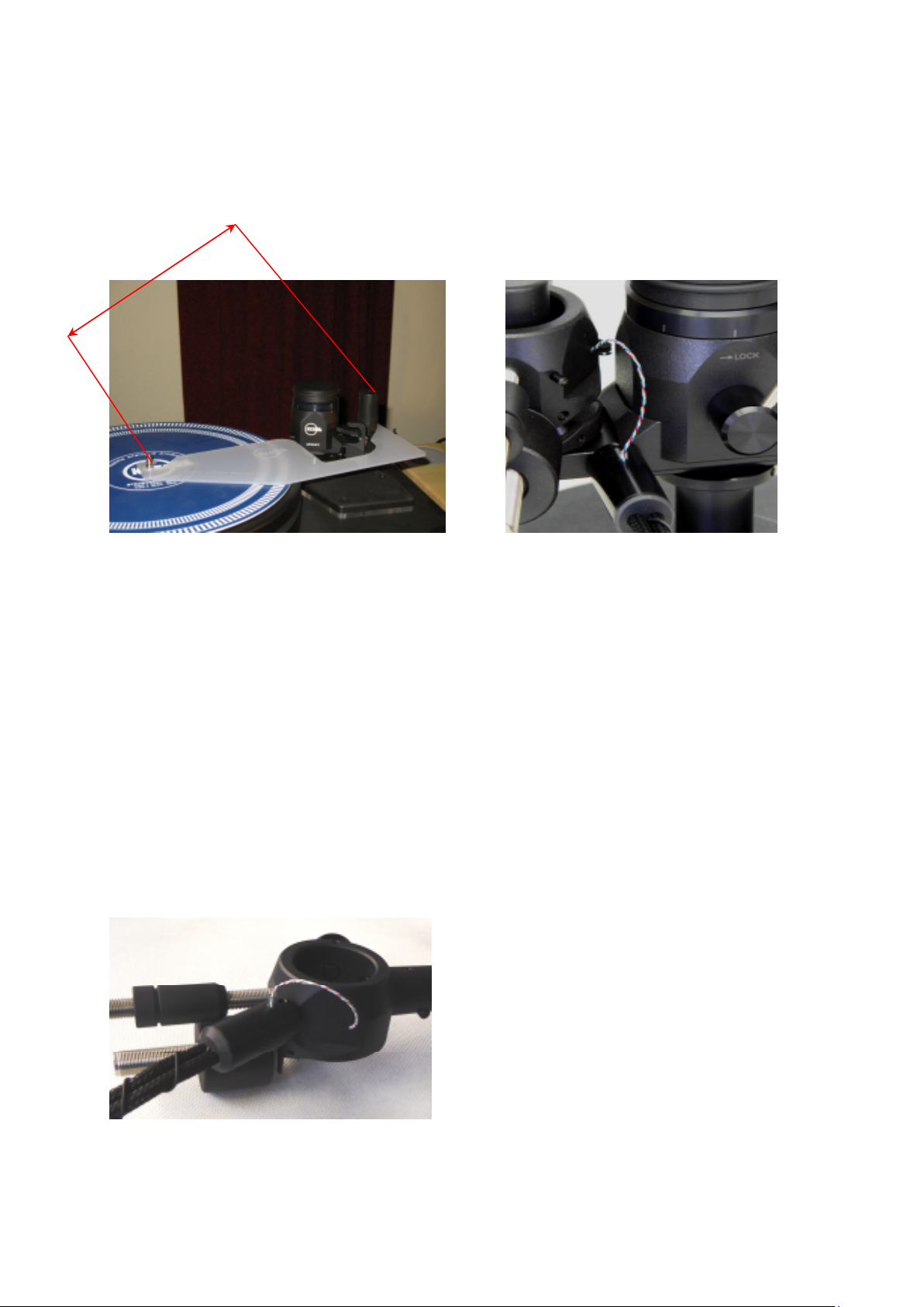
The heart o the new construction is a unique 4 point bearing. The irst set o two points
(similar to a double unipivot bearing) allows vertical movement. The second set o two points
allows horizontal movement. All our points have minimal riction and zero play in all
playing directions thus ensuring the cartridge plat orm and the cartridge itsel move with very
low riction and minimal vibration across the record. It is normal to eel slack in the bearings
in certain directions.
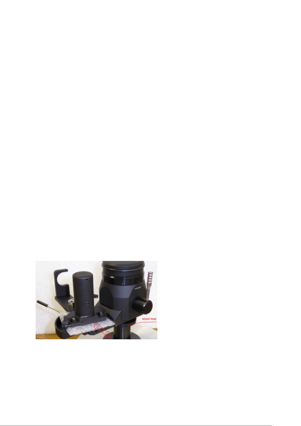
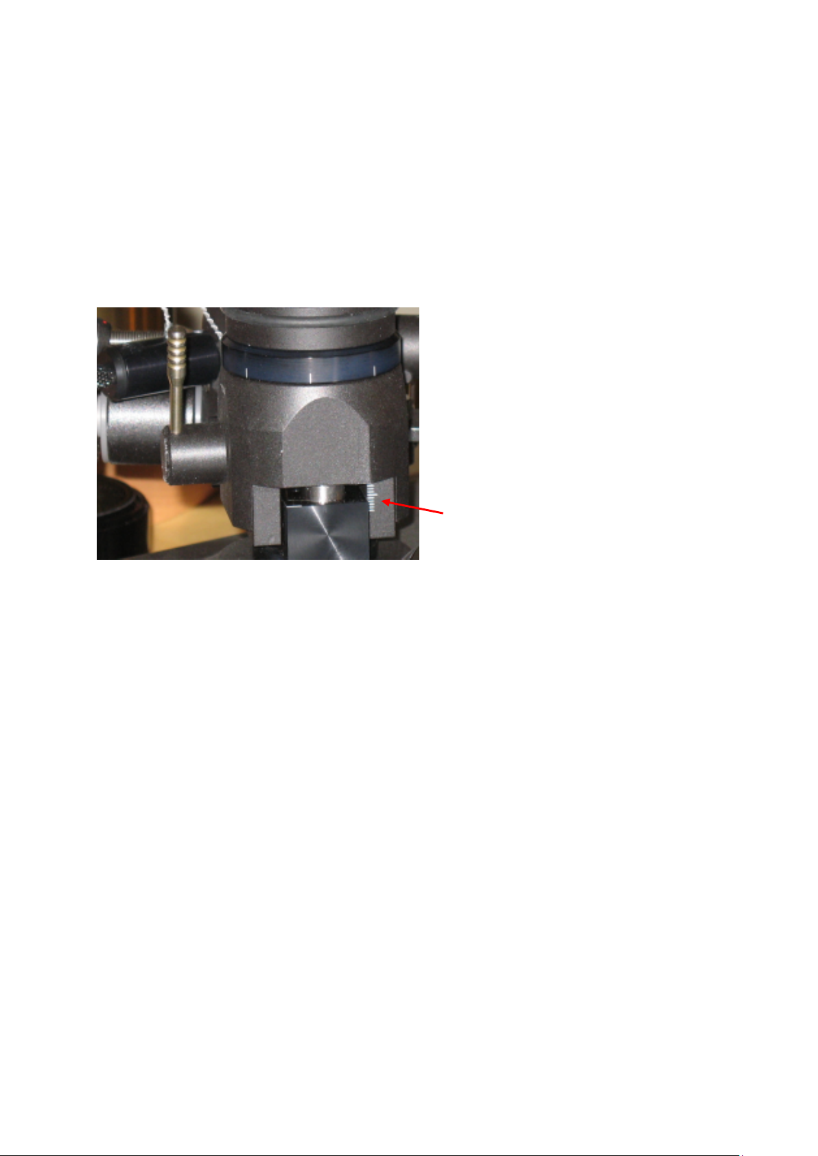
The whole construction is mounted on a rigid VTA tower which allows very precise VTA
adjustment while playing, without any loss o rigidity, yet with up to 0.01 mm o precision
and zero play.
The main tube is constructed and machined rom solid aluminium, similar to our tangential
Air line arm. The main counterweight balances the tonearm and there is a second small
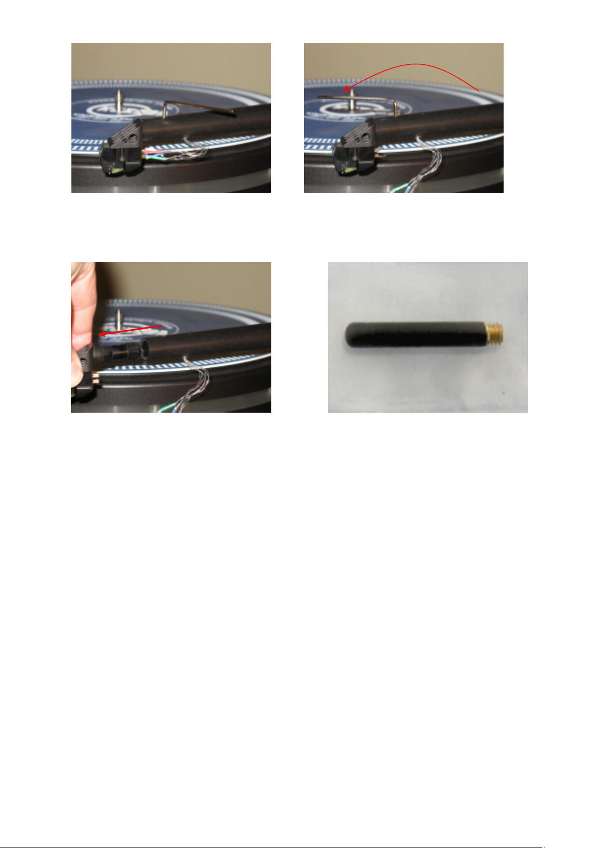
counterweight with which the tracking orce can be inely adjusted. Azimuth can be adjusted
in small repeatable increments with zero play, by means o an Allen key.
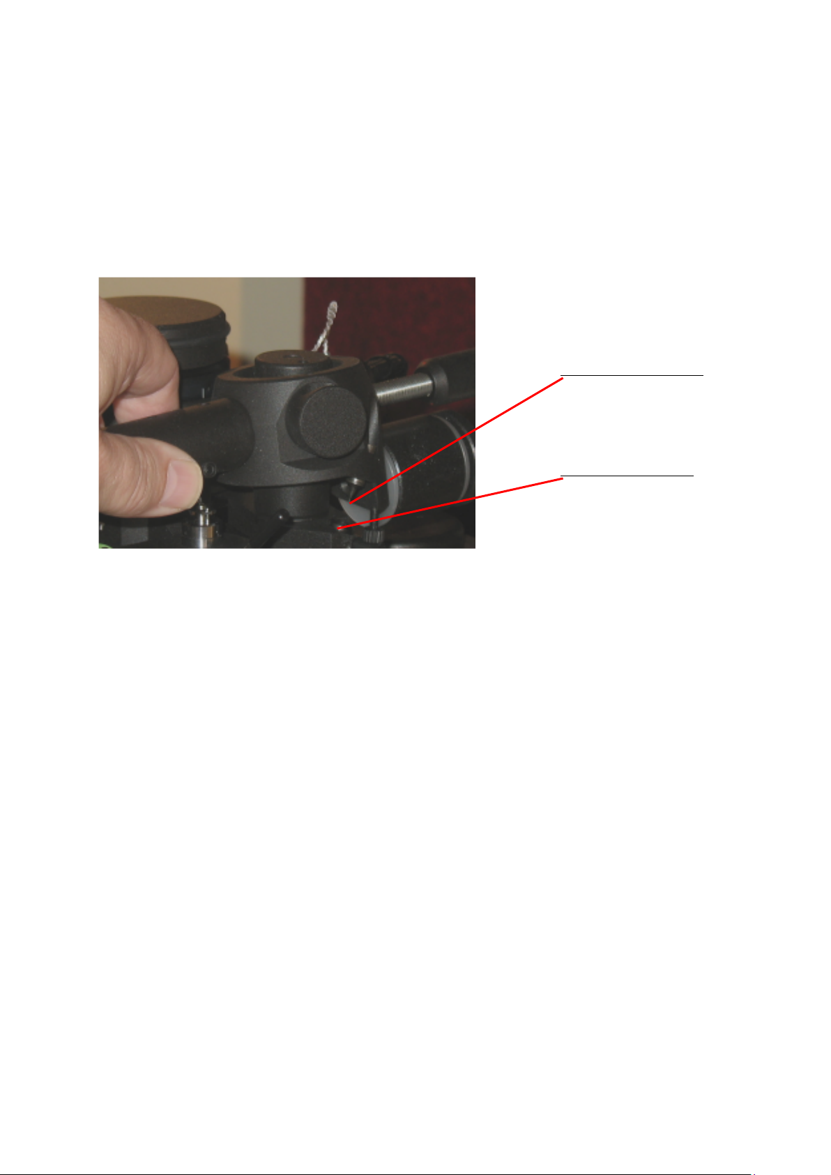
A eature o the tonearm is a unique detachable headshell( one spare included as standard).
The electrical connection is via standard pins but the headshell can be simply removed by
unscrewing with an Allen key. The headshell is ixed with a precise hexagonal locking
system giving the same rigidity as with a ixed headshell.
Two separate troughs damp vertical and horizontal resonances and can be inely adjusted
independently. The troughs can be removed rom the tonearm.
Internal wiring is o superior special alloy silver wires. One set o 4 wires runs unbroken
rom the cartridge pins to the RCA plugs.
Product registration and warranty extension
Kuzma products have a non trans erable 2 year limited warranty on parts and labour, which
may vary in each country.
To obtain the 5 years* limited warranty rom us, you need to register the product on our web
site within 30 days o purchase. We suggest registration o products in any case because this
will also help you to receive our technical support more easily and with resale o products.
Simply register on our web site, complete the orms and you will receive an extended ive
year warranty card on your email within a ew days. * not valid or ex demo products.

4
Fig. 2
Technical data
Mass: 1650 gr
E ective length : 280 mm ( 11 inch)
Mounting distance: 212 mm
O set angle: 19.50 degrees
Distance rom spindle to
horizontal bearing: 264 mm
E ective mass: 18 g
VTA adjustment: yes
Azimuth adjustment: yes
Bias adjustment: yes
Vertical damping: yes
Horizontal damping: yes
Detachable headshell: yes ( one extra supplied)
Cables: silver
Arm mount: Kuzma 212 mm
Optional: biwiring wiring, extra headshells
azimuth lock VTA scale - ine horizontal bearing assembly
vertical bearing point
azimuth adjustment bias

5
1. Unpacking
Open the box care ully and remove top covers.
The tube with vertical bearing points is packed separately (tube assembly) on the top o the
box. Please do handle with care and when put aside, ensure that nothing is touching the
bearing points. Bear in mind how you will handle the termination box and output cable.
The horizontal bearing assembly is permanently mounted on the main VTA arm tower. This
is blocked during transport. (Fig.2A)
First remove the armbase and prepare it or ixing onto the turntable. Be sure that the
armboard on the turntable has the correct cut-out (main central hole must be 40 mm in
diameter).
2. Basic set up
Armbase
Mount the armbase on the turntable on distance o 212 mm! I the pre-cut has a thread, then
use three screws and ix them rom the top through the armbase into the armboard thread. A
second way is to use a ring underneath and ix three screws ( M5) into this ring, which will
then hold the armbase very tightly. Be sure that you position the armbase so as to give access
to an Allen key or ixing arm into armbase (towards the back o the turntable). Also check,
when mounting the arm on other turntables, that you allow enough clearance or
counterweights and correct position o the tube in relationship to the platter. Due to the
bearing construction, there is only a limited arc which the arm tube can travel in a horizontal
way. Rotation o the VTA arm tower o the arm, to achieve the correct distance o 264 mm,
is done with a protractor a ter the basic setup.
VTA arm tower
Insert the VTA arm tower into the armbase. Ensure that the height is such, that the top
sur ace o the plat orm holding cueing device is at the same height as the record. Fix it with
an Allen key. The vertical bearing cups should be at the same height as the record. Also
check that the VTA adjustment is in the middle position, to allow ine VTA adjustment up
and down 5 mm each way.
Fig.2A. Pull out ixing oam on the horizontal bearing assembly

6
With 1.5 mm Allen key, release the height ring which is on the ixing pillar below the VTA
arm tower. ( Fig. 2A) Now it will drop down and touch the armbase. Fix the ring again and
release the VTA arm tower. You now have the correct height but you can reely rotate the
VTA arm tower horizontally. Rotate it to such a position that the distance rom the centre o
the record to the centre o the horizontal bearing is 264 mm. (Use protractor by gently pulling
apart trying to achieve max distance) Now ix VTA arm tower. (Fig.3)
Fig.3 Protractor or pivot to spindle distance Fig.3A Black cable holder
Remove the ixing oam on the horizontal bearing assembly ( Fig.2A). When tonearm is
shipped by airmail, courier service insert foam back! Check that the bias thread is ixed
and gently rotate horizontal bearing assembly rom one to another extreme. It is only possible
to make approximately ¼ o a turn. It is normal to eel slack in the bearings.
Tube assembly
Care ully take the tube assembly with cable (there is also a heavy connection box) and gently
position it around the horizontal bearing assembly so that both two points will it into the
appropriate bearing cups. Position it into the armrest.
(Fig. 2, 3A,3B,&4)
Remove cable rom the tube assembly by releasing the black cable holder rom the transport
position with the 1.5 mm Allen key. Fix it to the empty pin at the back o the VTA tower,
below the VTA locking lever. Fix it in such way, that the naked wires will go upwards
towards the tube in a loop ( Fig 3A). Be sure, that the VTA arm tower is ixed in the armbase,
because the weight o the cable might otherwise rotate it. (Fig.1)
Fig. 3B. Tube with cable-transport position
264 mm

7
3. Setting up the tonearm
Connecting tonearm
Check the horizontal movement o the tube to ensure that the headshell will reach the inner
grooves (approximately to the edge o record label), but will not travel to the centre o the
record. Also check the arm wire loop and connect the tonearm cable into the phono sockets
o the preamp. (Fig.1)
Due to the high tonearm mass, turntable levelling and suspension should be checked and
adjusted according to the turntable manual.
Fig.4. Assembling the tube onto the horizontal bearing tower.
Cartridge mounting
Mount the cartridge with the appropriate set o 2.5 mm screws. When ixing cartridge pins be
sure that you do not damage wires under insulation tubes! I you wish you can ix ingerli t at
the side o the headshell- no key required.( Fig. 7A)
Headshell removal and fixing
This tonearm has a detachable headshell and ixing and positioning it has no negative e ect
on tonearm per ormance. The whole headshell is ixed with one Allen key 2 mm.
Insert it in the top hole and release screw with Allen key or at least one turn (ACW).
(Fig.5&6)
Disconnect cartridge pins, remove Allen key and pull out the headshell. (Fig.7)
Fix the cartridge and return headshell back in to the tube. I it can not be inserted easily,
rotate the screw a little more in ACW direction. Then ix it back in CW direction with gentle
orce, around one turn.
vertical bearing point
vertical bearing cup

8
Fig.5 Locked Fig.6 Unlocked
Note Do not over-tighten the screw which locks the headshell.
Fig.7 Removing headshell Fig. 7A Headshell’s ingerli t
Balancing of the tonearm
Fix cartridge pins. Add counterweights to the lower threaded carrier, starting with the longest
counterweight, then a plastic ring and another counterweight, until the tonearm is roughly
balanced. Be sure to it the plastic rings that separate counterweights and, at the same time,
allow them to it together. (See Fig.2 and counterweight con iguration)
Knowing the approximate mass o the cartridge, enables choice o the correct con iguration
o di erent counterweights. Aim or roughly zero balance. Even i the counterweights are not
screwed to the end, as long as you rotate two against each other, they will be ixed on the
thread. The main long counterweight (28 mm) remains ixed on the tonearm. You can use
any mix as long as you can achieve the desired tracking orce.

9
Counterweight configuration
Cartridge weight: counterweights con iguration (gr)
0-4 g +20 (3.5 mm)
6g +30 (5 mm)
8g +40 (7 mm)
10g +50 (8.5 mm)
12g +40+20
14g +40+30
16g +50+30
18g +50+40
20g +50+30+20
22g +50+40+20
24g +50+40+30
26g +50+40+20+20
28g +50+40+30+20
30-32g +50+40+30+20+20
Move the small upper counterweight or more precise balance, by rotating. The tonearm's
centre o gravity is chosen to be around the height o vertical rotation. There ore balancing
the tonearm to zero is very di icult. Adjust it to be roughly balanced and increase tracking
orce with smaller counterweight.
I this is too loose, hold the ront part o the counterweight and rotate the rear part until there
is a tighter it, or lock it into position on the threaded carrier. Opposite rotation will make the
smaller counterweight looser. (Fig. 2)
4. Adjustment of tracking force
Balance the tonearm with the tracking scale, which must be at record height. Rotate the
smaller counterweight towards the tube. Rotation or one turn (observe red dots) will change
tracking orce or approximately 0.1g. I you are unable to obtain the correct tracking orce,
add or remove main counterweights. By rotating two counterweights along the thread you
can obtain the desired balance. Then simply rotate them one against other and this will ix
them. (Fig.1)
Check that the cueing device is at the correct height (see paragraph 10).
5. Adjustment of tangential geometry
Put a record on the platter and adjust VTA in such a way, that the central axis o the tube will
be parallel to the record. This is only a starting point or VTA.
Using the protractor, adjust geometry at two null points. Rough guidance is by the edges o
the cartridge body, but accurate adjustment is by observing whether the cantilever and lines
are parallel at the two null (zero) points.
See appendix 1.

10
6. Adjustment of VTA
It is extremely easy to set up VTA on this tonearm. Just unlock the lever at the back and
rotate the VTA knob. VTA knob rotation CW- VTA down (Fig.1)
VTA adjustment between any two lines is 0.1 mm (the whole rotation is then 0.8 mm) which
allows or very ine repeatable adjustment. The rigidity o the assembly is such that even in
the unlocked position you will not eel slack. Move the tonearm VTA to the desired height.
Simply lock the lever back with gentle orce. Observe the 1 mm scale at the le t hand side o
tonearm tower. I you run out o range (10 mm), then you must reposition the tonearm height
in the armbase. However take into account what is the optimal VTA by listening.
Once you ind out the correct VTA, rotate outer ring o the VTA main knob and position it
into null position. This is now your starting point or very ine tuning.
Fig. 8 VTA tower side-rough scale
7. Adjustment of azimuth
To make azimuth adjustments, release the two screws locking the mechanism at the centre top
o the main tonearm tube, with Allen key 2mm. Under the main tube is a tiny rod with a
hexagonal screw. Insert the Allen key 2 mm into the screw (it may eel loose), rotate it
slightly and it will alter the azimuth. (Fig.2)
Rotating it back will bring azimuth to its previous position. Changes can be seen by
misalignment o the white lines on the top o the centre o the tube. Even 15 degrees rotation
o the Allen key will make a signi icant di erence.
See appendix 2.

11
8. Bias
The bias should be adjusted roughly according to the tracking orce. Using Allen key 1.5
mm, unlock the screw on the bias weight and position it to the equivalent o gap X to your
chosen tracking orce. Lock the screw back, when in position.
Fig. 9 Bias adjustment
Fig. 9a Bias distance “X”
For maximum tracking, it is advisable to set the bias by use o an appropriate test record, ie.
those with tracking bands. Please do not use test records with blank space where the tip o the
needle sits on the sur ace rather than in the groove. (Fig.9&9a)
See appendix 3.
9. Damping
This tone arm has two independent damping systems. The lower trough is or horizontal
damping and the second trough on the arm tube assembly is or vertical damping. (Fig.1)
Both troughs are removable.
The horizontal holder with paddle is permanently ixed on the horizontal bearing assembly.
Vertical& horizontal damping
The vertical paddle is inserted a ter the tube assembly. Fix holder in the hole with 1.5 mm
Allen key. (Fig 10)
X P
mm gr
0 1.00
4 1.50
8 2.00
10 2.25
12 2.50
x
Cue device lock
bias lock
X

12
The paddles long screws (1.5 mm Allen key) are ixed with ingers by a small black plastic
nut. Start with both at zero damping. The more the paddle is inserted into the liquid, the
stronger the damping. First start with horizontal, then add vertical, but eel ree to
experiment.
Be sure that you do not adjust the paddle in the trough so that it touches the bottom.
Fig.10 Fixing vertical damping holder
Paddles are ixed by holding a screw with Allen key 1.5mm and ACW rotation with ingers o
the small black nut.
Adding damping oil
First insert silicone damping oil into the troughs. Let the liquid settle, be ore adding more.
Stop illing, when you reach the silver lines about 3mm below the edge o the troughs.
Removing trough
Removing trough using Allen keys 1.5 mm (vertical- ig .11) and 2.5 mm (horizontal-
ig.12&1). Release ixing screw and pull away trough. But irstly put paddles in the vertical
position out o the oil so that oil will drip o .
Fig.11 Removing vertical trough Fig.12 Removing horizontal trough
Fig.13 Both troughs removed

13
10. Cueing device adjustment
Should you ind that in the ‘up’ position the cartridge is too high or too low above the record
then the cueing device can be raised or lowered. This can be done simply by using Allen key
1.5 mm:
Insert key into screw on side o arm rest.
Release screw, raise or lower device and retighten.
Rotation o cueing device can a ect the dri t o cartridge while travel vertically down.
The cueing device may li t slightly as the screw is retightened. Do not over-tighten as this
may cause the cueing device to stick in the ‘up’ position. Should this occur, slightly release
the screw. (Fig.9)
11. Maintenance
The bearing does not need maintenance. Clean dust rom the tonearm with a dry cloth and use
a so t cloth and alcohol to remove silicone oil.
12. Transport
During transport the tube assembly must be removed rom the horizontal bearing assembly.
To do this you must remove the vertical paddle. Remove vertical trough and reposition cable
on the tube assembly. Fig. 3B. REMOVE ALL SILICONE OIL!
Return fixing foam below tower of the horizontal bearing assembly! See Fig. 14.
I you transport a turntable with tonearm, ensure that hard vibration rom the car does not
transmit directly to the tonearm. Placing so t material such as rubber, oam or a thick blanket
below the turntable is help ul in iltering rough vibrations even when the platter is removed.
Fig.14. Insert ixing oam by li ting horizontal tower- see Fig. 2A

14
13. Troubleshooting
1. Cartridge jumps in the inner grooves: See i the tube can travel towards the centre o the
record- check that position o the tonearm is correct with protractor or distance.
2A. Cartridge is too close to the record edge: Check i the tube travels too much toward the
centre o the record- check that position o the tonearm is correct with protractor or distance
and spindle to armbase distance is 212 mm.
2B Cartridge is not reaching inner grooves: check that position o the tonearm is correct with
protractor or distance and spindle to armbase distance is 212 mm.
3. Headshell cannot be removed- check that the screw is released enough with Allen key.
Kuzma Ltd
Hotemaze 17A
SI-4205 PREDDVOR
SLOVENIJA
P +386 4 25 35 450
F +386 4 25 35 454
E mail kuz[email protected]
www.kuzma.si

15
APPENDIX 1
Tangential Cartridge geometry adjustment
Once the cartridge has been mounted, it is necessary to ensure that the cartridge is tangential
to the record grooves in order to minimize tracking distortion during playing. As the cartridge
moves in an arc across the record, tracking distortion occurs and is minimized by the tonearm
geometry and the angle o the cartridge in the headshell.
With optimum tonearm geometry, very low distortion levels (below 1 %) can be obtained
across the entire playing sur ace. Cartridges have zero distortion at two points on a record
and these points are used when aligning the cartridge. In practice these points lie at 66 mm
and 121 mm rom the record centre (see protractor). Other protractors make use o di erent
zero points due to the use o di erent parameters in calculation. In this case 60 mm has been
chosen as the inner groove and 146 mm as the outer groove which still has optimum tracking
distortion.
1. Ensure bias is on minimum or switch o .
2. Place protractor over spindle on platter.
Note
I you have di iculty seeing the cantilever it may help to raise the arm a ew mm, taking care
that the protractor does not rotate. This also prevents tilting o the cantilever due to the e ect
o bias orce. It may also be help ul to ix the platter by inserting a wedge between platter and
plinth and by inserting a sheet o white paper to give a clear background while observing the
cartridge. Use a strong light.
3. Alignment at zero point 66 mm (A)
Place tip o stylus on point A (ie. zero point 66 mm). With a strong light observe cartridge
rom ront. The cantilever and the line on protractor should be in per ect alignment.
I the cantilever is not, then the body o the cartridge will have to be rotated slightly.
Do not adjust cartridge by observing body o cartridge only. (Fig.14)
Fig. 14 Alignment at A

16
To rotate or readjust cartridge
4. Slightly loosen the screws which attach the cartridge to the headshell.
5. Holding headshell in one hand slightly rotate the body o the cartridge.
6. Recheck alignment at position A and continue adjustment until line described in point 3 is
achieved.
7. Alignment at zero point 121 mm (B)
Reposition protractor and check alignment at position B.
Fig. 15 Alignment at B
8. I the cantilever is not in alignment then rotate protractor until it is in alignment somewhere
along the line “x-y” though stylus will probably not be at zero point B. Raise the cueing
device a bit or better viewing. (Fig.15)
9. I stylus is in ront o point B, pull the cartridge orward (along side) in the slots o the
headshell or approximately the same distance “S” as stylus is overhanging zero point B. I it
is behind point B, push cartridge backwards towards the pivots o the tonearm or distance
“S” (Fig. 16)
Fig.16 Stylus tip is in ront o zero point B.
10. Now rotate protractor and again position stylus at zero point A as described in 5 and 6
above, ensuring that the position o the cartridge in the slots alongside is not changed but only
rotated or alignment o the cantilever in zero point A. (Fig.17)
“S”
B
“S”
0%

17
Fig.17 Rotation at A
11. Recheck alignment o the cantilever at zero point B. I cantilever is not aligned here,
rotate protractor to ind where on line “x- y” the cantilever is aligned again. (Fig.18&15)
Fig. 18 Alongside line “X-Y” alignment at B
I the stylus is still in ront o zero point B on the line “x-y” as be ore, but nearer to point B,
then again pull cartridge slightly orward or distance “S” and repeat the whole process by
aligning at zero point A until the stylus will be at zero point B.
I stylus end up behind the zero point B on line “x-y” then move cartridge in opposite
direction to be ore, backwards and realign it at zero point A.
I stylus is still behind the B point, the cartridge should be pushed back and realign at zero
point A and realigned again at zero point B.
12. Continue until the stylus is in alignment at both points.
REMEMBER STEPS
a) Put stylus at zero point A and by rotation align cantilever along XY line.
b) Align cantilever along XY line at zero point B by rotating protractor and see where stylus
is on the line XY- in ront or behind zero point B.
c) Move cartridge along (not rotating it) or the same distance as stylus is overhanging zero
point B or the same distance to increase the overhang.
d) Repeating these steps (a,b,c,a,b,c,…) will ensure that stylus& cantilever are in alignment at
both zero points A&B.
NOTE Ensure that cantilever is not twisted due to bias force.

18
Appendix 2
Fine Azimuth Adjustment
This can be done using an oscilloscope and a test record or by using good records in a good
system and listening to the sound. Cartridges with ine pro iles (VDH, Microline etc.) are
more sensitive to this adjustment. On the other hand cheaper cartridges are not made so well,
making ine adjustment more use ul.
With an oscilloscope we measure the di erences in crosstalk between both channel. The idea
is that on both channels this is equally small. For that we need a test record with tracks
recorded or le t and right channels separately. Then we compare crosstalk rom the le t
channel on the right channel- which is a very small signal, to the same type o signal rom the
other channel. By adjusting azimuth, crosstalk on both channels should be made equal.
Listening rom LP:
Start listening with the tube in zero position, with the marking lines aligned. Listen to the
sound-stage, the ocus and the stability o the instruments. Release the two locking screws
and rotate the Allen key so that tube rotates or approximately the width o the mark. Listen
and then rotate tube or a similar amount in the opposite direction and again listen. Adjust the
arm to the position in which the best sound was obtained. In this position make urther
adjustments by turning the Allen key or a quarter turn in one direction, listening and then
turning a quarter turn in the other direction and listening.
Continue this process making ever decreasing adjustments, 1/8 o a turn, then 1/l6 and so on.
When optimum results are obtained ix the locking screws. To remember the position o the
azimuth, imagine that the inserted Allen key acts as a dial on the clock.
NOTE During fine adjustment only gently fix locking screws during listening.
The adjustment screw is highly sensitive and the smallest pressure on the Allen key will alter
the azimuth and sound.
Do not attempt any adjustment when the locking mechanism is locked. Although no damage
can be done.
Signi icantly improved sound can be obtained by paying attention to azimuth adjustment prior
to inal VTA adjustment.

19
Appendix 3
Fine bias adjustment
1. Set bias and tracking orce as previously described and listen to mistracking on highly
Modulated tracking bands on test record. On higher modulated bands mistracking can be
heard as impure tones and there will be more overtones. (See instructions on test record)
2. I mistracking is apparent, increase or decrease bias until minimum mistracking is ound.
I mistracking is heard on the right channel only then the bias is too low, i on both
channels the bias is too high or the trackability limit o the cartridge has been reached.
3. Finally urther decrease mistracking by increasing tracking orce to the maximum
Recommended or the cartridge.
4. It is best to have the highest possible tracking orce and low bias orce.

20
Cartridge Protractor ( Not in correct scale) Tonearm mounting protractor
A X Y
S
B X Y
This manual suits for next models
1
Table of contents
Other Kuzma Accessories manuals