3
Operating the Product
1. &RQQHFWD´PP39&WXEHQRWVXSSOLHGIURPWKHPDLQVZDWHUYLDWKHLVRODWLRQYDOYHDQGGXDOFKHFN
YDOYH LQWR WKH ZDWHU ¿OWHU VXSSOLHG DQG WKHQ LQ WR WKH SURGXFW )LJ 3OHDVH QRWH WKDW WKH LQOLQH ¿OWHU PXVW EH
FRQQHFWHGLQSODFHZLWKLWVDUURZV\PEROVLQGLFDWLQJGLUHFWLRQDOÀRZWRZDUGVWKHSURGXFW
2. Turn on the isolation valve and the plastic internal ball valve. The latter is located under the sump. Remove the sump
as described under ‘Cleaning’ in the Maintenance section
3OHDVH QRWH WKH ZDWHU SUHVVXUH LV WR EH EHWZHHQ %DU .LORSDVFDOV DQG %DU .LORSDVFDOV$ :DWHU0DUN
FHUWL¿HGSUHVVXUHUHGXFLQJRUSUHVVXUHOLPLWLQJYDOYHLVWREHVXSSOLHGDQGLQVWDOOHGE\DOLFHQFHGSOXPEHUZKHUHWKH
ZDWHUVXSSO\SUHVVXUHH[FHHGV%DUN3D
Electrical Connection
3OXJWKH¿UHLQWRDDPSYROWRXWOHW%HVXUHWRKDYHDFFHVVWRWKHSOXJDIWHULQVWDOODWLRQWRDOORZIRUGLVFRQQHFWLRQ
(QVXUHWKDWWKHVXSSO\FDEOHH[LWVDWWKHEDFNRIWKH¿UHDWWKHULJKWRUOHIWKDQGFRUQHUWRVXLW\RXUVXSSO\VRFNHWORFDWLRQ
DQGLVQRWWUDSSHGXQGHUWKH¿UHVXFKWKDWLWPLJKWFDXVHLWWREHGDPDJHG,IFRQQHFWLQJPXOWLSOHDSSOLDQFHVLQWRWKH
same outlet be sure not to connect more that 5 appliances. If more appliances are required they must be connected into
a separate circuit.
7KH DSSOLDQFH FDQ EH FRQQHFWHG WR WKH ¿[HG ZLULQJ RI WKH SUHPLVHV WKURXJK D VXLWDEOH FRQQHFWLRQ ER[ SRVLWLRQHG
DGMDFHQWWRWKHDSSOLDQFH7KLV HOHFWULFDOLQVWDOODWLRQPXVWEHFDUULHG RXW E\ D FRPSHWHQW HOHFWULFLDQ DQGEHLQVWULFW
accordance with the current regulations for Electrical Equipment in Buildings.
The electrician can remove the supplied plug by the following;
1. Lift off the fuelbed and put switch ‘A’ into the off position (Fig 9).
2. Ensure that the appliance is unplugged.
3. Lift off the access cover by removing the retaining screw (Fig 15).
4. Unscrew and remove the Live, Neutral and Earth wires.
5. Unscrew the cable clamp (Fig 16 ‘A’) and remove the supply cord.
The electrician can then connect their wire from the appliance (by following the steps above in reverse) to the connection
ER[HQVXULQJWKDWLWLQFRUSRUDWHVDGRXEOHSROHLVRODWLQJVZLWFKKDYLQJDFRQWDFWVHSDUDWLRQRIDWOHDVWPP%URZQ/LYH
(L), Blue - Neutral (N) and Green/Yellow - Earth (E).
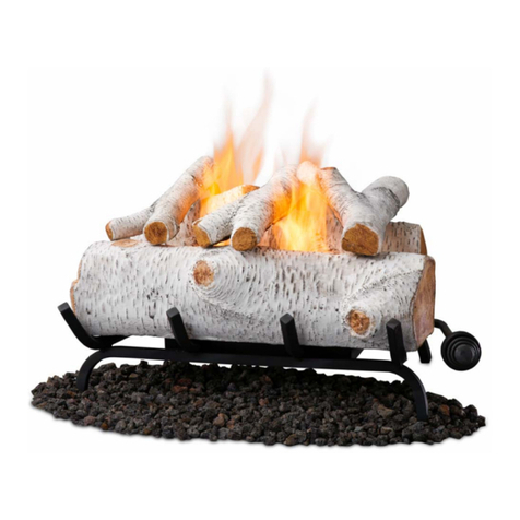
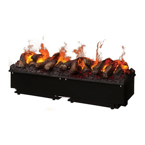
Assembling the LED Log Fuelbed
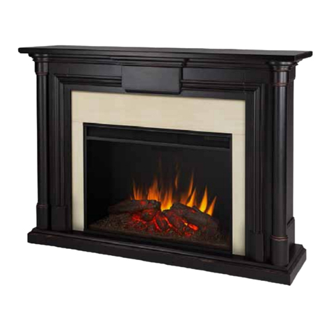
This product is equipped with a ‘metal fuelbed’. Before assembling the LED Log Fuelbed you have to lift off this metal
fuelbed and place aside, (Fig.2). You can keep this for future use. Gently lift the LED Log Fuelbed out of its packaging.
&$87,217KHIXHOEHGZHLJKVNJ%HVXUHWRRQO\OLIWWKH)XHOEHGE\WKHWZRFHQWHUORJV)LJ7KHVHDUH
WKHVWURQJHVW Place the Fuelbed on top of the appliance, there are 4 plastic guides under the Fuelbed to help locate
it, (Fig.6). The Fuelbed can be placed front to back or back to front, it is the customers preference how this is to be
orientated. Once in place lift off the small loose log, this is held in place by magnets. Under this log there is a DC wire
MDFNDQGDKROHWKURXJKWKHIXHOEHG&RQQHFWWKLVWRWKHFRUUHVSRQGLQJ'&ZLUHMDFNRQWKHSURGXFWWKURXJKWKHKROHVLQ
the Fuelbed, (Fig.7). The product is now assembled and is ready to be switched on.
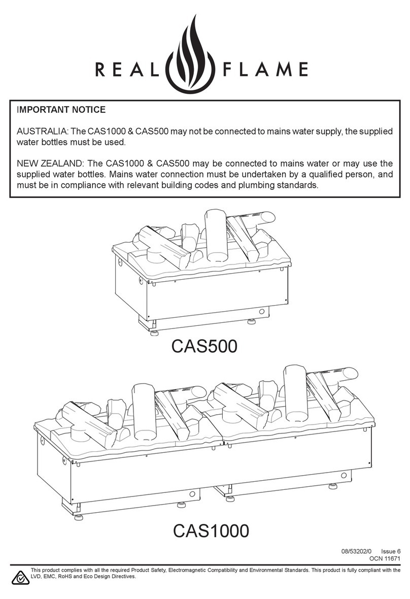
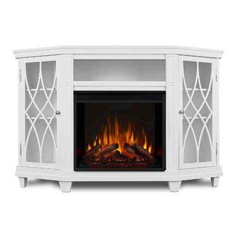
There is also a loose non LED log packed with the Fuelbed. For the CAS500 this can be placed on top of the Fuelbed
RUVWRUHGDZD\ZLWKWKHSDFNDJLQJ)RUWKH&$6WKHORRVHORJFDQEHSODFHGRQWKHFHQWHUMRLQEHWZHHQWKHWZR
Fuelbeds.
Connecting the Receiver
Take your Receiver, 4button for CAS500 and 6button for CAS1000, and with the Fuelbed removed insert the 3.5mm
MDFNLQWRWKHVRFNHWDWWKHEDFNRIWKHDSSOLDQFH)LJ,WLVYHU\LPSRUWDQWWRPDNHWKLVFRQQHFWLRQIRUWKHSURGXFW
WRIXQFWLRQFRUUHFWO\ The Receiver has a cable length of 1.4m which will allow you position it anywhere around the
product. If you prefer to hide it the Receiver can be placed inside the surround/wall. Please ensure that the Receiver is
not enclosed in metal, concrete or any other dense material, this will affect the signal from the remote control.
7KLVVHFWLRQGHVFULEHVKRZWRDFWLYDWH\RXU¿UHXVLQJHLWKHUWKHPDQXDOFRQWUROVRUUHPRWHFRQWURO
MANUAL CONTROLS
The manual controls are located beneath the Fuelbed. (Fig.9)
CAS500
0DLQV6ZLWFKµ$¶&RQWUROVWKHHOHFWULFLW\VXSSO\WRWKHDSSOLDQFH
1RWH7KLVVZLWFKPXVWEHLQWKHµ21¶I ) position for the appliance to operate
%XWWRQSDQHOµ$¶&RQWUROVWKHIXQFWLRQLQJRIWKHDSSOLDQFH
• LVWKHRQVWDQGE\EXWWRQ3UHVVLWWRWXUQRQDQGRIIWKHÀDPHHIIHFW7XUQLQJLWRQZLOOEHLQGLFDWHGE\WKHPDLQ
lights activating. Be careful not to look directly into the LED’s. These are very bright. Although the main lights operate
LPPHGLDWHO\LWZLOOWDNHDIXUWKHUVHFRQGVEHIRUHWKHÀDPHHIIHFWVWDUWV
• is the Pairing button. This will pair your remote control to the receiver. See ‘Remote Control Operation’ for details
• is the test mode button. This will be used by the manufacturer and the Service Engineer
