manuals.online logo
Brands
  1. Home
  2. •
  3. Brands
  4. •
  5. Realistic
  6. •
  7. Stereo Receiver
  8. •
  9. Realistic STA-7 User manual

Realistic STA-7 User manual

This manual suits for next models

1

Other Realistic Stereo Receiver manuals

Realistic PRO-2002 User manual

Realistic

Realistic PRO-2002 User manual

Realistic PRO-2021 User manual

Realistic

Realistic PRO-2021 User manual

Realistic STA-77L User manual

Realistic

Realistic STA-77L User manual

Realistic STA-78 User manual

Realistic

Realistic STA-78 User manual

Realistic STA-235B User manual

Realistic

Realistic STA-235B User manual

Realistic STA-21 User manual

Realistic

Realistic STA-21 User manual

Realistic STA-115 User manual

Realistic

Realistic STA-115 User manual

Realistic STA-95 User manual

Realistic

Realistic STA-95 User manual

Realistic STA-720 User manual

Realistic

Realistic STA-720 User manual

Realistic STA-95 User manual

Realistic

Realistic STA-95 User manual

Realistic STA-85 User manual

Realistic

Realistic STA-85 User manual

Realistic STA-120B User manual

Realistic

Realistic STA-120B User manual

Realistic 31-2080 User manual

Realistic

Realistic 31-2080 User manual

Realistic STA-2100D User manual

Realistic

Realistic STA-2100D User manual

Realistic STA-235 User manual

Realistic

Realistic STA-235 User manual

Realistic STA-730 User manual

Realistic

Realistic STA-730 User manual

Realistic STA-16B User manual

Realistic

Realistic STA-16B User manual

Popular Stereo Receiver manuals by other brands

Teac AG-680 Service manual

Teac

Teac AG-680 Service manual

Kenwood KR-V888D instruction manual

Kenwood

Kenwood KR-V888D instruction manual

Teac AGV1050 owner's manual

Teac

Teac AGV1050 owner's manual

Sony STR-435 operating instructions

Sony

Sony STR-435 operating instructions

Pioneer Elite SC-68 Service manual

Pioneer

Pioneer Elite SC-68 Service manual

Pioneer SX-1250 operating instructions

Pioneer

Pioneer SX-1250 operating instructions

Marantz CINEMA 70S owner's manual

Marantz

Marantz CINEMA 70S owner's manual

Kenwood KMDX92 instruction manual

Kenwood

Kenwood KMDX92 instruction manual

Yamaha RX-830 owner's manual

Yamaha

Yamaha RX-830 owner's manual

Pioneer AVH-Z7250BT owner's manual

Pioneer

Pioneer AVH-Z7250BT owner's manual

Denon AVR-1311 owner's manual

Denon

Denon AVR-1311 owner's manual

Denon AVR-S760H owner's manual

Denon

Denon AVR-S760H owner's manual

Denon AVR-X7200W Service manual

Denon

Denon AVR-X7200W Service manual

Sony XAV-1500 operating instructions

Sony

Sony XAV-1500 operating instructions

Radio Shack DX-399 owner's manual

Radio Shack

Radio Shack DX-399 owner's manual

Sony STR-DE535 - Fm Stereo/fm-am Receiver operating instructions

Sony

Sony STR-DE535 - Fm Stereo/fm-am Receiver operating instructions

Pioneer SX-1000TA operating instructions

Pioneer

Pioneer SX-1000TA operating instructions

Yamaha MusicCast TSR-5B3D owner's manual

Yamaha

Yamaha MusicCast TSR-5B3D owner's manual

manuals.online logo
manuals.online logoBrands
  • About & Mission
  • Contact us
  • Privacy Policy
  • Terms and Conditions

Copyright 2025 Manuals.Online. All Rights Reserved.

laLtstrC
lSerulce
AM /Fwt S
Catalog
STA-7
TEREO RECEIVER
Number:31 -1 968
cusroM MANUFACTURED FoR RADIo sHACK f,[n DMSIoN 0F rANDy conpoRAloN
(1)
(21
(3)
(4)
(5)
(6)
PAGE
ELECTR ICAL PERFORMANCE SPECIFICATIONS 3-4
BLOCKDIAGRAM. -....5
DISASSEMBLY INSTRUCTIONS . ., , .6-7
CIRCUIT OPERATION CHECK . . ..8_16
ALIGNMENT INSTRUCTIONS ,. . .17_20
BUILT.IN PROTECTOR CIRCUIT DESCRIPTION
(MA|N AMP tC HA-1370) . . .20
(7) TROUBLESHOOTING.. .21_23
(8) VALUE SELECTED PARTS ,,,,,..,23
(9) D|AL STRINGTNG D|AGRAM. .....24
(10) LEVEL DTAGRAM ....25
(T1) IC&TRANSISTOR LEAD IDENTIFICATION ,....25
(12) AM/FM RF rF, MPX & PRE, TONE AMP P.C.B. (TOp&BOTTOM VTEWS). .26-27
(13) MA|N AMP & POWER SUPPLY P.C.B. (TOP & BOTTOM V|EWS) .......28
(14) SPEAKER JACKS & SYSTEM/FLAT EOUALIZATION P.C.B.
(TOP & BOTTOM VIEWS) ...,..29
(15) MONTTOR SWTTCH P.C.B. (TOp V|EW) .. ........30
(16) SPEAKER SWITCH P.C.B. (TOP VIEW) . . . . .3O
(17) ELECTRTCAL PARTS L|ST 31-37
(18) EXPLODED VIEW PARTS LIST . ... 38-39
(19) rC TNTERNAL DTAGRAM (LA3350 & HA-1370) ..... .. 40-41
(20) SCHEMATTC DTAGRAM . . 42-43
(21) EXPLODED VIEW 44_45
t*/'
I
v"-
I
,I
I
I'l
-2-
1 . ELECTRICAL PERFORMANCE SPECIFICATIONS
AM BAND
Frequency Coverage
IF
Antenna Sensitivity for S/N 20 dB at 600 kHz
at 1000 kHz
at 1400 kHz
Terminal Sensitivity (20 dB S/N)
ACA at S/N 6 dB Sensitivity at 1000 kHz
S/N Ratio at 5 mV lnput
AGC Distortion at 1000 kHz,100 mV/m lnput,80 % mod.
AGC Figure-of-Merit
lF Rejection at 600 kHz
lmage Rejection at 1400 kHz
Distortion at 5 mV/m, 30 % mod.
Tape Out Level 5 mV/m lnput, 3A% 4OOHz
Fidelity 5 mV/m lnput, -O dB down (1 kHz = 0 dB)
Whistle Modulation of 2nd and 3rd Harmonic
at 1000 pYlm and 5000 pVlm
Calibration at 600 kHz
at 1000 kHz
FM BAND
Frequency Coverage
IF
IHF Sensitivity at 90,98 and 106 MHz
FM S/N Ratio at 98 MHz, 1 mV lnput
FM Limiting Sensitivity (-3 dB)
lF Rejection Ratio at 90 MHz
lmage Rejection Ratio at 106 MHz
Capture Ratio at 90 MHz, 1 mV lnput
ACA -+. 400 kHz, 100 pV lnput
Audio THD 400 H2,75 kHz dev.
Calibration Accuracy at 90 MHz
at 106 MHz
AFC Holding Range with 1 mV lnput
AM Suppression, AM - 30%, FM - 10O%
Maximum Signal Handling Capacity
Tape Out Level, 75 kHz dev. 1 mV lnput
All sets must meet the requirements of FCC.
Frequency response must meet the 75 psec de-emphasis
(50 psec de-emphasis for Australian models).
FM MPX SECTION
Stereo I ndicator Sensitivity
Separation at 1 mV lnput at 100 Hz
at 1 kHz
at 10 kHz
Stereo Distortion at 1 mV 1 kHz
38 kHz Rejection
SCA Rejection
Stereo Output Level
(UL, C.S.A.)
UNIT
(pV)
(dB)
(dB)
(dB)
%t
(dB)
(dB)
(mV)
UNIT
(kHz)
(kHz)
fuV/m)
(pVlm)
(pVlm)
(pv)
(dB )
(dB)
('/"1
(dB)
(dB)
(dB)
%t
(mV)
(Hz)
%t
(kHz)
(kHz)
UNIT
(MHz)
(MHz)
(pV)
(dBf)
(dB)
(pv)
(dB)
(dB)
(dB )
(dB)
e/,1
(kHz)
(kHz)
(kHz)
(dB )
(mV)
(mV)
NOMINAL
510-1650
455
200
200
200
10
28
40
4
45
.32 45
1.5
210
20-3000
NOMINAL
86.5- 108.5
10.7
2.8
14.2
60
3.2
BO
50
3
45
0.5
r250
3B
200
630
L!MIT
520-1620
500
500
500
20
34
10
38
27
35
3.5
210 L 2.5 dB
50-2500
15
r_25
i.50
LIMIT
88- 1 08
5.0
19.2
55
7.1
70
45
6
30
1.0
r 500
r 500
r.330
30
100
630 r 2.5 dB
LIMIT
20
22
27
2A
2.O
48
560 r 2.5 dB
8
NOMINAL
10
29
34
26
0.6
55
80
560
-3-
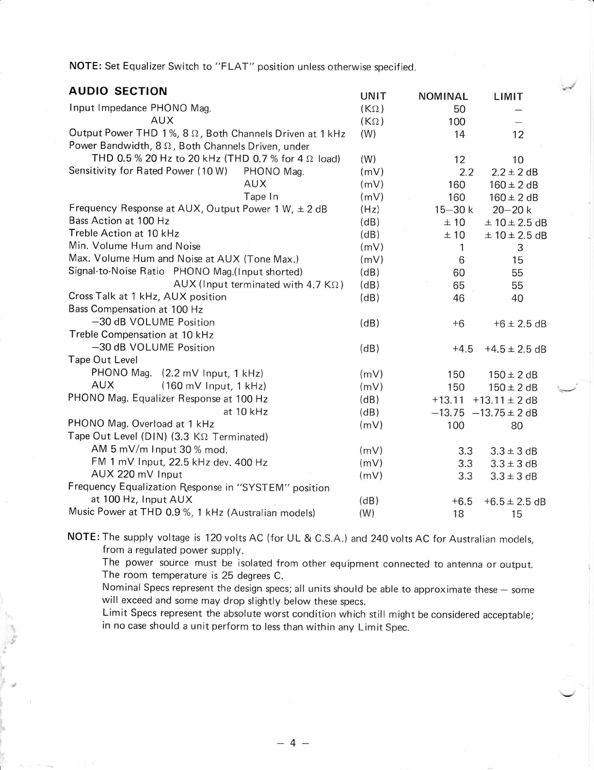
NOTE: Set Equalizer Switch to "FLAT" position unless otherwise specified.
AUDIO SECTION
lnput lmpedance PHONO Mag.
AUX
Output Power THD 1 o/o,8{1, Both Channels Driven at 1 kHz
Power Bandwidth, 8 O, Both Channels Driven, under
THD 0.5 %20Hz to 20 kHz (THD 0.7 o/ofor 4 a load)
Sensitivity for Rated Power (10W) PHONO Mag.
AUX
Tape ln
Frequency Response at AUX, Output Power 1 W, 4.2 dB
Bass Action at 100 Hz
Treble Action at 10 kHz
Min. Volume Hum and Noise
Max. Volume Hum and Noise at AUX (Tone Max.)
Signal-to-Noise Ratio PHONO Mag.(lnput shorted)
AUX (lnput terminated with 4.7 KAI
Cross Talk at 1 kHz, AUX position
Bass Compensation at 100 Hz
-30 dB VOLUME Position
Treble Compensation at 10 kHz
-30 dB VOLUME Position
Tape Out Level
PHONO Mag. {2.2mV tnput, 1 kHz)
AUX (160 mV lnput, 1 kHz)
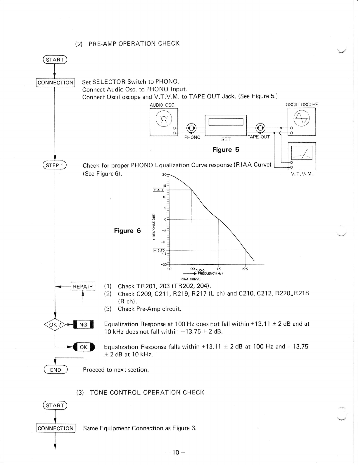
PHONO Mag. Equalizer Response at 100 Hz
at 10 kHz
PHONO Mag. Overload at 1 kHz
Tape Out Level (DlN) (3.3 KO Terminated)
AM 5 mV/m lnput 30 % mod.
FM 1 mV lnput, 22.5k1z dev. 400 Hz
AUX22O mV lnput
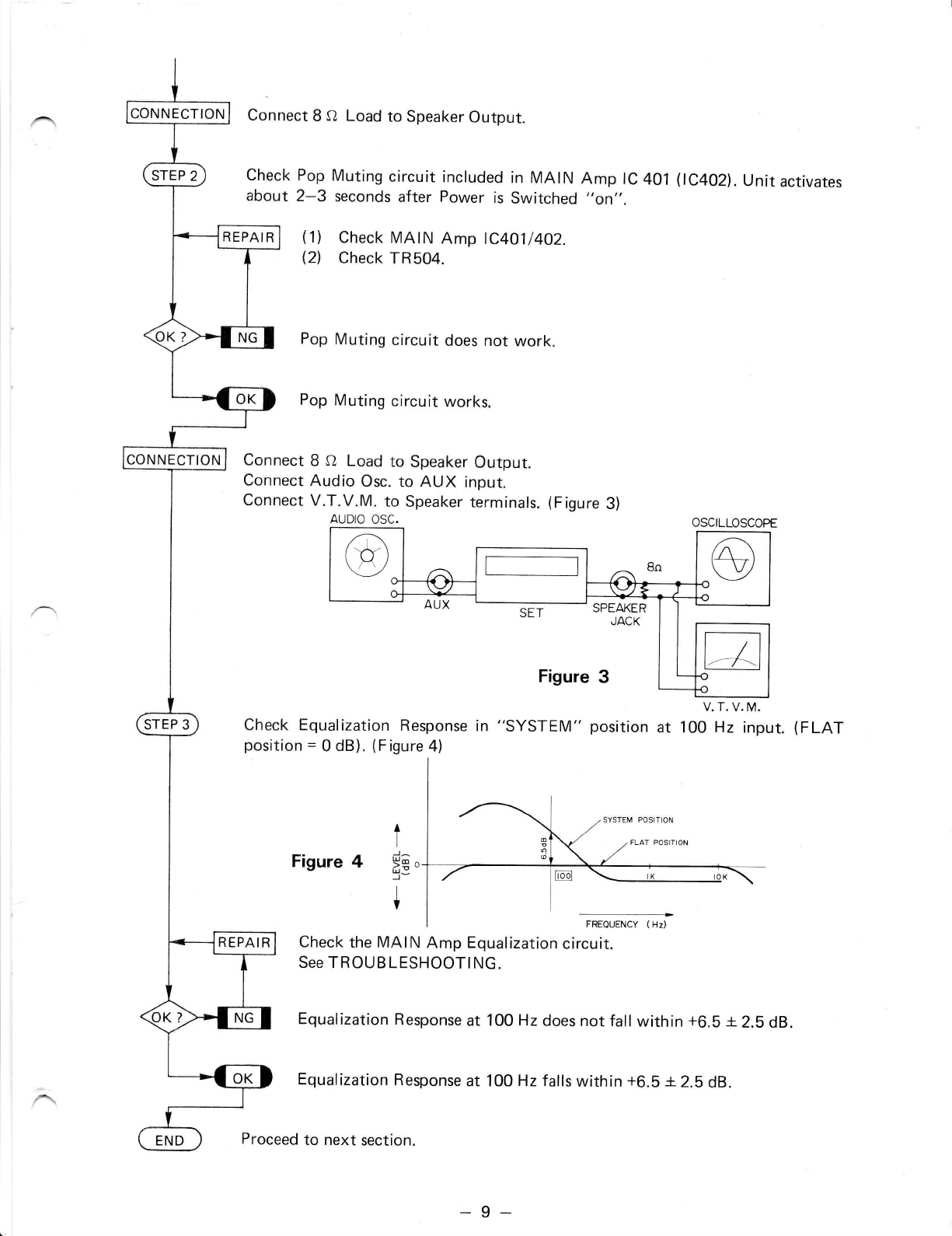
Frequency Equalization flesponse in "SYSTEM" position
at 100 Hz, lnput AUX
Music Power at THD 0.9 Yo, 1 kHz (Australian models)
,d
UNIT
(Ko )
(Ksl)
(w)
(w)
(mV)
(mV)
(mV)
(Hz)
(dB)
(dB)
(mV)
(mV)
(dB)
(dB)
(dB)
(dB)
(dB)
(mV)
(mV)
(dB)
(dB)
(mV)
(mV)
(mV)
(mV)
(dB)
(w)
NOMINAL
50
100
14
12
2.2
160
160
15-30 k
*.10
a.10
1
6
60
65
46
+6
LIMIT
12
10
2.2 r.2 dB
160i2dB
160r 2 dB
20-20 k
* 10 +. 2.5 dB
n 10r.2.5 dB
3
15
55
55
40
+6 n 2.5 dB
+4.5 +4.5 +.2.5 dB
150 150a.2 dB
150 150r.2 dB
+13.11 +13.11*.2d8
-13.75 -',13.75 r-2 dB
100 80
3.3 3.3 *.3 dB
3.3 3.3 +. 3 dB
3.3 3.3 a.3 dB
+6.5 +6.5 +. 2.5 dB
18 15
NOTE:The supply voltage is l20voltsAC (for UL & C.S.A.) and24OvoltsAC forAustralian models,
from a regulated power supply.
The power source must be isolated from other equipment connected to antenna or output.
The room temperature is 25 degrees C.
Nominal Specs represent the design specs; all units should be able to approximate these - some
will exceed and some may drop slightly below these specs.
Limit Specs represent the absolute worst condition which still might be considered acceptable;
in no case should a unit perform to less than within any Limit spec.
*4-
2. BLOCK DIAGRAM
--lI
rtl
)
U
z
z
r
G
t
I
d
J
o
U
E
F
t
U
z
f
F
r
=
c<
a6
ffo
o
o
N
G
F
Jl
UI
zl
z)
<l
II
ol
rl
Jl
bl
zl
21
<t
II
ol
-rl
t_
I
-l
o-l !
>t :
<l .
ula
(EI '
IL
Y
ti
J
z
z
-
G
o
F_l
JI
ul
zl
zl
<l Fr
rl rl
ol cl
L z-l
I
Ltr
o
F
a=o
(,)
z5
o -o
f:EE
rl
z
z
U
F
>z
t@
xo
=B
=1 =
N@-
a<F
3E;
uc-' 3?s
o66
otrE
oB'
+@
siE-
=<B
:g E- o
i!*o
=F
x
E-a
EO
=6
=8
;E
-5-
n
Writlur ttltr!rr!!
|"ffi ffi,
illilillr rilr$t'ri
l
l;
1
i
l
l-
I
I
I
3. DISASSEMBLY INSTRUCTIONS
Figure A
1)To remove chassis from MetalCabinet
a) Turn the Cabinet upside down and re-
move the six screws from the Cabinet
bottom. (Figure A)
b) Remove the five screws from the Rear
Panel. (Figure B)
Figure C1
2) Removal of Front Panel
a) Remove the chassis from Metal Cabinet
as described in 1).
b) Pull off the Metal Cabinet.
c) Remove two screws each from the top
and bottom of the Front Panel.
(Figure C1, Czl
d) Remove the two screws from the back of
Front Panel. (Figure D)
e) Remove Knobs and pull off Panel.
Figure B
Flgure C2
-6*
Figure D
3)To remove two bottom covers
i) Removal of Bottom Cover []
Remove the six (A) screws from bottom
cover @ as shown in Figure E.
ii) Removal of Bottom Cover E]
Remove the six (B) screws from bottom
cover @ as shown in Figure E.
IA
(A)
',[,'l'
1'*
B
+(B),l
a
r
*t*
*'r*'"-
(B) ,<--(A)
Figure E
4)To remove Rear Panel from chassis
a) Remove bottom covers as described in 3).
b) Remove the two screws from bottom of
Rear Panel. (Figure F)
c) Remove the four screws frorn the Rear
Panel. (Figure G)
Figure F
Figure G
-7 -
START
CONNECTION
4. CIRCUIT OPERATION CHECK
1)POWER SUPPLY OPERATION CHECK
Connect AC Cord to 120 V AC, 60 Hz (UL, C.S.A.l (24O V AC, 50 Hz for Australian)
Check the Power Supply voltages. (Figure 1)
Check the Power Supply circuits, Fuse and Power Transformer.
DC voltages are not correct.
DC voltages are correct.
Proceed to next section.
2)AUDIO SECTION OPERATION CHECK
(1) MAIN AMP. OPERATION CHECK
Connect 8 O Load to Speaker Output.
Connect DC Voltmeters to Pin No. 3 of MAIN lC 401 (lC4O2) and ground (Plus
Supply) and Pin No. 10 and ground (Minus Supply). See Figure 2.
MAIN AMP EOARD DC VOLTMETER
Figure 2
Check Power Supply Voltage with No lnput (must be r21.2V).
Check D501-504, C505, 506.
Check for short-circuits.
DC Voltage is not i 21.2 V .
DC Voltage is r21.2Y.
9.7V
ltto a 6
CONNECTION
REPAI R
-8-
CONNECTION
NECTION
REPAIR
Connect 8 o Load to Speaker Output.
Check Pop Muting circuit included in MAIN Amp lC 401
about 2-3 seconds after Power is Switched "an,,. (lC4O2l. U nit activates
(1) Check MAIN Amp lC4O1l4O2.
(21 Check TR504.
Pop Muting circuit does not work,
Pop Muting circuit works.
Connect 8 O Load to Speaker Output.
Connect Audio Osc. to AUX input.
Connect V.T.V.M. to Speaker terminals. (Figure 3)
AUDIO OSC.
Check Equalization Response in "SYSTEM" position
position = 0 dB). (Figure 4)
V. T. V. M.
at 100 Hz input. (FLAT
Figure 4t
;e"
+
Check the MAIN Amp Equalization circuit.
See TROUBLESHOOTING.
Equalization Response at 100 Hz does not fall within +6.5 i 2.5 dB.
Equalization Response at 100 Hz falls within +6.5 -+.2.5 dB.
to next section.
Proceed
-9-
CONNECTION
REPAIR
QI PRE.AMP OPERATION CHECK
Set SELECTOR Switch to PHONO.
Connect Audio Osc. to PHONO lnPut.
connect oscilloscope and V'T.V.M' to TAPE oUT Jack' (see Figure 5')
AUDIO OSC. OSCILLOSCOPE
SET
Figure 5
Equalization Curve response (RIAA Curve)
Check for proper PHONO
(See Figure 6).
I+13.r'l
Figure 6
20 -3pHgor.""r,*,
(1) check rR2o1, 2m (rJ;Lf irol.
(21 Check C209,C211,R219,R217 (L ch) and C210,C212,R22O^R218
(R ch).
(3) Check Pre-Amp circuit.
Equalization Response at 100 Hz does not fall within +13.11 r-2 dB and at
'10 kHz does not fall within -13.75 -+.2 dB.
Equalization Response falls within +13.11 L2dB at 100 Hz and -13.75
+.2 dB at 10 kHz.
Proceed to next section.
(3) TONE CONTROL OPERATION CHECK
Same Equipment Connection as Figure 3.
a
36
U
6
U
E
t -,o
I
l- r3.751
-15
t5
to
o
-to
- 10-