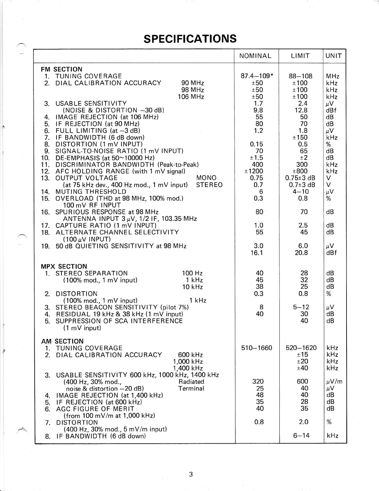
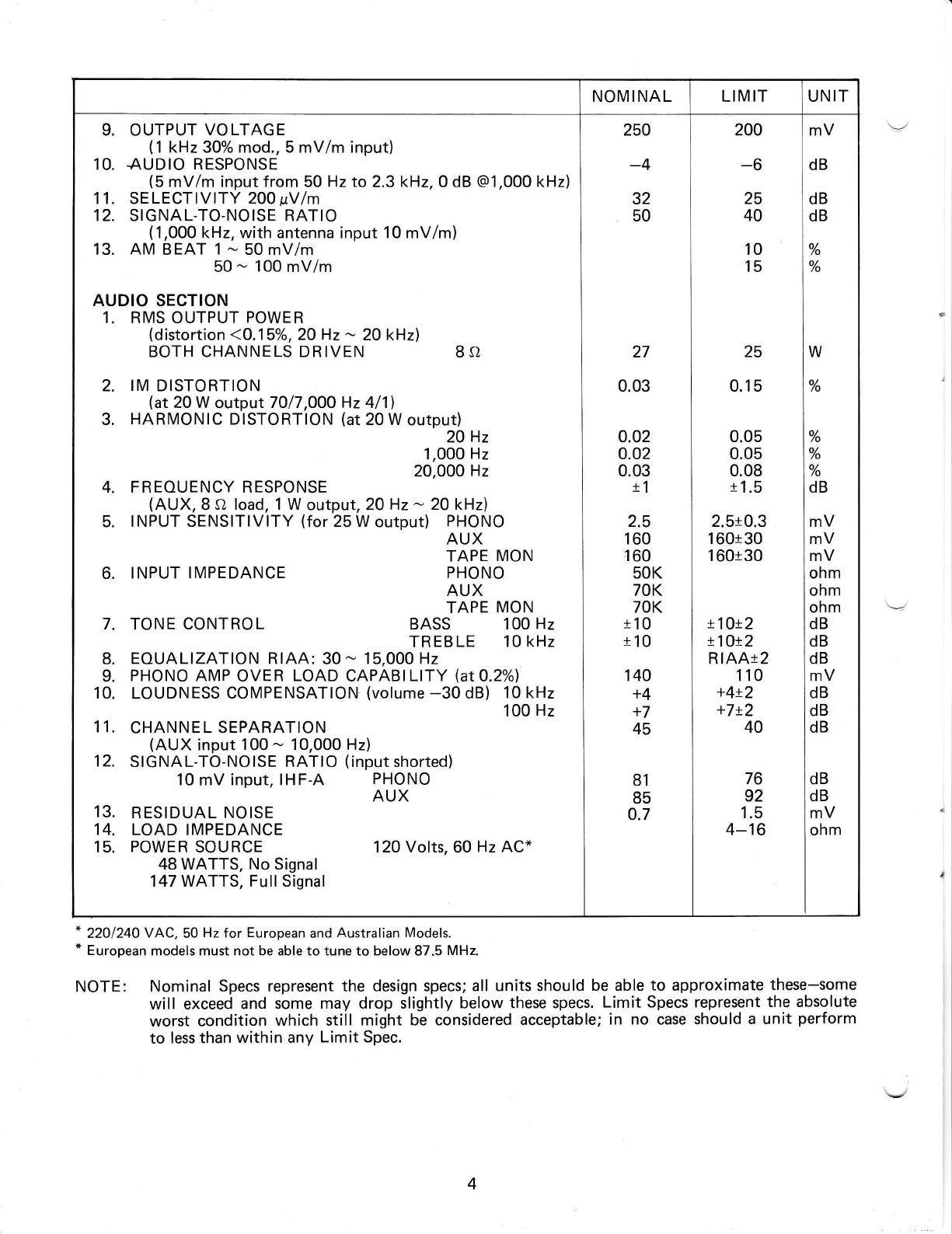
Realistic STA-720 User manual

ruLtstd.
Serulce amuaI
AM/FM STA-720
STEREO REGEIVER
Catalog Number: 31-1997
L'
{D
cusloM MANUFACTURED FoR RADIo sHACK[n ovstoN 0F TANDv coRpoRATtoN

CONTENTS
1. SPECIFICATIONS .3&4
2, BLOCK DIAGRAM. ......5
3. DISASSEMBLYINSTRUCTIONS. .........6
4. DIAL STRINGING DIAGRAM .........6
5. ALIGNMENT PROCEDURES .7 _9
6. ALIGNMENT POINTS.. .. ....10
7. LEVELDIAGRAM. .......11
8. TROUBLESHOOTING... 12_16
9. 0074 TUNER BOARD. . . 17 & 18
10. 6079 MAIN AMP BOARD 19 & 20
11. 7225 FREOUENCY COUNTER BOARD ., , . ,,. ,.21 L/
12. 7226 SWTTCH BOARD .....22
13. 8044 POWER SUPPLY BOARD , ,. , ,., .23
24
14. 9046 TONE CONTROL BOARD . ! ! r... ! !/
15. SEMICONDUCTOR LEAD IDENTIFICATIONS .... ..,.,..25
16. ELECTRTCAL PARTS LIST .... 26- 33
17. lC EOUIVALENT CIRCUIT ........34
18. MTSCELLANEOUSPARTSLTST. ......35
19. SCHEMATIC DIAGRAM. . SEPARATE SHEET
I
l
I
I
\
20, EXPLODED VIEW. . SEPARATE SHEET :
+
'e

SPECIFICATIONS
NOMI NAL LIMIT UN IT
FM
1.
2.
SECTION
TUNING COVERAGE
DIAL CALIBRATION ACCURACY 90 MHz
98 MHz
106 MHz
USABLE SENSITIVITY
(NOTSE & DTSTORTTON -30 dB)
IMAGE REJECTION (at 106 MHz)
lF REJECTION (at 90 MHz)
FULL LIMITING (at -3 dB)
lF BANDWIDTH (6 dB down)
DISTORTION (1 mV INPUT)
SIGNAL-TO-NOISE RATIO (1 mV INPUT)
DE-EMPHASIS (at 50-10000 Hz)
DISCRIMINATOR BANDWIDTH (Peak-to-Peak)
AFC HOLDING RANGE (witfr 1 mV signal)
OUTPUT VOLTAGE MONO
(at 75 kHz dev., 4OOHz mod., 1 mV input) STEREO
MUTING THRESHOLD
OVERLOAD (THD at 98 MHz, 100% mod.)
100 mV RF INPUT
SPURIOUS RESPONSE at 98 MHz
ANTENNA INPUT 3 pV, 112lF, 103.35 MHz
CAPTURE RATIO (1 mV INPUT)
ALTE RNATE CHANNE L SE LECTIVITY
(100 pV INPUT)
50 dB OUIETING SENSITIVITY at 98 MHz
3.
4.
5.
6.
7.
8.
9.
10.
11.
12.
13.
14.
15.
16.
17.
18.
19.
Radiated
Terminal
MPX SECTION
1, STEREO SEPARATION
(100% mod., 1 mV input) 100 Hz
1 kHz
10 kHz
2, DISTORTION
(1OOY" mod., 1 mV input) 1 kHz
3. STEREO BEACON SENSITIVITY (pilot 7%)
4. RESIDUAL 19 kHz & 38 kHz (1 mV input)
5. SUPPRESSION OF SCA INTERFERENCE
(1 mV input)
AM SECTION
1. TUNING COVERAGE
2. DIAL CALIBRATION ACCURACY 600 kHz
1,000 kHz
1,400 kHz
3. USABLE SENSITIVITY
(400 H2,30% mod., 600 kH2,1000 kHz, 1400 kHz
noise & distortion -20 dB)
4. IMAGE REJECTION (at 1,400 kHz)
5. lF REJECTION (at 600 kHz)
6. AGC FIGURE OF MERIT
(from 100 mV/m at 1,000 kHz)
7. DISTORTION
(400 H2,30% mod., 5 mV/m input)
8. lF BANDWIDTH (6 dB down)
87.4-109*
tb0
t50
t50
1.7
9.8
55
80
1.2
0.15
70
t 1.5
400
t12OO
0.75
o.7
6
0.3
80
1.0
55
3.0
16.1
40
45
38
0.3
8
40
510-1660
320
25
48
35
40
0.8
BB_1OB
t 100
t 100
t 100
2.4
12.8
50
70
1.8
t 150
0.5
65
t2
300
tB00
0.75t3 dB
0.7t3 dB
4-10
0.8
70
2.5
45
28
32
25
0.8
6.0
20.8
5-12
30
40
520-1620
t15
t20
t40
2.0
6-14
600
40
40
28
35
MHz
kHz
kHz
kHz
pV
dBf
dB
dB
pV
kHz
o/
/o
dB
dB
kHz
kHz
V
pV
o/
/o
dB
dB
dB
dB
o/
/o
kHz
kHz
kHz
kHz
pY lm
pV
dB
dB
dB
o/
/o
kHz
dB
dB
pV
dBf
pV
dB
dB
-.,\

NOMINAL LIMIT UN IT
9. OUTPUT VOLTAGE
(1 kHz 30% mod., 5 mV/m input)
10. AUDIO RESPONSE
(5 mV/m input from 50 Hz to 2.3 kHz, 0 dB @1,000 kHz)
11. SELECTIVITY 200 pVlm
12, SIGNAL-TO-NOISE RATIO
(1,000 kl-{2, with antenna input 10 mV/m)
13. AM BEAT 1 - 50 mV/m
50 - 100 mV/m
AUDIO SECTION
1. RMS OUTPUT POWER
(distortion <O.15%, 20 Hz - 20 kHzl
BOTH CHANNELS DRIVEN 8 O
2. IM DISTORTION
lat2O W output 7O/7,OOO Hz 411\
3. HARMONIC DISTORTION (at20 W output)
20 Hz
1,000 Hz
20,000 Hz
4, FREOUENCY RESPONSE
(AUX, 8 o load, 1 W output, 20 Hz - 20 kHzl
5. INPUT SENSITIVITY (for 25 W output) PHONO
AUX
TAPE MON
PHONO
AUX
TAPE MON
BASS 100 Hz
TREBLE 10 kHz
8. EOUALIZATION RIAA: 30 - 15,000 Hz
9. PHONO AMP OVER LOAD CAPABILITY (atO.2o/ol
10. LOUDNESS COMPENSATION (volume -30 dB) 10 kHz
100 Hz
11. CHANNEL SEPARATION
(AUX input 100 - 10,000 Hz)
12. SIGNAL-TO-NOISE RATIO (input shorted)
10 mV input, IHF-A PHONO
AUX
13. RESIDUAL NOISE
14. LOAD IMPEDANCE
15. POWER SOURCE
48 WATTS, No Signal
147 WATTS, Full Signal
120 Volts, 60 Hz AC*
6. INPUT IMPEDANCE
7. TONE CONTROL
250
-4
32
50
27
0.03
0.02
o.o2
0.03
t1
2.5
160
160
50K
70K
70K
t10
t10
140
+4
+7
45
81
85
o.7
200
-6
25
40
10
15
25
0.15
0.05
0.05
0.08
t1.S
2.5t0.3
1 60t30
1 60t30
t1Ox2
r1Or2
RIAAt2
110
+4x2
+7t2
40
76
92
1.5
4-16
mV
dB
dB
dB
o/
/o
o/
/o
o/
/o
o/
/o
o/
/o
o/
/o
dB
W
mV
mV
mV
ohm
ohm
ohm
dB
dB
dB
mV
dB
dB
dB
dB
dB
mV
ohm
* 2201240 VAC, 50 Hz for European and Australian Models.
* European models must not be able to tune to below 87.5 MHz.
NOTE: Nominal Specs represent the design specs; all units should be able to approximate these-some
will exceed and some may drop slightly below these specs. Limit Specs represent the absolute
worst condition which still might be considered acceptable; in no case should a unit perform
to less than within any Limit Spec.

BLOCK DIAGRAM
l " =..l..'.E l
I e :;E**1 i
! z- FS.E
i ;!qui;r;l I
sut)vlas
1
+
EI
_1
t'-t
aad
E
e=q
I i== ;
: ;>?o.
y o<F=J
r
1___--i
ttt. l
-t t=t!l
E 6:6 Ed Hd
]]NNVH! TB!IU
5
<E
trF
a
A

DISASSEMBLY INSTRUCTIONS
1. Removing chassis from metal enclosure.
Remove five screws (#63 & #41lr from sides and back.
2. Removing the Front Panel
Pull off all of the control knobs except for push buttons.
Remove six screws (#35) from top and bottom of the Front Panel,then remove the Front Panel.
(Refer to Miscellaneous Parts List for descriptions of numbered parts.)
DIAL STRINGING DIAGRAM
Note: Tuning capacitor should be in fully closed position.
fi-rl2 TURNS)
6

ALIGNMENT PROCEDURES
Do not attempt alignment unless the following equipment is available.
1. AM Signal Generator
2. Oscilloscope
3. AC Voltmeter
4. FM Signal Generator
5. Stereo Modulator
6. Audio Generator
7. Distortion meter
8. DC Voltmeter
9. Frequency Counter
when aligning.
Note: Remove line cord antenna from FM external antenna terminal
AM IF & RFALIGNMENT
Note: Remove line cord antenna from FM external antenna terminal when aligning.
RECEIVER
Loop Antenna
Fis. 1 AM ALIGNMENT CONNECTION
TAPE OUT
Output of signal generator should be no higher than necessary to obtain an output reading.
Signal Generator Modulation: 30%
Set SELECTOR switch to AM.
STEP SIGNAL
GENERATOR
COUPLING
SIGNAL
GENERATOR
FR EOUENCY
RECEIVER
DIAL
SETTING INDICATOR ADJUSTMENT
Refer Fig. 4. REMARKS
1Refer Fig. 1455 kHz
(400 Hz Mod.)
Point of non-
interference
(on/about
600 kHz)
AC Voltmeter
to TAPE OUT
jack 1401 ilFT) Adjust for maxi-
mum reading.
2Same as Step 1600 kHz
(400 Hz Mod.) 600 kHz Same as Step 1L401 (OSC Coil)
L451 (ANT Coil) Same as Step 1
3 Same as Step 11400 kHz
(400 Hz Mod.) 1400 kHz Same as Step 1
TC402
(OSC Trimmer)
TC4O1
(ANT Trimmer) Same as Step 1
TUNER
FRONT END
TC401,TC402
L401

FM RF AND IF ALIGNMENT
For European model, the lowest frequency of FM tuning range should not be below 87.5 MHz.
FM Dummy Antenna to 300 S2 antenna terminal of Receiver
Zin = 50 o (75 o) Zout=3OOO (balanced)
Signal generator output should be no higher than necessary to obtain an output reading.
Set Selector switch to FM.
Signal Generator deviation: 75kH'z NOTE: Be sure to disconnect FM line cord antenna during alignment.
STEP SIGNAL
GENERATOB
COUPLI NG
SIGNAL
GENERATOR
FR EOUENCY
R ECE IVER
DIAL
SETTI NG INDICATOR ADJUSTMENT
Refer Fig. 4. R EMARKS
'|
Connect to FM
Antenna Termi-
nal thrbugh
FM Dummy
Antenna
(300 O) Fis. 2
90 MHz
(400 Hz Mod.) 90 MHz AC Voltmeter
connected to
TAPE OUT
jack
L1 01
(ANT. COIL)
L102
(RF COIL)
L1 04
(OSC. COIL)
Adjust for maxi-
mum reading on
AC Voltmeter.
2Same as Step 1106 MHz
(400 Hz Mod.) 106 MHz Same as Step 1
TClO1
(ANT. Trimmer)
TC1 02
(RF Trimmer)
TC103
(OSC. Trimmer)
Same as Step 1
Repeat steps 1 & 2 until no further improvement is possible.
3Same as Step 190 MHz
(400 Hz Mod.) 90 MHz Same as Step 1T101 flFT) Same as Step 1
4Same as Step 198 MHz
(400 Hz Mod.) 98 MHz DC Voltmeter
connected to Pin
#31 and TP on
PCB #OO74A
T201 Adjust tor zero
reading on DC
Voltmeter.
5Same as Step 198 MHz
(400 Hz Mod.) 98 MHz Distortion Meter
connected to
TAPE OUT
jack T202 Adjust for mini-
mum distortion.
6Same as Step I98 MHz
(400 Hz Mod.) 98 MHz SIGNAL
STRENGTH
lndicator LED VR201 Adjust for Full
Signal lndication
with input of
500 pV
7
Same as Step 1
(Set Selector
switch to FM
MUTE.)
98 MHz
(400 Hz Mod.) 98 MHz Same as Step 1vR202
Adjust for zero
reading on AC
Voltmeter with
SG output level
of 6 ptV
12s a (112.5 s,)
150 r, Fig,2 FM DUMMY ANTENNA

MPX ALIGNMENT
FM ANTENNA
TERMINAL
(300 a)
MAIN AMPLIFIER ALIGNMENT
TAPE OUT
Pin #46
TUNER
FRONT END
L101, L102
, Ll04
T201 , TC1 01
TC102. TC103
FM SIGNAL
GENE RATOR FM DUMMY
ANTENNA
300 C,
FM IF
VR201
vR202
MPX
VR3O1
VR3O2
STE BEO
MODULATOR
Fis.3 FM RF, lF AND MPX ALIGNMENT CONNECTION
Set SELECTOR Switch to FM.
Tune for 98 MHz on band.
Signal Generator output level: 1000pV Deviation: 75 kHz at 100% modulation of composite signal
Connect Sigpal Generator to FM Antenna Terminal through FM Dummy Antenna (300 S)).
STEP
19 kHz
(PILOT SIGNAL)
MODULATION
Level
SIGNAL
GENERATOR
Freq. Set to
OUTPUT
INDICATOR
Connected to
ADJUST
Refer
Fig. 4
ADJUST
FOR NOTE
Frequency counter
connected to Pin
#46 and Ground VR301 19 kHz
28o/" Composite 1 kHz
R channel
AC Voltmeter
connected to
TAPE OUT jack
of R channel
Adjust input
for Audio out-
put of about
0.7 v.
38o/o Composite 1 kHz
L channel
AC Voltmeter
connected to
TAPE OUT jack
of R channel
VR3O2 minimum
AC Voltmeter
reading should
be at least 32
dB below read-
ing in step 2.
48o/o Composite i kHz
R channel
AC Voltmeter
connected to
TAPE OUT jack
of L channel
VR302 mrntmum same as Step 3
lf you did not obtain -32 dB readings in steps 3 and 4 (compared with step 2), readjust VR302 until you obtain -32 dB
reading for both steps 3 and 4.
INDICATOR ADJUSTMENT REMARKS
DC Voltmeter V R601a,b Adjust for 0.005 - 0.015 volts
across R619 a, b with no signal.

ALIGNMENT POINTS
VR601a R619a #3lPrN L45l Tl 01
Ll 04
102
Lt0l
TCl 03
TCl02
TCI(]1
TC40t
TC402
T401
1401
vR202
TP
VR20l
r201
T202
V R3O2
#46 PtN
VR3(]1
$ls &:,* -wail
Fis.4
vR60lb R619b
10

LEVEL DIAGRAM
FREOUENCY - lkHz
SPEAK E R
OUT
m
!60
.g
z
a50
o
LrJ
Oii
F
o
VO LUME
I NPUT
SELECTO 8
l4.l4v
25W /8s2
11

TROUBLESHOOTING
SYMPTOM CAUSE AND REMEDY
Receiver not operative; function
indicator des not light. A) Faulty AC power cord
Replace the cord.
B) Defect in the power switch
Replace the switch.
C) Broken wire in the power transformer
R ep lace the transformer.
D) Blown power fuse F002
Replace the fuse.
2. Fr.rse blows when power is turned on. A) Power transformer T851 defective
Replace the transformer.
B) Short in the primary or secondary of the transformer
circuitry
Repair the short.
C) Damaged rectifier D801
Replace the rectifier.
D) Short circuit in the rectif ier circuit
Repair the short.
3. Function indicator lights but no
sound from both channels. A) SPEAKERS switch 510 or 511 defective
Replace the defective switch(es).
B) Defebt in transistors TR605a,b - TR60Ba,b of
Main Amp Board #6079
Replace the defective transistor(s).
4. A speakers do not work. A) Speaker switch S10 defective
Replace the switch.
5. B speakers do not work. A) Speaker switch S11 defective
Replace the switch.
6. One channel does not work with
VOLUME at maximum with a test
signal applied to the center terminal
of VOLUME control VR902 of the
dead channel.
A) Defective 1C901
Replace 1C901 .
B) Defect in transistbr TR601-TR610 of Main Amp
Board #6079
Locate and correct the defect.
C) Break in copper foil of printed circuit board
#9046 or #6079
Repair or replace circuit board(s).
D) Short in speaker output terminal
Repair the short.
E) Defective resistor R901, R601, R603-R610,
R615-R620
Replace the defective resistor(s).
F) Defective capacitor C901, C601, C603 or C604
Replace the defective capacitor(s).
12

SYMPTOM CAUSE AND REMEDY
7. Same as (6) above but channel
operates when test signal is applied
as in (6).
A) Defective PHONO switch 52 or TAPE MON switch
S7
Repair or replace the switch(es).
B) Defective BALANCE control VR901
Replace.
C) Resistor R910 defective
Replace the resistor.
B. Speaker works normally but
headphone do not work. A) Headphone plug does not mate with jack.
Replace the plug.
B) Defective resistor R651a,b
Replace the resistor(s).
9. All inputs work normally except
for AUX input. A) Poor contact in AUX input jack
Repair or replace the jack.
B) Faulty AUX switch S1
Repair or replace the switch.
C) Defective resistor R510
Replace the resistor.
10. PHONO input not operative A) Defective 1C501
Replace the lC.
B) Faulty resistor R501, R503-R509
Replace the faulty resistor(s).
C) Fau lty capacitor C501 -C503
Replace the faulty capacitor(s).
D) Poor contact in PHONO input jack
Repair or replace the jack.
E) Faulty PHONO switch 52
Repair or replace the switch.
11. TAPE MON not operative Defective TAPE MON switch 57
Repair or replace the switch.
Defective contact in TAPE lN jack(s)
Repair or replace the jack(s).
A)
B)
12. FM does not operate. A) Short circuit in Tuner B+ circuit
Repair the short.
B) Defective FM(S4) or FM MUTE(S5) switch
Repair or replace the switch(es).
C) Resistor R219, R306, R317 or R318 defective
Replace the defective resistor(s).
D) Choke coil L201 defective
Replace the coil.
E) Capacitor C302 defective
Replace the capacitor.
F) Defective lC 1C201 or 1C301
Replace the defective lC(s).
G) Defective I FT T101
Replace lFT.
13

SYMPTOM CAUSE AND REMEDY
H) DefectivetransistorTRl0l, TR102, TR103 or
coil L101, L104
Replace the defective component(s).
l) Faulty lead-in
Repair the faulty lead-in.
13. Poor multiplex separation A) lmproper adjustment
Readjust VR302 (refer to ALIGNMENT
PROCEDURE on page g).
B) Transistor TR302, TR303 or lC 1C301 of Tuner
Board #OO74 defective
Replace the defective component(s).
C) Variable resistor VR301 or VR302 defective
Replace the defective variable resistor(s).
14. Stereo indicator does not light. A) Defective indicator LED D406
Replace the LED.
B) lmproper adjustment of VR301 of Tuner Board
#0o74
Make readjustment.
(Refer to MPX ALIGNMENT on page 9.)
C) Defective lC 1C301 or resistor R426
Replace the defective component(s).
15. FM volume not sufficient A) lf volume of both L and R channels not enough:
Front-End section defective, or faulty IFT T101
lC 1C201 or transistor TR201 of Tuner Board
#0074
Locate and replace the defective component(s).
B) lf sound of one channel not enough: Defective
TR302 in case of L channel, or defective TR303
in case of R channel
Replace the defective transistor.
16. AM does not operate A) Damaged 1C401 of Tuner Board #0074
Replace the lC.
Defective L4O1,T4O1,T4O2 or CF401
Replace the defective component(s).
One of resistors of Tuner Board #0074 (AM
section) defective
Replace the defective resistor.
One of capacitors of Tuner Board #0074 (AM
section) defective
Replace the defective capacitor.
AM switch 53 defective
Repair or replace the switch.
Defective Tuning gang capacitor
Repair or replace.
Damaged AM Bar antenna
Repair or replace bar antenna.
B)
c)
D)
E)
F)
G)
14

SYMPTOM CAUSE AND REMEDY
17 . LOUDN ESS has no effect. A) Defective LOUDNESS switch 59
Replace the switch.
B) Defective capacitor C91 1, C912 or resistor R91 1
Replace the defective component(s).
C) Defective VOLUME control VR902
Replace.
18. Stereo-Mono not effective A) Defective MONO switch 58
Replace the switch.
19. TAPE MONitor not effective A) Defective TAPE MON switch 57
Replace the switch.
B) Poor contact in TAPE MON lN jacks
Repair or replace the jack(s).
20. BASS control has no effect. A)
B)
BASS control VR903 defective
Replace.
Defective capacitor C903, C904 or resistor
R915, R917
Replace the defective component(s).
21. TREBLE control has no effect. A) TREBLE control VR904 defective
Replace.
B) Defective capacitor C905-C907 or resistor
R918, R919
Replace the defective component(s).
22. Excessive noise with PHONO input A) Faulty 1C501
Replace the lC.
B) Faulty R501-R504, C501 or C506
Replace the faulty component(s).
23. Noisy VOLUME control A) Defective VOLUME control VR902
Replace the variable resitor.
B) Defective capacitor C503, C901, C908 or C601
R ep lace the defective capacitor( s).
24. SIGNAL STRENGTH indicator
LED not functioning A) Defective LED D401-D405 or lC4O2
Replace the defective component(s).
B) ln case of FM reception, VR201 or D2O2
defective
Replace the defective component(s).
C) ln case of AM reception, 1C401 or R416 defective
Replace the defective component(s).
25. AUTO-Magic AFC has no effect
when AUTO-M switch is ON. A) Defective D 101, R 1 18, R22O or C213
Replace the defective component(s).
15

SYMPTOM CAUSE AND REMEDY
26. Frequency counter LED does not
light when FM or FM MUTE button
is pressed in.
A) Diode D803 defective
Replace the diode.
B) Capacitor C701, C704, C810
Replace the defective capacitor(s).
27. Frequency counter misreads in AM
or FM reception. A) Defective crystal XR701
Replace the crystal.
B) Defective lC 1C701 or transistor TR702-TR705
Replace the defective component(s).
28. Frequency counter misreads in only
AM reception. A) Defective AM switch 53
Replace the switch.
NOTES
1. This Receiver have two built-in over load thermal protection for abnormaloperation. When the temper-
ature of thermal protector [one is installed with heat sink (S14, 105'C) and the other with power
transformer (S13, 90'C)] does rise abnormally (105 t 5"C or 90 + 5oC), the thermal protector will
automatically cut out, and as soon as the temperature goes down sufficiently (35 t t5'C), the ther.mal
protector turns back-on automatical ly.
lf the Receiver does turn itself off, check ventilation and speaker connections.
HEAT SINK Ft)R POWER
POWER TRANSISTORS TRANSFOEIVIEB
2. Transistors TR609 and TR610 protect audio output stage when abnormally high current flows in
TR607 and TR608 due to excessive input drive, or a too low impedance load connected at output.
TR609 and TR610 are not normally biased on and collectors of thesetransistors (through D603and
D604 diodes) reduce biases on TR605 and TR606. This decreases drive to output transistorsTR60T
and TR608 to reduce the current. This occurs not only to protect the circuit but also the speakers
against high level switching clicks and pop noises.
AC I2OV
60Hz
+Vcc
F
=
a
E
-
E
o
o
F
TH E R I\4AL
PROTECTO R

OOT4.TUNER BOARD (TOP VIEW}
17

OO74 TUNER BOARD (BOTTOM VIEW}
18

6079 MAIN AMP BOARD (TOP VIEW)
t---
&
f
19

6079 MAIN AMP BOARD (BOTTOM VIEW)
---J
JI
20
This manual suits for next models
1
Table of contents
Other Realistic Stereo Receiver manuals

Realistic
Realistic STA-235 User manual

Realistic
Realistic STA-115 User manual

Realistic
Realistic STA-730 User manual

Realistic
Realistic STA-120B User manual

Realistic
Realistic STA-7 User manual

Realistic
Realistic PRO-2002 User manual

Realistic
Realistic STA-77L User manual

Realistic
Realistic STA-78 User manual

Realistic
Realistic 31-2080 User manual

Realistic
Realistic STA-95 User manual